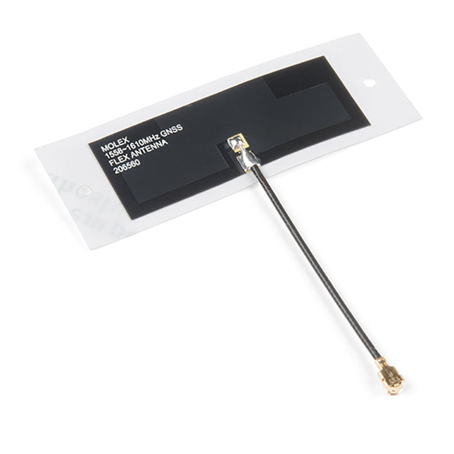
The Molex Flexible GNSS Antenna has a tiny footprint at 40.40mm x 15.40mm, while the adhesive pad is a bit bigger at 56.40mm x 20mm. Even better, the antenna is only 0.1mm thick (or about the thickness of a piece of paper). Remove the backing and stick this to any surface, or leave the backing on (be careful of the fragile U.FL connector). Features Cable length: 50mm Connector: U.FL Radiation Pattern: Omnidirectional Polarization: Linear Weigth: 0.466 g Mounting Style: Adhesive Protocol: BeiDou, Galileo, GLONASS, GPS Return Loss: < -8dB Peak Gain (Max): 1.1 dBi+ Efficiency: >74% Input Impedance 50 Ohms
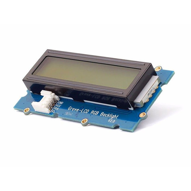
With the help of the Grove I²C connector, only 2 signal pins and 2 power pins are needed. You don't even need to care about how to connect these pins. Just plug it into the I²C interface on Seeeduino or Arduino/Raspberry Pi+baseshield via the Grove cable.
No complicated wiring, no soldering, no need to worry about burning the LCD caused by the wrong current limiting resistor. Easy peasy.
Specifications
Battery: Exclude
Input Voltage: 5 V
Dimensions: 83 x 44 x 13 mm
Weight: 42 g
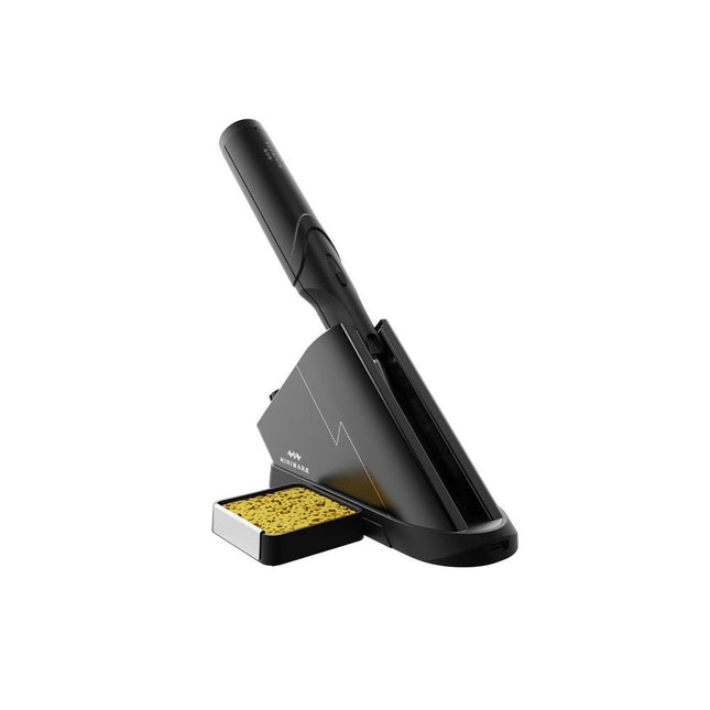
The Miniware Cordless Soldering Station TS1C (with integrated OLED screen and Bluetooth) is an intelligent soldering tool that heats up to 400°C in less than 20 seconds. Thanks to the built-in battery, the wireless soldering pen sits comfortably in the hand and is easy to use.
Features
New high-efficiency supercapacitor energy storage technology, 10,000-level charge and discharge times
Seperate design + true wireless, enjoy wireless soldering experience
BLE4.2 Bluetooth communication technology to realize remote control and setting
Standard PD2 20 V 45 W max power input, up to 36 W soldering power, can continuously solder more than 180 solder joints (0805) with a single full charge
Control station preheating to improve heating efficiency
3 expansion slots for accessories
Control Station
Standard PD2 20 V 45 W max power input, over current safety protection
128x64 pixel OLED screen, display soldering pen status in real time
Control station preheating, improve heating efficiency
Remote control and setting: temperature regulating, menu setting, viewing device info and status, etc.
Work as soldering stand and charging station
3 expansion slots for multiple expandable accessories like sponge slot
Soldering Pen
Built-in 750F high-efficiency energy storage supercapacitor, can be charged via control station (or via its USB Type-C interface in emergency cases)
36 W maximum heating power, can solder more than 180 solder joints (0805) continuously under a single full charge
Compatible with Miniware 3.5 mm audio interface soldering tips (TS80/80P soldering tip series)
Boost mode (holding the button on the pen)
Included
TS1C Soldering pen
TS1C Control station
Soldering tip (TS-B02)
Silicone cable
Sponge slot incl. sponge
Manual
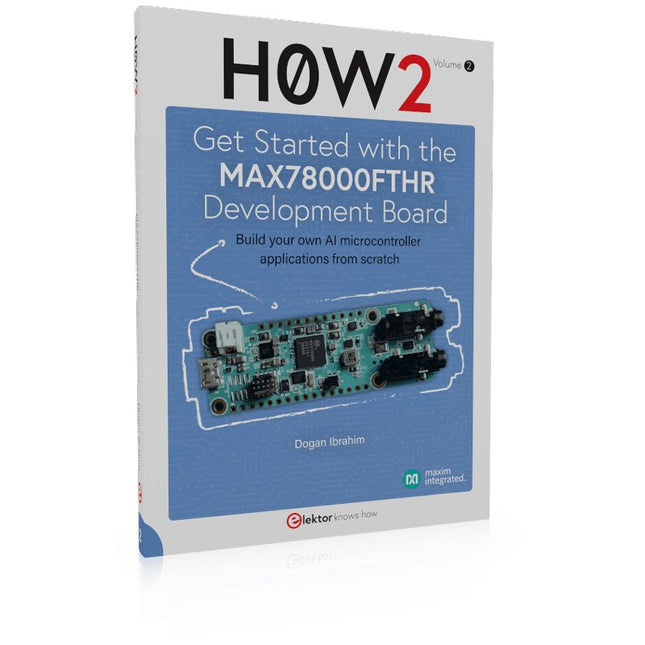
Build your own AI microcontroller applications from scratch
The MAX78000FTHR from Maxim Integrated is a small development board based on the MAX78000 MCU. The main usage of this board is in artificial intelligence applications (AI) which generally require large amounts of processing power and memory. It marries an Arm Cortex-M4 processor with a floating-point unit (FPU), convolutional neural network (CNN) accelerator, and RISC-V core into a single device. It is designed for ultra-low power consumption, making it ideal for many portable AI-based applications.
This book is project-based and aims to teach the basic features of the MAX78000FTHR. It demonstrates how it can be used in various classical and AI-based projects. Each project is described in detail and complete program listings are provided. Readers should be able to use the projects as they are, or modify them to suit their applications. This book covers the following features of the MAX78000FTHR microcontroller development board:
Onboard LEDs and buttons
External LEDs and buttons
Using analog-to-digital converters
I²C projects
SPI projects
UART projects
External interrupts and timer interrupts
Using the onboard microphone
Using the onboard camera
Convolutional Neural Network
As always with Arduino, every element of the platform – hardware, software, and documentation – is freely available and open-source. This means you can learn exactly how it's made and use its design as the starting point for your own circuits. Hundreds of thousands of Arduino Boards are already fueling people’s creativity all over the world, every day. The Arduino Ethernet Shield 2 allows an Arduino Board to connect to the internet. It is based on the Wiznet W5500 Ethernet chip. The Wiznet W5500 provides a network (IP) stack capable of both TCP and UDP. It supports up to eight simultaneous socket connections. Use the Ethernet library to write sketches that connect to the Internet using the Shield. The Ethernet Shield 2 connects to an Arduino Board using long wire-wrap headers extending through the Shield. This keeps the pin layout intact and allows another Shield to be stacked on top of it. The most recent revision of the board exposes the 1.0 pinout on rev 3 of the Arduino UNO Board. The Ethernet Shield 2 has a standard RJ-45 connection, with an integrated line transformer and Power over Ethernet enabled. There is an onboard micro-SD card slot, which can be used to store files for serving over the network. It is compatible with the Arduino Uno and Mega (using the Ethernet library). The onboard micro-SD card reader is accessible through the SD Library. When working with this library, SS is on Pin 4. The original revision of the Shield contained a full-size SD card slot; this is not supported. The Shield also includes a reset controller, to ensure that the W5500 Ethernet module is properly reset on power-up. Previous revisions of the Shield were not compatible with the Mega and needed to be manually reset after power-up.
Easy to solder real time watch kit with a unique laser cut acrylic casing. Four individual acrylic parts cut to fit the internal PCB, battery and switch perfectly. Included is a velcro wrist band. After soldering the Solder:Time, the watch is built by stacking the acrylic parts with the PCB and holding it together with the included screws.
The Solder:Time was designed to be a wrist watch. It doesn't have to be limited to living on your wrist, you could also use it as a badge or desk clock.
Features
Great looking laser cut acrylic case
Unique watch
Easy to solder
Stand alone project – no computer or other programmer required. Just solder it and it's ready!
On board Dallas DS1337+ Real Time Clock (RTC) for super accurate time keeping
Jumper (on bottom) for always on use.
Hackable: Programming and I²C pads labeled on bottom
Clear front and back casing to show the internal electronics
Adjustable wrist band
Can be also be worn as a badge with optional badge clip.
Long lasting battery, with special LED lighting method and very low power processor sleeping.
Included
Solder:Time PCB with all of the electronics
Laser cut acrylic casing with four screws
Easy to use Velcro type wrist band (long enough for huge wrists, trim-able for smaller ones.
CR2032 Battery
Downloads
Documentation
Required
Soldering Iron, solder and wire snips.
Get started with microcontroller based electronics
This Arduino-compatible bundle contains the Motherboard, Digitiser, Sensor Array and RGB Matrix. With these 4 boards you have everything you need to build a clock, score counter, timer, task reminder, thermometer, humidity display, sound meter, light meter, clap trigger, colored bar graph display, animated alarm, and much more!
The Motherboard has a built in real time clock module that keeps time even when unplugged.
The Digitiser can display 4 digits or characters and includes 2 buttons and a potentiometer to let you control what’s being displayed, or the brightness of the display.
The Sensor Array can read temperature, relative humidity, sound and light, with an SD card slot for data recording.
The RGB Matrix has 16 RGB LEDs that are controlled through shift registers, so only use 3 or 4 pins of the Motherboard.
Motherboard
The Motherboard is an Arduino-compatible microcontroller breakout board designed around the ATmega328P. The board comes in a solder-it-yourself kit with all the components you need to get started with microcontroller based electronics. All other boards connect to this.
Based on the ATmega328P
Arduino compatible
On-Board RTC (Real Time Clock)
FTDI Header for easy programming
Bluetooth Header
Terminal Block Connections
Digitiser
The Digitiser is a versatile display and input board. It let’s you visualise your data. Show your sensor information, clock digits, or even keep score for your favourite card game. The Digitiser also includes some buttons and a knob to let you take control.
4x 7-Segment Displays
Uses 595 Shift Registers
2 Switches and a Potentiometer
4 colored 'Mode' LEDs
Chainable with other 595 Boards
Terminal Block Connections
Sensor Array
As the name suggests, the Sensor Array is an array of sensors. Measure temperature and relative humidity via the DHT11, light via the light dependant resistor, and sound via the microphone and amplifier circuit. Then you can log the data using the on-board SD card slot.
DHT11 Temp & Humidity Sensor
Microphone and Amplifier Circuit
Light Dependent Resistor
MicroSD Slot for Saving Data
Logic Level Converter Circuit
Terminal Block Connections
RGB Matrix
Add color to your project by controlling 16 red, 16 green and 16 blue LEDs with just 3 pins of your microcontroller. The RGB Matrix uses shift registers, a matrix and switching transistors, so there’s plenty to learn and explore.
4x4 (16) RGB LEDs
Uses 595 Shift Registers
Chainable with other 595 Boards
Transistor Switches
Terminal Block Connections
Downloads (Manuals)
Motherboard
Digitiser
Sensor Array
RGB Matrix
The OWON HDS2102s is a portable 3-in-1 multifunctional tester, which can be used as a 2-ch oscilloscope with a bandwidth of 100 MHz, multimeter and signal generator. It features a high-contrast 3.5-inch color display suitable for outdoor facility maintenance, rapid on-site measurement, automobile maintenance, power detection. etc.Features
Oscilloscope + multimeter + waveform generator, multifunction in one
3.5-inch high-resolution, high-contrast color LCD display, suitable for outdoor use
18650 lithium battery, can work continuously for 3-6 hours
USB Type-C interface, support power bank, support PC software connection
Self-calibration function
SCPI supported, facilitate secondary development
Specifications
Bandwidth
100 MHz
Channels
2-ch Oscilloscope + 1-ch Generator
Sample Rate
500 MSa/s
Acquisition Model
Normal, Peak detect
Record Length
8K
Display
3.5-inch LCD
Waveform Refresh Rate
10,000 wfrms/s
Input Coupling
DC, AC, and Ground
Input Impedance
1 MΩ ±2%, in parallel with 16pF ±10pF
Probe Attenuation Factors
1X,10X,100X,1000X,10000X
Max. input Voltage
400 V (DC+AC, PK-PK, 1MΩ input impedance) (10:1 probe attenuation)
Bandwidth Limit (typical)
20 MHz
Horizontal Scale
2ns/div - 1000s/div, step by 1 - 2 - 5
Vertical Sensitivity
10mV/div - 10V/div
Vertical Resolution
8 bits
Trigger Type
Edge
Trigger Modes
Auto, Normal, single
Automatic Measurement
Frequency, Period, Amplitude, Max, Min, Mean, PK-PK
Cursor Measurement
ΔV, ΔT, ΔT&ΔV between cursors
Communication Interface
USB-C
Multimeter Specifications
Max. Resolution
20,000 counts
Testing Mode
Voltage, Current, Resistance, Capacitance, Diode, and Continuity test
Input Impedance
10 MΩ
Max Input Voltage
AC 750 V, DC 1000 V
Max Input Current
DC: 10 A, AC: 10 A
Diode
0-2 V
Waveform Generator Specifications
Frequency Output
Sine
0.1 Hz - 25 MHz
Square
0.1 Hz - 5MHz
Ramp
0.1 Hz - 1 MHz
Pulse
0.1 Hz - 5 MHz
Arbitrary
0.1 Hz - 5 MHz
Sampling Rate
125 MSa/s
Channel
1-ch
Amplitude Range (high impedance)
20 mVpp - 5 Vpp
Waveform Length
8K
Vertical Resolution
14 bits
Output Impedance
50Ω
Included
1x OWON HDS2102s
1x Power adapter
1x USB cable
1x Passive probes
2x Crocodile clip cable
1x Set of multimeter probes (one red and one black)
1x User manual
1x Probe correction adjustment knife
Downloads
User Manual
Specifications
SCPI Protocol
Quick Guide
Software
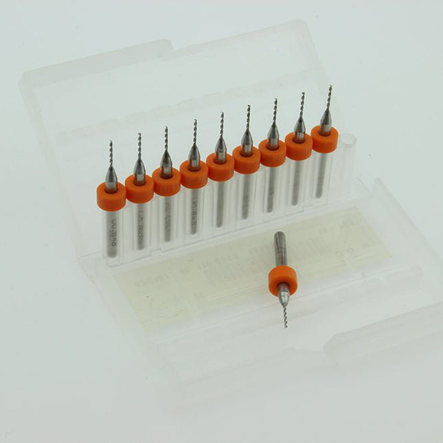
Cleaning nozzle drill kit small box containing 10 carbide PCB drills 0.8 mm all with 4 mm shaft.
Ideal for drilling small precision holes in pcb's, plastic or soft metal.
The GTMEDIA V8 Finder2 is a handheld satellite meter that supports DVB-S/S2 and MPEG-2/4 H.264 (8-bit) standards. Designed for convenience, it boasts a compact size, lightweight build, user-friendly interface, extended battery life, and a comprehensive set of features.
This meter provides all the essential functions needed for efficient installation and verification of digital satellite TV services, whether for individual residences or multi-dwelling units.
Specifications
Frequency Range
950-2150 MHz
DC IN
13 V/18 V (max 350 mA)
Display
3.5" HD TFT LCD Screen (320 x 240)
Standard
DVB-S/S2/S2X
Battery
Built-in 7.4 V/4000 mAh Lithium battery
Dimensions
95 x 155 x 45 mm
Weight
450 g
Included
GTmedia V8 Finder 2
USB cable
Manual
Celebrating the Arduino Uno with a miniaturized limited edition
The world's favorite development board has gone mini. Everything in this version of the Arduino Uno is unique. Black and gold, finishing, elegant design and packaging, all delivered to the highest standard. A little jewel to celebrate the Arduino community and what we’ve been doing together for all these years.
Each item is unique and numbered on the PCB, and includes a hand-signed letter from the founders. It’s a limited edition, so get while it’s in stock!
For serious Arduino Uno lovers
Arduino Uno Mini Limited Edition is a collector’s item for serious Arduino Lovers: hobbyists, students, makers, reimaginers, dreamers, hopers, fans, engineers, designers, questioners, cake-makers, problem-solvers, puzzlers, gamers, debaters, developers, entrepreneurs, architects, future-shapers, musicians, scientists... 10 million projects based on (official) Uno boards that have contributed to this incredible story.
Specifications
The Arduino Uno Mini Limited Edition is a microcontroller board based on the ATmega328P. It has 14 digital inputs/outputs (six of which can be used as PWM outputs), six analog inputs, a 16 MHz ceramic resonator, a USB-C connector, and a reset button. Contains everything needed to support the microcontroller. Simply connect it to a computer with a USB cable, use a power adapter, or connect a battery to get started.
Microcontroller
ATmega328P
USB connector
USB-C
Built-in LED Pins
13
Digital I/O Pins
14
Analog Input Pins
6
PWM Pins
6
UART
Yes
I²C
Yes
SPI
Yes
Circuit operating voltage
5 V
Input Voltage (limit)
6-12 V
Battery connector
None
DC current per I/O Pin
20 mA
DC current for 3.3 V Pin
50 mA
Main processor
ATmega328P (16 MHz)
USB-serial processor
ATmega16U2 (16 MHz)
Memory ATmega328P
2 KB SRAM, 32 KB Flash, 1 KB EEPROM
Weight
8.05 g
Dimensions
26.70 x 34.20 mm
Downloads
Datasheet
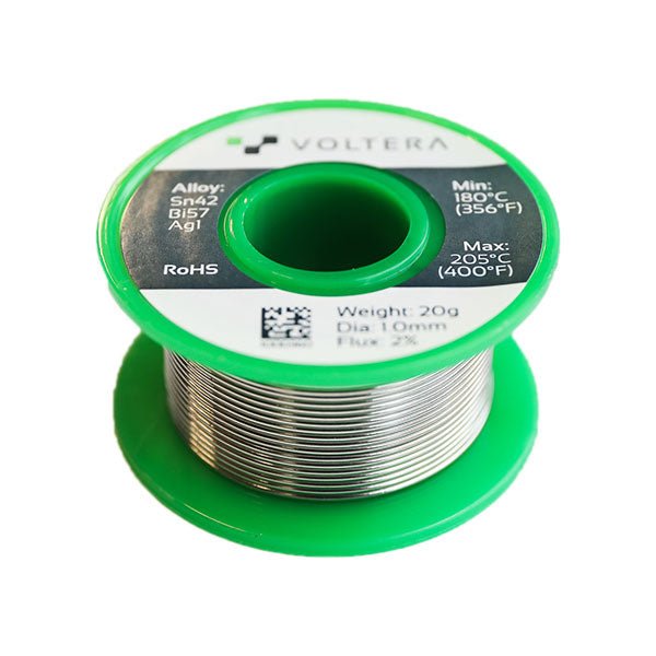
Done printing? Let’s add some components! Just be sure to use the Voltera recommended solder wire and plenty of flux to ensure a strong solder joint. Voltera has chemically tested it to be most compatible with their ink.
Alloy: Sn42 Bi57 Ag1
Dia: 1.0 mm
Flux: 2%
Weight: 20g
Recommended Temp: < 205°C (400°F)
RoHS Compliant
The Pico-10DOF-IMU is an IMU sensor expansion module specialized for Raspberry Pi Pico. It incorporates sensors including gyroscope, accelerometer, magnetometer, baroceptor, and uses I²C bus for communication. Combined with the Raspberry Pi Pico, it can be used to collect environment sensing data like temperature and barometric pressure, or to easily DIY a robot that detects motion gesture and orientation. Features Standard Raspberry Pi Pico header, supports Raspberry Pi Pico series Onboard ICM20948 (3-axis gyroscope, 3-axis accelerometer, and 3-axis magnetometer) for detecting motion gesture, orientation, and magnetic field Onboard LPS22HB barometric pressure sensor, for sensing the atmospheric pressure of the environment Comes with development resources and manual (Raspberry Pi Pico C/C++ and MicroPython examples) Specifications Operating voltage 5 V Accelerometer Resolution: 16-bitMeasuring range (configurable): ±2, ±4, ±8, ±16gOperating current: 68.9uA Gyroscope Resolution: 16-bitMeasuring range (configurable): ±250, ±500, ±1000, ±2000°/secOperating current: 1.23mA Magnetometer Resolution: 16-bitMeasuring range: ±4900µTOperating current: 90uA Baroceptor Measuring range: 260 ~ 1260hPaMeasuring accuracy (ordinary temperature): ±0.025hPaMeasuring speed: 1Hz - 75Hz
STEMTera is a programmable breadboard module, compatible with Arduino Uno. It has two microcontrollers built in: ATmega328P and ATmega32U2 and the I/O (40 mA per pin) are accessible without cabling.
The underside of the board (112 x 80 x 17 mm) is compatible with LEGO.
Specifications
Pin-to-pin compatible with Arduino Uno
Mechanically compatible with LEGO blocks
Two microcontrollers (41 I/O of which 9 as PWM)
USB interface with ATmega32U2 using LUFA (Lightweight USB Framework for AVRs) for keyboard, joystick, MIDI, etc...
Programming with the Arduino IDE (micro-USB)
Reset button, 4 LEDs (including TX, RX, Power), power connector
Power via micro-USB or 7...20 V DC on socket 5,5 x 2,1 mm (+ center)
Multiple programming environments:
Atmel Studio
Arduino IDE
AVR-GCC
AVR-GCC with LUFA library
Scratch
etc.
Microcontrollers
ATmega328P:
14 pins of I/O including 6 PWM
6 analog inputs (10 bit ADC)
I²C, SPI and serial
Interrupt controller
ATmega32U2:
21 pins of I/O
Flash Memory: 32 KB
SRAM: 2 KB
EEPROM: 1 KB
Clock: 16 MHz
Downloads
Beginner's Guide
The SEQURE ES666 is a smart electric screwdriver designed for precision tasks such as assembling and disassembling electronics, RC models, drones, and more.
It features multiple operation modes: Sensing Mode, Fixed Mode, and Automatic Mode, allowing for versatile use. The device includes an OLED display and a 600 mAh rechargeable battery providing up to 4 hours of no-load operation.
Features
Smart Control: Supports angle sensing control and adjustable sensitivity. It starts and stops automatically for hands-free operation, and stops automatically when the screw is fully tightened.
Enhanced Visibility: Equipped with front-facing shadowless LED lights with on/off and delay modes.
Robust Design: Constructed with a metal shell and anti-slip strips for a secure grip that prevents rolling.
High-Quality Bits: Includes durable S2 steel bits with built-in strong magnets for fast screw assembly and disassembly.
Powerful Performance: Features a metal gear reduction motor and a built-in high-capacity battery for stable, continuous use.
Smart Display: Comes with a dynamic multi-functional UI interface and supports firmware upgrades.
Versatile Use: Offers 7 torque settings to suit a variety of tasks – ideal for repairing, assembling, or disassembling RC models, drones, mobile phones, computers, watches, glasses, and other electronics.
Specifications
Manual Torque
22kgf.cm / 2.2N.m
Torque Gears
7
Battery
600 mAh
No-load Speed
250 rpm
Working Time
No-load 4h
Charging
USB-C 5 V
Bits
4 mm Hexagon
Display
128 x 32 OLED
Front Lighting
LED
Working Modes
Sensing, Fixed, Automatic
Firmware Upgrades
Yes
Menu Languages
English, Russian, and Chinese
Dimensions
15 x 16 x 140 mm
Weight (Screwdriver)
57 g
Included
1x SEQURE ES666 Electric Screwdriver
30x Magnetic S2 steel bits
1x USB-C charging cable
1x Carrying case
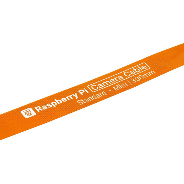
Raspberry Pi 5 provides two four-lane MIPI connectors, each of which can support either a camera or a display. These connectors use the same 22-way, 0.5 mm-pitch “mini” FPC format as the Compute Module Development Kit, and require adapter cables to connect to the 15-way, 1 mm-pitch “standard” format connectors on current Raspbery Pi camera and display products.These mini-to-standard adapter cables for cameras and displays (note that a camera cable should not be used with a display, and vice versa) are available in 200 mm, 300 mm and 500 mm lengths.
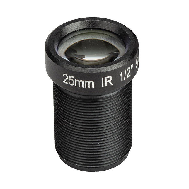
The M12 Mount Lens (5 MP, 25 mm) is ideal for use with the Raspberry Pi HQ Camera Module, offering sharp and detailed imaging for a wide range of applications.
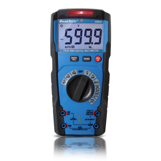
The PeakTech 3350 was specially developed for use in the craftsmanship and industry and offers a variety of useful functions that simplify daily work, especially in dark or noisy environments. The lighting of the large LCD display is automatically activated by a photodiode in dark surroundings. On the back of the device there is also a bright LED flashlight, which is used to illuminate the area where the measurement has to be taken. A multi-colored LED bar is located above the 6000-digit display. Depending on the active measuring function, it lights up green during the continuity test, red when a voltage is found in NCV mode, yellow when measuring large capacities or flashes red when the phase tester mode is active (LIVE).
The PeakTech 3350 was manufactured according to the latest development aspects and has a double-insulated injection-molded housing with rubber coating, a tilt stand on the back, which can be removed to replace the batteries. The fuses are located underneath the stand as well, if it is neccessary to replace these. With this device the measuring range is selected automatically, which enable particularly fast response times.
Features
True RMS voltage up to 600 V and current up to 10 A AC/DC
6,000 LCD display with automatic backlight
Multi-colored warning LED for various measuring functions
Automatic range selection
Manual range selection possible using selection buttons
Integrated LED flashlight for lighting the area where the measurement has to be taken
Auto off and battery status display
Safety: EN 61010-1; CAT III 600 V
Accessories: bag, test leads, temperature sensor, temperature adapter, batteries and user manual
Specifications
Basic Accuracy DC
±0.5%
Battery
1.5 V AAA
Capacitance max.
60 mF
Digital counts
6000
Display Type
LCD
Info LEDs
■
LED lamp
■
NCV
■
Over voltage category
CAT III 600 V
Range selection
Auto
True RMS
■
V DC max.
600 V
A AC max.
10 A
Hz max.
10 MHz
OHM max.
60 MΩ
Temp. max.
1000°C
Temp. min.
-18°C
mA DC max.
600 mA
mV DC max.
600 mV
µA DC max.
6000 µA
V AC max.
600 V
mV AC max.
600 mV
A DC max.
10 A
mA AC max.
600 mA
µA AC max.
6000 µA
Downloads
Manual
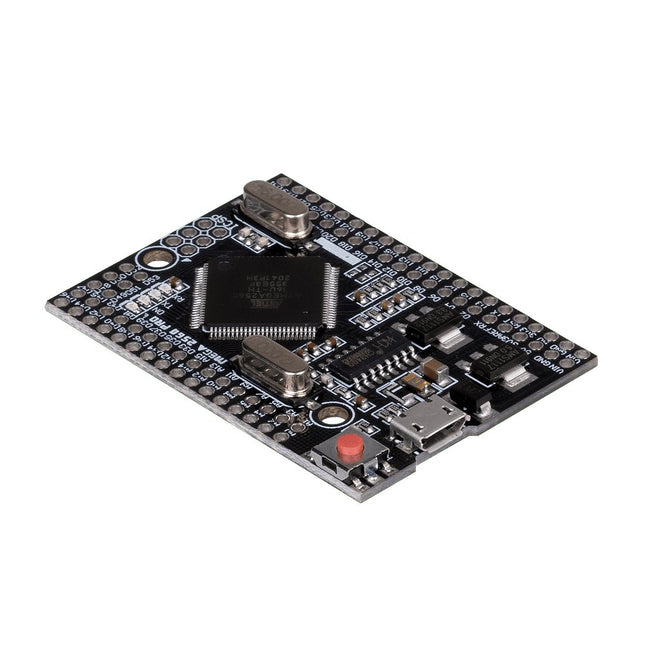
This JOY-iT microcontroller board opens the world of programming to you and offers you the same computing power as the Mega 2560, but with a smaller foot-print. It also has many more connectors than comparable boards (Arduino Uno). It is powered by the Arduino IDE and power can be supplied either via the USB port or the VIN pins. This allows you to use it safely with many other devices, e.g. desktop PC. Therefore the Mega 2560 Pro is highly integrable.
Features
Microcontroller
ATmega2560 - 16AU
Storage
Flash 256 KB, SRAM 8 KB, EEPRom 4 KB
Amount of Pins:Digital I/OPWM OutputAnalog Input
541516
Compatible with
Arduino, Desktop PCs, etc.
Special features
USB Port or Power Pins for power supply
Interface converter
Micro USB to USB UART
Size
55 x 38 mm
Items delivered
JOY-iT Mega 2560 Pro with Pins
Further Specifications
Input Voltage
7 - 9 Volt on Vin, 5 Volt on mUSB
Logic level
5 Volt
Output current
800 mA
Voltage regulator
LDO (for up to 12 V peak)
Frequency
16 MHz (12 MHz are possible for data exchange)
Downloads
Manual
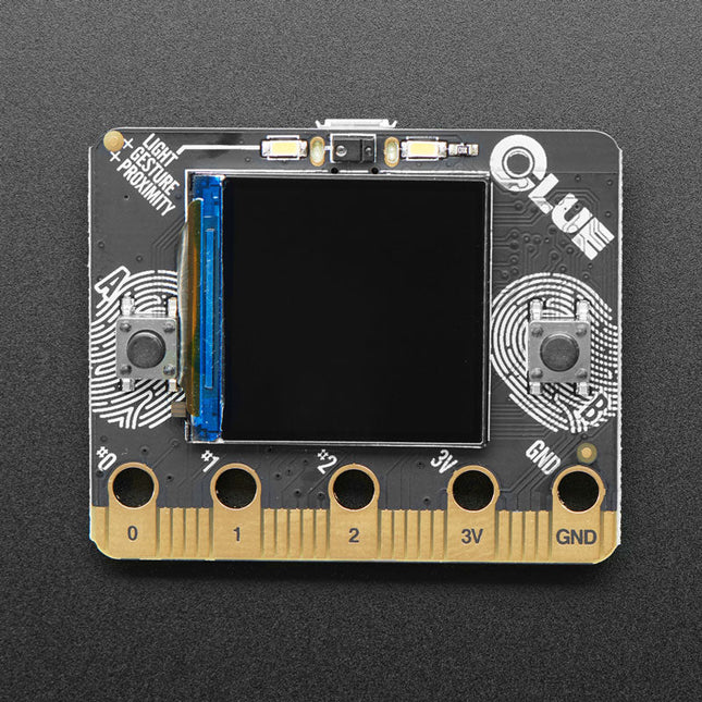
Features
Nordic nRF52840 Bluetooth LE processor – 1 MB of Flash, 256KB RAM, 64 MHz Cortex M4 processor
1.3″ 240×240 Color IPS TFT display for high-resolution text and graphics
Power it from any 3-6V battery source (internal regulator and protection diodes)
Two A / B user buttons and one reset button
ST Micro series 9-DoF motion – LSM6DS33 Accel/Gyro + LIS3MDL magnetometer
APDS9960 Proximity, Light, Color, and Gesture Sensor
PDM Microphone sound sensor
SHT Humidity
BMP280 temperature and barometric pressure/altitude
RGB NeoPixel indicator LED
2 MB internal flash storage for datalogging, images, fonts or CircuitPython code
Buzzer/speaker for playing tones and beeps
Two bright white LEDs in front for illumination / color sensing
Qwiic / STEMMA QT connector for adding more sensors, motor controllers, or displays over I²C. You can plug in GROVE I²C sensors by using an adapter cable.
Programmable with Arduino IDE or CircuitPython
This desk lamp is ideal for your workplace. With the 5-inch 5D-lens, the finest work can be done. The lamp has 80 integrated LEDs.
Features
Lens size: 5 inch
Lens material: glass
Diopter: 5D
Light source: T5 22 W fluorescent energy-saving bulb (80pcs LED)
Standard mount: table base
Voltage: 220-240 V
Power: 22 W
The SQ series of handsfree PCBite probes from Sensepeek are insulated, come with included color-coded cable holders and have a lower point of gravity making them even more stable compared with the original SP series of probes. All the loved features of handsfree measurement, exchangeable fine pitch spring tipped test needle and the minimalistic design is maintained to make traditional sized and handheld probes obsolete. Features All handsfree probes from Sensepeek makes instant measurements or long triggering sessions a breeze. No more soldering wires to connect your probe or complicated tools to setup, just positioning the probe needle on any test point or component in the signal path and release. Saves time and frustration during development, verification and repairs. The minimalist design and the spring-loaded test needle makes it possible to simultaneously measure on fine pitch components and nearby signals. Both length and weight of the SQ probes are perfectly balanced to be used with PCBite PCB holders and base plate which is a must for handsfree function. The probe holder comes with a powerful magnet in the base, as for all PCBite probes and holders which makes the probe easy to place and reposition. The SQ series of probes can be used handheld without the probe holder as they have an insulated grip but their full potential is used when measuring handsfree. Included 2x SQ10 probes and pin tipped test needles (red/black) 2x Banana to dupont test wires (red/black) 1x Set of cable holders (red/black) 2x Extra test needles Downloads User guide
The Raspberry Pi 500 (based on the Raspberry Pi 5) features a quad-core 64-bit Arm processor, RP1 I/O controller, 8 GB RAM, wireless networking, dual-display output, 4K video playback, and a 40-pin GPIO header. It's a powerful, compact all-in-one computer built into a portable keyboard.
The built-in aluminum heatsink provides improved thermal performance, allowing the Raspberry Pi 500 to run quickly and smoothly even under heavy load.
Specifications
SoC
Broadcom BCM2712
CPU
ARM Cortex-A76 (ARM v8) 64-bit
Clock rate
4x 2.4 GHz
GPU
VideoCore VII (800 MHz)
RAM
8 GB LPDDR4X (4267 MHz)
WiFi
IEEE 802.11b/g/n/ac (2.4 GHz/5 GHz)
Bluetooth
Bluetooth 5.0, BLE
Ethernet
Gigabit Ethernet (with PoE+ support)
USB
2x USB-A 3.0 (5 GBit/s)1x USB-A 2.01x USB-C (for power supply)
PCI Express
1x PCIe 2.0
GPIO
Standard 40-pin GPIO header
Video
2x micro-HDMI ports (4K60)
Multimedia
H.265 (4K60 decode)OpenGL ES 3.1, Vulkan 1.2
SD card
microSD
Power supply
5 V DC (via USB-C)
Keyboard layout
US (QWERTY)
Dimensions
286 x 122 x 23 mm
Downloads
Datasheet
The set consists of 86 pieces. These are a Mega 2560 microcontroller board, 2 breadboards, one USB cable, a battery holder, an IR remote control, one 4-digit segment display, 2x 1-digit segment displays, one 8x8 LED matrix, a potentiometer, one RGB LED, 5 blue LEDs, 5 yellow LEDs, 5 red LEDs, 4 buttons,a temperature sensor (LM35), 2 tilt switches, an IR receiver, one active buzzer, one passive buzzer, 3 photo resistors, a flame sensor, 18 resistors (5x 1 kΩ, 8x 220 Ω, 5x 10 kΩ), a shift register (SN74HC595N) and 30 cables. Features Model Mega 2560 Learning Kit Microcontroller ATmega 2560 R3 Projects 20 different projects Manual Incl. project manual of 63 pages as download and a printed quick reference guide Specifications Input Voltage 7-12 V Ipput Voltage (max.) 6-20 V Digital IO 54 (14 with PWM) Analog IO 16 DC Current IO 40 mA DC Current 3.3 V 50 mA Memory 256 kB (8 kB Bootloader) SRAM 8 kB EEPROM 4 kB Clock Speed 16 MHz Dimensions 11.52 x 53,3 mm