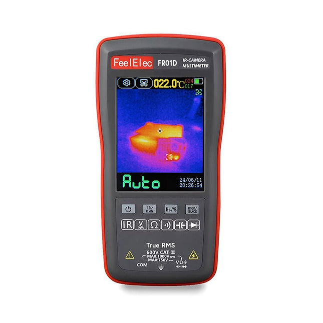
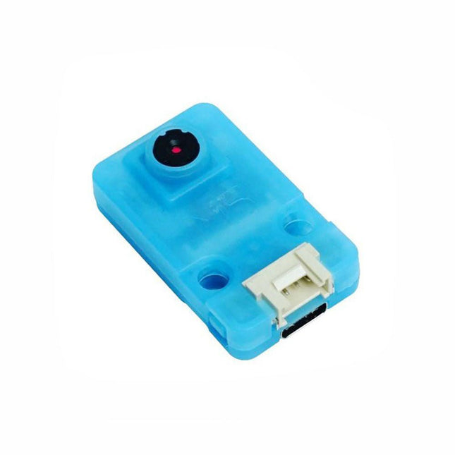
The FR01D (2-in-1) thermal imaging camera and multimeter is a compact and lightweight solution that simplifies diagnostic and maintenance tasks. The one-click function allows you to switch effortlessly between thermal imaging and multimeter mode, giving you two important tools in one portable device.
The multimeter is capable of measuring DC and AC voltage, resistance, diode checks, continuity testing, and capacitance.
The FR01D has a 2.8-inch touchscreen with a resolution of 320 x 480 pixels. The device is powered by an integrated rechargeable lithium battery and can be charged via USB.
With the FR01D, you can inspect and maintain circuit boards, check power supplies, repair electronic devices, and overhaul household appliances. Its compact size, multifunctionality, and user-friendliness make the FR01D the ideal companion for electronics and maintenance technicians.
General Specifications
Display size
2.8" (320 x 480)
Touchscreen
Resistive
Data transmission
USB-C
Image storage format
BMP
Battery
Li-ion battery
Storage temperature
−20°C~60°C(−4°F~140°F)
Operating temperature
0°C~50°C(32°F~122°F)
Operating humidity
<85% RH
Dimensions
134 x 69 x 25 mm
Weight
130 g
Thermal Imaging Specifications
Sensor
Vanadium oxide (VOx)
Image capture frequency
25 Hz
Thermal imaging pixels
192 x 192
Field of View (FOV)
50.0°(H) x 50°(V) / 72.1°(D)
Temperature range
−20°C ~ +550°C (−4°F~1022°F)
Gain mode
Auto
Accuracy
±2°C or ±2%
Measurement resolution
0.1°C / 0.1°F
Multimeter Specifications
DC input voltage (max.)
1000 V
AC input voltage (max.)
750 V
Resistance (max.)
99.99 MΩ
Capacitance (max.)
99.99 mF
Duty cycle test range
0.1% ~ 99.9%
Diode test range
0 V ~ 3 V
Continuity test
999.9 Ω
Display
9999 counts (Refreshes 3x per second)
Accuracy
Function
Range
Resolution
Accuracy
AC Voltage
400 mV
0.1 mV
2% +3
9.999 V
0.001 V
1.0% +3
99.99 V
0.01 V
999.9 V
0.1V
DC Voltage
400 mV
0.1 mV
2% +3
9.999 V
0.001 V
1.0% +3
99.99 V
0.01 V
999.9 V
0.1 V
Resistance
999.9 Ω
0.1 Ω
0.5% +3
9.999 KΩ
0.001 kΩ
99.99 KΩ
0.01 kΩ
999.9 KΩ
0.1 kΩ
9.999 MΩ
0.001 MΩ
99.99 MΩ
0.01 MΩ
1.5% +3
Diode Test
3.000 V
0.001 V
10%
Capacitance
9.999 nF
0.001 nF
2% +5
99.99 nF
0.01 nF
999.9 nF
0.1 nF
9.999 uF
0.001 uF
99.99 uF
0.01 uF
999.9 uF
0.1 uF
9.999 mF
0.001 mF
5% +5
99.99 mF
0.01 mF
Included
1x FR01D IR-Camera and Multimeter
2x Test Leads
1x USB Cable
1x Manual
Additionally, this u-blox receiver supports I²C (u-blox calls this Display Data Channel), making it perfect for the Qwiic compatibility, so we don't have to use up our precious UART ports. Utilizing our handy Qwiic system, no soldering is required to connect it to the rest of your system. However, we still have broken out 0.1'-spaced pins if you prefer to use a breadboard.
The NEO-M9N module detects jamming and spoofing events and can reports them to the host so that the system can react to such events. A SAW (Surface Acoustic Wave) filter combined with an LNA (Low Noise Amplifier) in the RF path is integrated into the NEO-M9N module, allowing normal operation even under strong RF interferences.
U-blox based GPS products are configurable using the popular but dense, windows program called u-centre. Plenty of different functions can be configured on the NEO-M9N: baud rates, update rates, geofencing, spoofing detection, external interrupts, SBAS/D-GPS, etc. All of this can be done within the SparkFun Arduino Library!
The SparkFun NEO-M9N GPS Breakout is also equipped with an on-board rechargeable battery that provides power to the RTC on the NEO-M9N. This reduces the time-to-first fix from a cold start (~24s) to a hot start (~2s). The battery will maintain RTC and GNSS orbit data without being connected to power for plenty of time.
Features
Integrated U.FL connector for use with an antenna of your choice
92-Channel GNSS Receiver
1.5 m Horizontal Accuracy
25 Hz Max Update Rate (4 concurrent GNSS)
Time-To-First-Fix:
Cold: 24 s
Hot: 2 s
Max Altitude: 80,000 m
Max G: ≤ 4
Max Velocity: 500 m/s
Velocity Accuracy: 0.05 m/s
Heading Accuracy: 0.3 degrees
Time Pulse Accuracy: 30 ns
3.3 V VCC and I/O
Current Consumption: ~31 mA Tracking GPS+GLONASS
Software Configurable
Geofencing
Odometer
Spoofing Detection
External Interrupt
Pin Control
Low Power Mode
Many others!
Supports NMEA, UBX, and RTCM protocols over UART or I²C interfaces
Downloads
Schematic
Eagle Files
Board Dimensions
Hookup Guide
Building a GPS System
Datasheet (NEO-M9N)
Product Summary
Integration Manual
u-blox Protocol Specification
NEO-M9M Documents & Resources
u-center Software
SparkFun u-blox GNSS Arduino Library
GitHub Hardware Repo
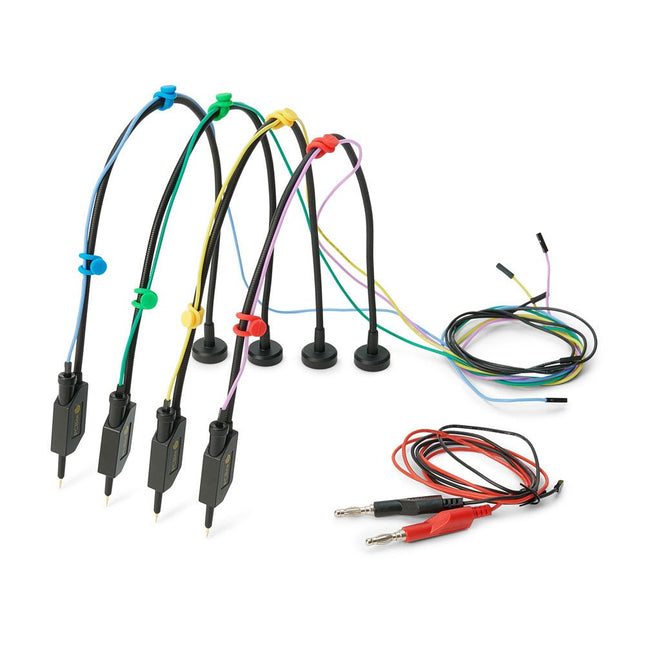
The SQ series of handsfree PCBite probes from Sensepeek are insulated, come with included color-coded cable holders and have a lower point of gravity making them even more stable compared with the original SP series of probes. All the loved features of handsfree measurement, exchangeable fine pitch spring tipped test needle and the minimalistic design is maintained to make traditional sized and handheld probes obsolete. Features All handsfree probes from Sensepeek makes instant measurements or long triggering sessions a breeze. No more soldering wires to connect your probe or complicated tools to setup, just positioning the probe needle on any test point or component in the signal path and release. Saves time and frustration during development, verification and repairs. The minimalist design and the spring-loaded test needle makes it possible to simultaneously measure on fine pitch components and nearby signals. Both length and weight of the SQ probes are perfectly balanced to be used with PCBite PCB holders and base plate which is a must for handsfree function. The probe holder comes with a powerful magnet in the base, as for all PCBite probes and holders which makes the probe easy to place and reposition. The SQ series of probes can be used handheld without the probe holder as they have an insulated grip but their full potential is used when measuring handsfree. Included 4x SQ10 probes and pin tipped test needles (black) 2x Banana to dupont test wires (red/black) 5x Dupont to dupont test wires 1x Set of cable holders (4 colors) 4x Extra test needles Downloads User guide
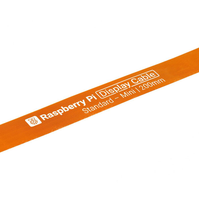
Raspberry Pi 5 provides two four-lane MIPI connectors, each of which can support either a camera or a display. These connectors use the same 22-way, 0.5 mm-pitch “mini” FPC format as the Compute Module Development Kit, and require adapter cables to connect to the 15-way, 1 mm-pitch “standard” format connectors on current Raspbery Pi camera and display products.These mini-to-standard adapter cables for cameras and displays (note that a camera cable should not be used with a display, and vice versa) are available in 200 mm, 300 mm and 500 mm lengths.
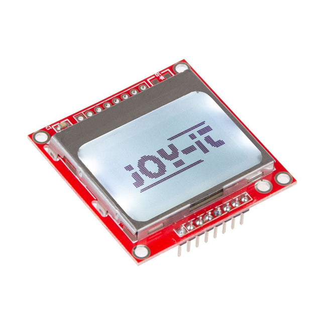
This display correspond to the Nokia 5110 norm which makes it perfectly to display data or graphs of measured values on a microcontroller or a single-board computer. Additionally, the display is compatible to all Raspberry Pi, Arduino, CubieBoard, Banana Pi and microcontroller without additional effort. Specifications Chipset Philips PCD8544 Interface SPI Resolution 84 x 48 Pixels Power supply 2.7-3.3 V Special features Backlight Compatible to Raspberry Pi, Arduino, CubieBoard, Banana Pi and microcontroller Dimensions 45 x 45 x 14 mm Weight 14 g
The FNIRSI CTG-20 is a coating thickness gauge designed for measuring the thickness of electroplated coatings or coatings on metal surfaces. It can accurately measure non-magnetic coatings (such as paint) on magnetic materials like steel or iron, as well as coatings on non-magnetic materials such as aluminum.
Equipped with a built-in precision probe and a rechargeable lithium battery, the device automatically detects substrate properties and determines coating thickness using electromagnetic induction and eddy current effects. This robust instrument delivers fast and highly accurate measurements, making it ideal for applications in manufacturing, the chemical industry, the automotive sector, and other testing fields.
Specifications
Measuring Range
0-1400 μm
Accuracy
±3% +2 μm
Resolution Ratio
0.1 μm
Calibration
Zero point calibration, Multi-point calibration
Unit
μm, mil
Minimum Convex Curvature Radius
5 mm
Minimum Convex Curvature Radius
25 mm
Minimum measurement area diameter
20 mm
Battery
600 mAh Lithium battery
Charging Interface
USB-C
Features
Data Storage, Rotatable Screen, Putty Powder Test, Auto Power Off
Dimensions
115 x 48 x 18 mm
Weight
83 g
Included
1x FNIRSI CTG-20 Coating Thickness Gauge
1x USB cable
1x Manual
Downloads
Manual
The SparkFun GPS-RTK2 raises the bar for high-precision GPS and is the latest in a line of powerful RTK boards featuring the ZED-F9P module from u-blox. The ZED-F9P is a top-of-the-line module for high accuracy GNSS and GPS location solutions, including RTK capable of 10 mm, three-dimensional accuracy. With this board, you will be able to know where your (or any object's) X, Y, and Z location is within roughly the width of your fingernail! The ZED-F9P is unique in that it is capable of both rover and base station operations. Utilizing our handy Qwiic system, no soldering is required to connect it to the rest of your system. However, we still have broken out 0.1"-spaced pins if you prefer to use a breadboard.
We've even included a rechargeable backup battery to keep the latest module configuration and satellite data available for up to two weeks. This battery helps 'warm-start' the module decreasing the time-to-first-fix dramatically. This module features a survey-in mode allowing the module to become a base station and produce RTCM 3.x correction data.
The number of configuration options of the ZED-F9P is incredible! Geofencing, variable I²C address, variable update rates, even the high precision RTK solution can be increased to 20 Hz. The GPS-RTK2 even has five communications ports which are all active simultaneously: USB-C (which enumerates as a COM port), UART1 (with 3.3 V TTL), UART2 for RTCM reception (with 3.3V TTL), I²C (via the two Qwiic connectors or broken out pins), and SPI.
Sparkfun has also written an extensive Arduino library for u-blox modules to easily read and control the GPS-RTK2 over the Qwiic Connect System. Leave NMEA behind! Start using a much lighter weight binary interface and give your microcontroller (and its one serial port) a break. The SparkFun Arduino library shows how to read latitude, longitude, even heading and speed over I²C without the need for constant serial polling.
Features
Concurrent reception of GPS, GLONASS, Galileo and BeiDou
Receives both L1C/A and L2C bands
Voltage: 5 V or 3.3 V, but all logic is 3.3 V
Current: 68 mA - 130 mA (varies with constellations and tracking state)
Time to First Fix: 25 s (cold), 2 s (hot)
Max Navigation Rate:
PVT (basic location over UBX binary protocol) - 25 Hz
RTK - 20 Hz
Raw - 25 Hz
Horizontal Position Accuracy:
2.5 m without RTK
0.010 m with RTK
Max Altitude: 50k m
Max Velocity: 500 m/s
2x Qwiic Connectors
Dimensions: 43.5 x 43.2 mm
Weight: 6.8 g
The Raspberry Pi Monitor is a 15.6-inch Full HD computer display. User-friendly, versatile, compact and affordable, it is the perfect desktop display companion for both Raspberry Pi computers and other devices.
With built-in audio via two front-facing speakers, and VESA and screw mounting options as well as an integrated angle-adjustable stand, the Raspberry Pi Monitor is ideal for desktop use or for integration into projects and systems. It can be powered directly from a Raspberry Pi, or by a separate power supply.
Features
15.6-inch full HD 1080p IPS display
Integrated angle-adjustable stand
Built-in audio via two front-facing speakers
Audio out via 3.5 mm jack
Full-size HDMI input
VESA and screw mounting options
Volume and brightness control buttons
USB-C power cable
Specifications
Display
Screen size: 15.6 inches, 16:9 ratio
Panel type: IPS LCD with anti-glare coating
Display resolution: 1920 x 1080
Color depth: 16.2M
Brightness (typical): 250 nits
Color gamut: 45%
Viewing angle: 80°
Power
1.5 A/5 V
Can be powered directly from a Raspberry Pi USB port (max 60% brightness, 50% volume) or by a separate power supply (max 100% brightness, 100% volume)
Connectivity
Standard HDMI port (1.4 compliant)
3.5 mm stereo headphone jack
USB-C (power in)
Audio
2x 1.2 W integrated speakers
Support for 44.1 kHz, 48 kHz, and 96 kHz sample rates
Downloads
Datasheet
OV7740 is a AI Camera powered by Kendryte K210, an edge computing system-on-chip(SoC) with a dual-core 64bit RISC-V CPU and state-of-art neural network processor.
Features
Dual-Core 64-bit RISC-V RV64IMAFDC (RV64GC) CPU / 400Mhz(Normal)
Dual Independent Double Precision FPU
8MiB 64bit width On-Chip SRAM
Neural Network Processor(KPU) / 0.8Tops
Field-Programmable IO Array (FPIOA)
AES, SHA256 Accelerator
Direct Memory Access Controller (DMAC)
Micropython Support
Firmware encryption support
On-board Hardware:
Flash: 16M Camera :OV7740
2x Buttons
Status Indicator LED
External storage: TF card/Micro SD
Interface: HY2.0/compatible GROVE
Applications
Face recognition/detection
Object detection/classification
Obtain the size and coordinates of the target in real-time
Obtain the type of detected target in real-time
Shape recognition Video recorder
Included
1x UNIT-V(include 20cm 4P cable and USB-C cable)
If you are searching for a possibility to keep your Raspberry Pi cool, than this mini fan is the perfect possibility for this. The active cooler is ready to use right after pluging in the two GPIO pins into the 5V and GND GPI-O port. The cooler is compatible to all Raspberry Pis and is perfect to keep them cool, even under full load. Voltage: 5 V Current: 0.2 A Dimensions: 30 x 30 x 7 mm
The full-color, spiral-bound SIK guidebook (included) contains step-by-step instructions with circuit diagrams and hookup tables for building each project and circuit with the included parts. Full example code is provided, new concepts and components are explained at the point of use, and troubleshooting tips offer assistance if something goes wrong.
The kit does not require any soldering and is recommended for beginners ages 10 and up looking for an Arduino starter kit. For SIK version 4.1, Sparkfun took an entirely different approach to teaching embedded electronics. In previous versions of the SIK, each circuit focused on introducing a new piece of technology. With SIK v4.1, components are introduced in the context of the circuit you are building. Each circuit builds upon the last, leading up to a project that incorporates all of the components and concepts introduced throughout the guide. With new parts and a completely new strategy, even if you've used the SIK before, you're in for a brand-new experience!
The SIK V4.1 includes the Redboard Qwiic, which allows you to expand into the SparkFun Qwiic ecosystem after becoming proficient with the SIK circuits. The SparkFun Qwiic Connect System is an ecosystem of I²C sensors, actuators, shields and cables that make prototyping faster and less prone to error. All Qwiic-enabled boards use a common 1mm pitch, 4-pin JST connector. This reduces the amount of required PCB space, and polarized connections mean you can’t hook it up wrong. With the addition of the SparkFun RedBoard Qwiic, you will need to download a new driver install that is different from the original SparkFun RedBoard.
Included
SparkFun RedBoard Qwiic
Arduino and Breadboard Holder
SparkFun Inventor's Kit Guidebook
White Solderless Breadboard
Carrying Case
SparkFun Mini Screwdriver
16 x 2 White-on-Black LCD (with headers)
SparkFun Motor Driver (with Headers)
Pair of Rubber Wheels
Pair of Hobby Gearmotors
Small Servo
Ultrasonic Distance Sensor
TMP36 Temp Sensor
6' USB Micro-B Cable
Jumper Wires
Photocell
Tricolour LED
Red, Blue, Yellow and Green LEDs
Red, Blue, Yellow and Green Tactile Buttons
10K Trimpot
Mini Power Switch
Piezo Speaker
AA Battery Holder
330 and 10K Resistors
Binder Clip
Dual-Lock Fastener
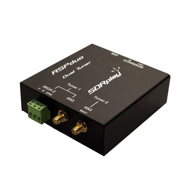
The SDRplay RSPduo is a high performance dual-tuner 14-bit SDR receiver. Housed in a high quality steel enclosure, each tuner can operate individually anywhere between 1 kHz and 2 GHz with up to 10 MHz of bandwidth or both tuners can operate simultaneously anywhere between 1 kHz and 2 GHz with up to 2 MHz of bandwidth per tuner.
A high stability reference along with external clocking features makes this device ideally suited to industrial, scientific & educational applications.
Features
Dual tuner provides independent coverage from 1 kHz to 2 GHz using 2 antenna ports simultaneously
14-bit ADC silicon technology
Up to 10 MHz visible bandwidth (single tuner mode) or 2 slices of 2 MHz spectrum (dual tuner mode)
3 software-selectable antenna ports (2x 50Ω and 1x 1kΩ high impedance balanced/unbalanced input)
High impedance antenna port (1 kHz to 30 MHz) with selectable MW notch filter and choice of 2 pre-selection filters
Software selectable AM/FM and DAB broadcast band notch filters for the 2 SMA antenna (1 kHz to 2 GHz) antenna ports
External clock input and output enables easy synchronisation to multiple RSPs or external reference clock
Powers over the USB cable with a simple type B socket
11 high-selectivity, built in front-end preselection filters on both the 2 SMA antenna ports
Software selectable multi-level Low Noise Preamplifier
Bias-T power supply for powering antenna-mounted LNA
Enclosed in a rugged black painted steel case.
SDRuno – World Class SDR software for Windows
Documented API for new apps development
Specifications
Frequency Range
1 kHz – 2 GHz
Antenna Connector
SMA
Antenna Impedance
50 Ohms
Current Consumption (Typical)
Single Tuner Mode: 180 mA (excl. Bias-T)Dual Tuner Mode: 280 mA (excl. Bias-T)
USB Connector
USB-B
Maximum Input Power
+0 dBm Continuous+10 dBm Short Duration
ADC Sample Rates
2-10.66 MSPS
ADC Number of Bits
14 bit 2-6.048 MSPS12 bit 6.048-8.064 MSPS10 bit 8.064-9.216 MSPS8 bit >9.216 MSPS
Bias-T
4.7 V100 mA guaranteed
Reference
High Temperature Stability (0.5ppm) 24 MHz TCXO.Frequency error trimmable to 0.01ppm in field.
Operating Temperature Range
−10˚C to +60˚C
Dimensions
98 x 94 x 33 mm
Weight
315 g
Downloads
Datasheet
Detailed Technical Information
Software
RSPdx-R2 vs RSPduo
RSPdx-R2
RSPduo
Continuous coverage from 1 kHz to 2 GHz
✓
✓
Up to 10 MHz visible bandwidth
✓
✓
14-bit ADC silicon technology plus multiple high-performance input filters
✓
✓
Software selectable AM/FM & DAB broadcast band notch filters
✓
✓
4.7 V Bias-T for powering external remote antenna amplifier
✓
✓
Powers over the USB cable with a simple type B socket
✓
✓
50Ω SMA antenna input(s) for 1 kHz to 2 GHz operation (software selectable)
2
2
Additional software selectable Hi-Z input for up to 30 Mhz operation
✓
Additional software selectable 50Ω BNC input for up to 200 MHz operation
✓
Additional LF/VLF filter for below 500 kHz
✓
24 MHz reference clock input (+ output on RSPduo)
✓
✓
Dual tuners enabling reception on 2 totally independent 2 MHz ranges
✓
Dual tuners enabling diversity reception using SDRuno
✓
Rugged black painted steel case
✓
✓
Overall performance below 2 MHz for MW and LF
++
+
Multiple simultaneous applications
+
++
Performance in challenging fading conditions (*using diversity tuning)
+
*++
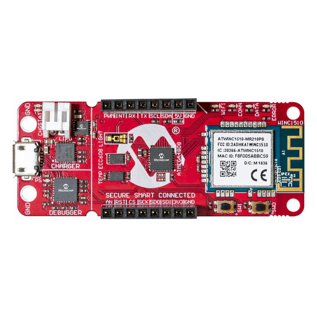
The AVR-IoT WA development board combines a powerful ATmega4808 AVR MCU, an ATECC608A CryptoAuthentication secure element IC and the fully certified ATWINC1510 Wi-Fi network controller – which provides the most simple and effective way to connect your embedded application to Amazon Web Services (AWS). The board also includes an on-board debugger, and requires no external hardware to program and debug the MCU.
Out of the box, the MCU comes preloaded with a firmware image that enables you to quickly connect and send data to the AWS platform using the on-board temperature and light sensors. Once you are ready to build your own custom design, you can easily generate code using the free software libraries in Atmel START or MPLAB Code Configurator (MCC).
The AVR-IoT WA board is supported by two award-winning Integrated Development Environments (IDEs) – Atmel Studio and Microchip MPLAB X IDE – giving you the freedom to innovate with your environment of choice.
Features
ATmega4808 microcontroller
Four user LED’s
Two mechanical buttons
mikroBUS header footprint
TEMT6000 Light sensor
MCP9808 Temperature sensor
ATECC608A CryptoAuthentication™ device
WINC1510 WiFi Module
On-board Debugger
Auto-ID for board identification in Atmel Studio and Microchip MPLAB X
One green board power and status LED
Programming and debugging
Virtual COM port (CDC)
Two DGI GPIO lines
USB and battery powered
Integrated Li-Ion/LiPo battery charger
The 555SE is an easy-to-build surface-mount soldering kit. It includes the circuit board, resistors, and transistors that make up the electrical circuit and printed assembly instructions. The kit also comes complete with the 'IC Leg' stand and 8 colour-coded thumbscrew terminal posts.
To build the 555SE, basic electronic soldering skill and tools are required, but no additional knowledge of electronics is presumed or required. You provide standard surface-mount soldering tools: a soldering iron, solder (wire or paste), small metal tweezers, as well as a Phillips head screwdriver.
The kit features relatively large surface mount components (1206 and SOT-23) and is a great first surface-mount soldering kit if you're just getting started. However, if you are experienced at surface mount soldering and have tools like a hot air rework station or other equipment, you're welcome to use them for assembling this kit.
Features
Anodized aluminium stand
8x 4-40 surface-mount threaded inserts
Stainless steel thumbscrews with colour-coded plastic caps (1 red, 1 black, 6 grey)
All materials (including the circuit board and stand) are RoHS compliant (lead-free)
Dimensions: 65 × 52 x 16 mm
Dimensions assembled: 65 × 78 × 20 mm
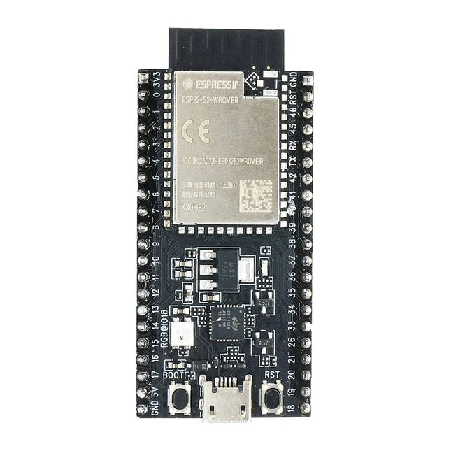
ESP32-S2-Saola-1R is a small-sized ESP32-S2 based development board. Most of the I/O pins are broken out to the pin headers on both sides for easy interfacing. Developers can either connect peripherals with jumper wires or mount ESP32-S2-Saola-1R on a breadboard.ESP32-S2-Saola-1R is equipped with the ESP32-S2-WROVER module, a powerful, generic Wi-Fi MCU module that has a rich set of peripherals. It is an ideal choice for a wide variety of application scenarios relating to Internet of Things (IoT), wearable electronics and smart home. The board a PCB antenna and features a 4 MB external SPI flash and an additional 2 MB SPI Pseudo static RAM (PSRAM).FeaturesMCU
ESP32-S2 embedded, Xtensa® single-core 32-bit LX7 microprocessor, up to 240 MHz
128 KB ROM
320 KB SRAM
16 KB SRAM in RTC
WiFi
802.11 b/g/n
Bit rate: 802.11n up to 150 Mbps
A-MPDU and A-MSDU aggregation
0.4 µs guard interval support
Center frequency range of operating channel: 2412 ~ 2484 MHz
Hardware
Interfaces: GPIO, SPI, LCD, UART, I²C, I²S, Camera interface, IR, pulse counter, LED PWM, TWAI (compatible with ISO 11898-1), USB OTG 1.1, ADC, DAC, touch sensor, temperature sensor
40 MHz crystal oscillator
4 MB SPI flash
Operating voltage/Power supply: 3.0 ~ 3.6 V
Operating temperature range: –40 ~ 85 °C
Dimensions: 18 × 31 × 3.3 mm
Applications
Generic Low-power IoT Sensor Hub
Generic Low-power IoT Data Loggers
Cameras for Video Streaming
Over-the-top (OTT) Devices
USB Devices
Speech Recognition
Image Recognition
Mesh Network
Home Automation
Smart Home Control Panel
Smart Building
Industrial Automation
Smart Agriculture
Audio Applications
Health Care Applications
Wi-Fi-enabled Toys
Wearable Electronics
Retail & Catering Applications
Smart POS Machines
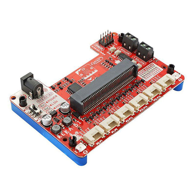
Program your REKA:BIT with Microsoft MakeCode Editor. Just add REKA:BIT MakeCode Extension and you’re good to go. If you’re a beginner, you can start with the block programming mode; simply drag, drop and snap the coding blocks together. For more advanced users, you can easily switch into JavaScript or Python mode on MakeCode Editor for text-based programming.
REKA:BIT possesses a lot of indicator LEDs to assist your coding and troubleshooting. It covers the IO pins connected to all six Grove ports and DC motor outputs from the co-processor. One is able to check his/her program and circuit connection easily by monitoring these LEDs.
Besides, REKA:BIT also has a power on/off indicator, undervoltage, and overvoltage LEDs built-in to give appropriate warnings should there be any problem with the power input.
REKA:BIT features a co-processor to handle multitasking more efficiently. Playing music while controlling up to 4x servo motors and 2x DC motors, animating micro:bit LED matrix, and even lighting up RGB LEDs in different colors, all at the same time, is not a problem for REKA:BIT.
Features
2x DC motor terminals
Built-in motor quick test buttons (no coding needed)
4x Servo motor ports
2x Neopixel RGB LEDs
6x Grove port (3.3 V)
3x Analog Input / Digital IO ports
2x Digital IO ports
1x I²C Interface
DC jack for power input (3.6-6 V DC)
ON/OFF switch
Power on indicator
Undervoltage (LOW) indicator & protection
Over-voltage (HIGH) indicator & protection
Dimensions: 10.4 x 72 x 15 mm
Included
1x REKA:BIT expansion board
1x USB power and data cable
1x 4xAA battery holder
1x Mini screwdriver
3x Grove to female header cable
2x Building block 1x9 lift arm
4x Building block friction pin
Please note: micro:bit board not included
This set includes all necessary tools to start soldering, plus two festive minikits to put your skills to the test.
The basic tools for soldering are a soldering iron (110 V AC version) and a support piece. We also included lead-free solder which is pretty easy to work with and its fumes are not harmful! Lastly, you’ll need some side cutters to trim the component’s leads.
The first minikit is the electronic candle, it has a warm yellow LED that mimics a real candle! This little solder kit only has 6 components to solder, which makes it the ideal starter kit.
Then it’s time to expand your skills with the original electronic Christmas tree kit. Solder more advanced components and a whopping 16 red LEDs.
Each kit is accompanied by an illustrated and comprehensive manual to make sure that anyone can master the art of soldering.
Features
Soldering iron and support (230 V AC version)
Lead-free solder
Side cutters
2 minikits
The Home Automation HAT uses only pluggable connectors. In addition, the latest release (V4.0 and up) has two new communication ports: 1-Wire and RS485. The card uses only 5 V power. On-board step-up power supply generates 12 V to power the 0-10 V analog outputs. A general purpose push-button, wired directly to a Raspberry Pi GPIO pin, can be used to shut down Raspberry Pi without a keyboard, or to force any output to a desired state. Ideal solution for your Raspberry Pi Home Automation projects. Read temperatures in up to 8 zones with analog inputs. Control your heating and cooling system with the 8 onboard relays. Use the 8 optically isolated digital inputs for your security system. Activate the hardware watchdog to monitor and power cycle the Raspberry Pi in case of software lockup. Control four-light systems with the four PWM open-drain outputs (you supply external power up to 24 V). Control four light dimmers using 0-10 V outputs. Compatibility The card is compatible with all Raspberry Pi versions from Zero to 4. It shares the I²C bus using only two of the Raspberry Pi’s GPIO pins to manage all eight cards. This feature leaves the remaining 24 GPIOs available for the user. Power Requirements The Home Automation card needs 5 V to operate and can be powered from Raspberry Pi or from its own pluggable connector. The onboard relay coils are also powered from the 5 V. An on-board 5V to 12V step-up power supply generates the voltage to drive the 0-10 V analog outputs. A local 3.3 V regulator powers the rest of the circuitry. The card needs 50 mA to operate with all relays off. Each relay needs up to 80 mA to turn on. Relays The 8 on-board relays have contacts brought out to heavy duty pluggable connectors, which make the card easy to use when multiple cards are stacked up. Relays are grouped in two sections of four relays each, with one common terminal and one N-O contact for each relay. Relays are rated 10 A/24 VDC and 250 VAC, but due to the board geometry limitation, the relays can switch only 3 A and 24 V, AC or DC. Status LEDs show when RELAYS are ON or OFF. Stacking Multiple Cards Up to eight Home Automation cards can be stacked on your Raspberry Pi. Each card is identified by jumpers you install to indicate the level in the stack. Cards can be installed in any order. The three position jumper on the upper right corner of the card selects the stack level. Features Eight relays with status LEDs and and N.O contacts Eight layer stackable Eight 12-bit A/D inputs, 250 Hz sample rate Four 13-bit DAC outputs (0-10 V dimmers) Four PWM 24 V/4 A open-drain outputs Eight optically isolated digital inputs Contact closure/Event counters up to 500 Hz Four Quadrature Encoder inputs 26 GPIOs from Raspberry Pi available 1-WIRE and RS485 communication ports Pluggable Connectors 26-16 AWG for all ports On-board hardware watchdog On-board resettable fuse Reverse power supply protection Brass stand-offs, screws and nuts included Hardware self-test with loop-back cable Open source hardware, schematics available 32-bit Processor running at 64 MHz Uses only I²C port (address 0x28..0x2f ), all GPIO pins available Specifications Power supply: Pluggable Connector, 5 V/3 A Power consumption: 50 mA (all relays off), 700 mA (all relays on) On board resettable fuse: 3 A Open Drain outputs: maximum 3 A, 24 V Relays 1,2,3,4,5,8: N-O contacts, 6 A/24 VAC or DC Relays 6,7: 3 A/24 VAC or DC Analog Inputs: Maximum input voltage: 3 V Input Impedance: 50 KΩ Resolution: 12 bits Sample rate: 250 samples/sec. DAC Outputs: Resistive load: Minimum 1 KΩ Accuracy: ±1% Opto-isolated Digital Inputs: Input Forward Current: Typical 5 mA, maximum 50 mA Input Series Resistor: 1K Input Reverse Voltage: 5 V Input Forward Voltage: 25 V @ 10 mA Isolation Resistance: Minimum 1012 Ω Included Home Automation stackable Card for Raspberry Pi with self-test Card Mounting hardware 4x M2.5x18 mm male-female brass standoffs 4x M2.5x5 mm brass screws 4x M2.5 brass nuts 2x Stack level Jumpers All required Connector Plugs Laminated Plastic Card showing IO Pinout Downloads User's Guide Open Source Hardware Schematic 2D CAD Drawing Command Line Python Libraries Node-RED Nodes Domoticz Plugin OpenPLC
The DiP-Pi PIoT is an Advanced Powered, WiFi connectivity System with sensors embedded interfaces that cover most of possible needs for IoT application based on Raspberry Pi Pico. It can supply the system with up to 1.5 A @ 4.8 V delivered from 6-18 VDC on various powering schemes like Cars, Industrial plant etc., additionally to original micro-USB of the Raspberry Pi Pico. It supports LiPo or Li-Ion Battery with Automatic Charger as also automatic switching from cable powering to battery powering or reverse (UPS functionality) when cable powering lost. Extended Powering Source (EPR) is protected with PPTC Resettable fuse, Reverse Polarity, as also ESD.
The DiP-Pi PIoT contains Raspberry Pi Pico embedded RESET button as also ON/OFF Slide Switch that is acting on all powering sources (USB, EPR or Battery). User can monitor (via Raspberry Pi Pico A/D pins) battery level and EPR Level with PICO’s A/D converters. Both A/D inputs are bridged with 0402 resistors (0 OHM) therefore if for any reason user needs to use those Pico pins for their own application can be easy removed. The charger is automatically charging connected battery (if used) but in addition user can switch charger ON/OFF if their application needs it.
DiP-Pi PIoT can be used for cable powered IoT systems, but also for pure Battery Powered System with ON/OFF. Each powering source status is indicated by separate informative LEDs (VBUS, VSYS, VEPR, CHGR, V3V3).
User can use any capacity of LiPo or Li-Ion type; however, must take care to use PCB protected batteries with max discharge current allowed of 2 A. The embedded battery charger is set to charge battery with 240 mA current. This current is set by resistor so if user need more/less can himself to change it. The DiP-Pi PIoT is also equipped with WiFi ESP8266 Clone module with embedded antenna. This feature open a wide range of IoT applications based on it.
In Addition to all above features DiP-Pi PIoT is equipped with embedded 1-wire, DHT11/22 sensors, and micro–SD Card interfaces. Combination of the extended powering, battery, and sensors interfaces make the DiP-Pi PIoT ideal for IoT applications like data logger, plants monitoring, refrigerators monitoring etc.
DiP-Pi PIoT is supported with plenty of ready to use examples written in Micro Python or C/C++.
Specifications
General
Dimensions 21 x 51 mm
Raspberry Pi Pico pinout compatible
Independent Informative LEDs (VBUS, VSYS, VEPR, CHGR, V3V3)
Raspberry Pi Pico RESET Button
ON/OFF Slide Switch acting on all powering sources (USB, EPR, Battery)
External Powering 6-18 VDC (Cars, Industrial Applications etc.)
External Power (6-18 VDC) Level Monitoring
Battery Level Monitoring
Inverse Polarity Protection
PPTC Fuse Protection
ESD Protection
Automatic Battery Charger (for PCB protected LiPo, Li-Ion – 2 A Max) Automatic/User Control
Automatic Switch from Cable Powering to Battery Powering and reverse (UPS Functionality)
Various powering schemes can be used at the same time with USB Powering, External Powering and Battery Powering
1.5 A @ 4.8 V Buck Converter on EPR
Embedded 3.3 V @ 600 mA LDO
ESP8266 Clone WiFi Connectivity
ESP8266 Firmware Upload Switch
Embedded 1-wire Interface
Embedded DHT-11/22 Interface
Powering Options
Raspberry Pi Pico micro-USB (via VBUS)
External Powering 6-18 V (via dedicated Socket – 3.4/1.3 mm)
External Battery
Supported Battery Types
LiPo with protection PCB max current 2A
Li-Ion with protection PCB max current 2A
Embedded Peripherals and Interfaces
Embedded 1-wire interface
Embedded DHT-11/22 Interface
Micro SD Card Socket
Programmer Interface
Standard Raspberry Pi Pico C/C++
Standard Raspberry Pi Pico Micro Python
Case Compatibility
DiP-Pi Plexi-Cut Case
System Monitoring
Battery Level via Raspberry Pi Pico ADC0 (GP26)
EPR Level via Raspberry Pi Pico ADC1 (GP27)
Informative LEDs
VB (VUSB)
VS (VSYS)
VE (VEPR)
CH (VCHR)
V3 (V3V3)
System Protection
Direct Raspberry Pi Pico Hardware Reset Button
ESD Protection on EPR
Reverse Polarity Protection on EPR
PPTC 500 mA @ 18 V fuse on EPR
EPR/LDO Over Temperature protection
EPR/LDO Over Current protection
System Design
Designed and Simulated with PDA Analyzer with one of the most advanced CAD/CAM Tools – Altium Designer
Industrial Originated
PCB Construction
2 ozcopper PCB manufactured for proper high current supply and cooling
6 mils track/6 mils gap technology 2 layers PCB
PCB Surface Finishing – Immersion Gold
Multi-layer Copper Thermal Pipes for increased System Thermal Response and better passive cooling
Downloads
Datasheet
Manual
Take control of and monitor your world with this ultimate jack-of-all-trades Raspberry Pi HAT!
This home monitoring and automation controller is packed with features to supercharge Raspberry Pi projects. With relays, analog channels, powered outputs, and buffered inputs (all 24 V tolerant), a wide range of devices and sensors can be connected simultaneously.
Each channel includes its own indicator LED for instant status feedback. Even the analog channels feature dimming LEDs that reflect live sensor values—smooth and practical.
Ideal for smart home and automation projects such as greenhouse irrigation, automated fish feeding, or customized scheduling.
Features
3x 24 V @ 2 A relays (NC and NO terminals)
3x 12-bit ADC @ 0-24 V (±2% accuracy)
3x 24 V tolerant buffered inputs
3x 24 V tolerant sinking outputs
15x channel indicator LEDs
1x 12-bit ADC @ 0-3.3 V
3.5 mm screw terminals
Power, Comms, and Warn! LED indicators
SPI, TX (#14), RX (#15), #25 pins broken out
Automation HAT pinout
Compatible with all 40-pin header Raspberry Pi models
Python library
Schematic
Comes fully assembled (broken out pins require soldering)
Software
As ever, we've made a super-simple to use Python library to take advantage of Automation HAT's multitudinous functions, with examples to get you started.
Our input, output and relay examples show you how to read the analog and digital inputs, switch the outputs on and off, and control the relays.
Notes
We recommend you use a set of brass M2.5 standoffs with Automation HAT to avoid pins contacting the HDMI port if the HAT is pushed down
Loads for the buffered outputs should be switched on the ground side, i.e. 12/24 V (from supply) -> load -> output terminal -> ground (from supply)
The relays can tolerate up to 2 A each and should be switched on the high side
The sinking outputs can sink a maximum 500 mA total across the 3 outputs, so if you use a single channel you can sink the whole 500 mA across it.
The accuracy of the ADC is ±2%.
Do not use to switch mains voltages!
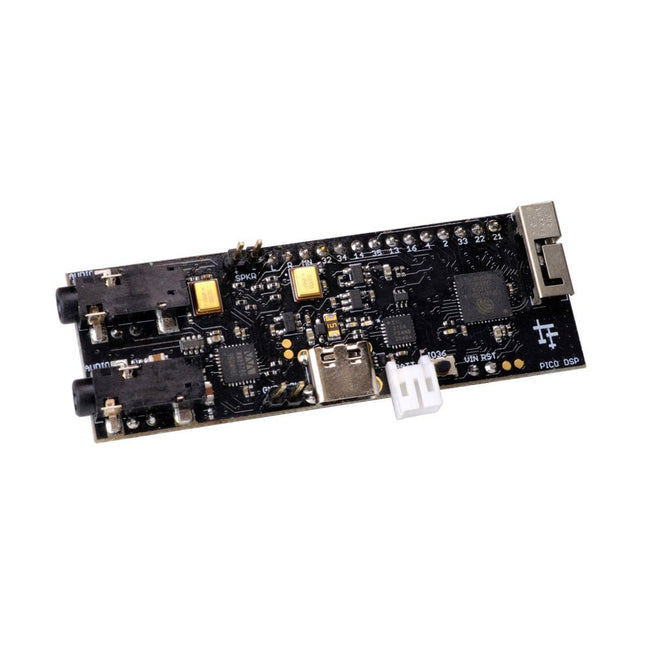
PÚCA DSP is an open-source, Arduino-compatible ESP32 development board for audio and digital signal processing (DSP) applications with expansive audio-processing features. It provides audio inputs, audio outputs, a low-noise microphone array, an integrated test-speaker option, additional memory, battery-charge management, and ESD protection all on a small, breadboard-friendly PCB.
Synthesizers, Installations, Voice UI, and More
PÚCA DSP can be used for a wide range of DSP applications, including but not limited to those in the fields of music, art, creative technology, and adaptive technology. Music-related examples include digital-music synthesis, mobile recording, Bluetooth speakers, wireless line-level directional microphones, and the design of smart musical instruments. Art-related examples include acoustic sensor networks, sound-art installations, and Internet-radio applications. Examples related to creative and adaptive technology include voice user interface (VUI) design and Web audio for the Internet of Sounds.
Compact, Integrated Design
PÚCA DSP was designed for portability. When used with an external 3.7 V rechargeable battery, it can be deployed almost anywhere or integrated into just about any device, instrument, or installation. Its design emerged from months of experimentation with various ESP32 development boards, DAC breakout boards, ADC breakout boards, Microphone breakout boards, and audio-connector breakout boards, and – despite its diminutive size – it manages to provide all of that functionality in a single board. And it dos so without compromising signal quality.
Specifications
Processor & Memory
Espressif ESP32 Pico D4 Processor
32-bit dual core 80 MHz / 160 MHz / 240 MHz
4 MB SPI Flash with 8 MB additional PSRAM (Original Edition)
Wireless 2.4 GHz Wi-Fi 802.11b/g/n
Bluetooth BLE 4.2
3D Antenna
Audio
Wolfson WM8978 Stereo Audio Codec
Audio Line In on 3.5 mm stereo onnector
Audio Headphone / Line Out on 3.5 mm stereo connector
Stereo Aux Line In, Audio Mono Out routed to GPIO Header
2x Knowles SPM0687LR5H-1 MEMS Microphones
ESD protection on all audio inputs and outputs
Support for 8, 11.025, 12, 16, 22.05, 24, 32, 44.1 and 48 kHz sample rates
1 W Speaker Driver, routed to GPIO Header
DAC SNR 98 dB, THD -84 dB (‘A’ weighted @ 48 kHz)
ADC SNR 95 dB, THD -84 dB (‘A’ weighted @ 48 kHz)
Line input impedance: 1 MOhm
Line output impedance: 33 Ohm
Form Factor and Connectivity
Breadboard friendly
70 x 24 mm
11x GPIO pins broken out to 2.54 mm pitch header, with access to both ESP32 ADC channels, JTAG and capacitive touch pins
USB 2.0 over USB Type C connector
Power
3.7/4.2 V Lithium Polymer Rechargeable Battery, USB or external 5 V DC power source
ESP32 and Audio Codec can be placed into low power modes under software control
Battery voltage level detection
ESD protection on USB data bus
Downloads
GitHub
Datasheet
Links
Crowd Supply Campaign (includes FAQs)
Hardware Overview
Programming the Board
The Audio Codec
This QWIIC connector allows you to easily connect QWIIC enabled modules to a Raspberry Pi, without the need for soldering. It uses a 2x3 pin female header which sits on top of the first 6 GPIO pins and breaks out the 3.3v, GND and the two I²C pins (SDA, SCL) on a 4 pin JST connector which sits on top.
This programmer is specifically designed for burning bootloaders (without a computer) on Arduino-compatible ATmega328P/ATmega328PB development boards.
Simply plug the programmer into the ICSP interface to re-burn the bootloader. It’s also compatible with new chips, provided the IC is functional.
Note: Burning a bootloader erases all previous chip data.
Features
Working voltage: 3.1-5.3 V
Working current: 10 mA
Compatible with Arduino Uno R3 based boards (ATmega328P or ATmega328PB)
Dimensions: 39.6 x 15.5 x 7.8 mm