Physical Products
-
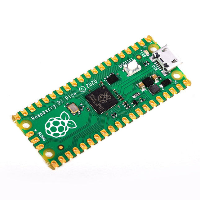
Raspberry Pi Foundation Raspberry Pi Pico
Specifications RP2040 microcontroller chip designed by Raspberry Pi in the UK Dual-core ARM Cortex M0+ processor, with a flexible clock running up to 133 MHz 264 kB SRAM, and 2 MB on-board Flash memory Castellated module allows soldering directly to carrier boards USB 1.1 host and device support Energy-efficient sleep and dormant modes Drag and drop programming using mass storage via USB 26x multifunction GPIO pins 2x SPI, 2x I²C, 2x UART, 3x 12-bit ADC, 16x controllable PWM channels On-chip accurate clock and timer Temperature sensor On-chip accelerated floating point libraries 8x programmable IO (PIO) state machines for custom peripherals Why a Raspberry Pi Pico? Designing your own microcontroller instead of buying an existing one brings a number of advantages. According to Raspberry Pi itself, not one of the existing products available for this comes close to their price/performance ratio. This Raspberry Pi Pico has also given Raspberry Pi the ability to add some innovative and powerful features of their own. These features are not available anywhere else. A third reason is that the Raspberry Pi Pico has given Raspberry Pi the ability to create powerful software around the product. Surrounding this software stack is an extensive documentation set. The software and documentation meet the high standard of Raspberry Pi's core products (such as the Raspberry Pi 400, Pi 4 Model B and Pi 3 Model A+). Who is this microcontroller for? The Raspberry Pi Pico is suitable for both advanced and novice users. From controlling a display to controlling many different devices that you use every day. Automating everyday operations is made possible by this technology. Beginner users The Raspberry Pi Pico is programmable in the C and MicroPython languages and is customizable for a wide range of devices. In addition, the Pico is as easy to use as dragging and dropping files. This makes this microcontroller ideally suited for the novice user. Advanced users For advanced users, it is possible to take advantage of the Pico's extensive peripherals. The peripherals include the SPI, I²C, and eight programmable I/O (PIO)-state machines. What makes the Raspberry Pi Pico unique? What's unique about the Pico is that it was developed by Raspberry Pi itself. The RP2040 features a dual-core Arm Cortex-M0+ processor with 264 KB of internal RAM and support for up to 16 MB of off-chip Flash. The Raspberry Pi Pico is unique for several reasons: The product has the highest price/quality ratio in the microcontroller board market. The Raspberry Pi Pico has been developed by Raspberry Pi itself. The software stack surrounding this product is of high quality and comes paired with a comprehensive documentation set.
-
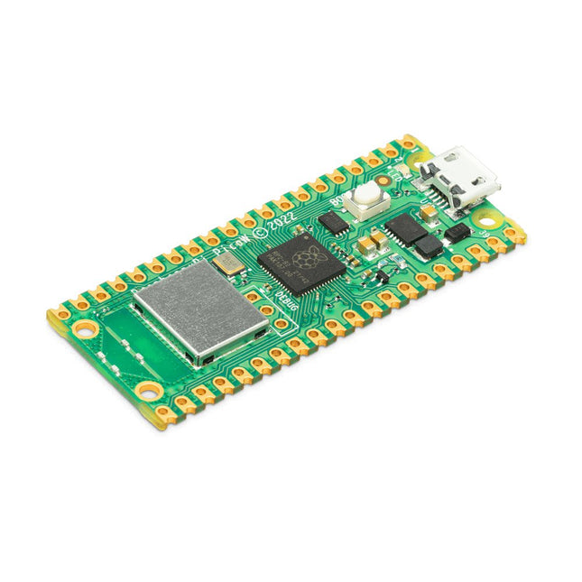
Raspberry Pi Foundation Raspberry Pi Pico W
Raspberry Pi Pico W is a microcontroller board based on the Raspberry Pi RP2040 microcontroller chip. The RP2040 microcontroller chip ('Raspberry Silicon') offers a dual-core ARM Cortex-M0+ processor (133 MHz), 256 KB RAM, 30 GPIO pins, and many other interface options. In addition, there is 2 MB of on-board QSPI flash memory for code and data storage. Raspberry Pi Pico W has been designed to be a low cost yet flexible development platform for RP2040 with a 2.4 GHz wireless interface using an Infineon CYW43439. The wireless interface is connected via SPI to the RP2040. Features of Pico W RP2040 microcontroller with 2 MB of flash memory On-board single-band 2.4 GHz wireless interfaces (802.11n) Micro USB B port for power and data (and for reprogramming the flash) 40 pin 21 x 51 mm 'DIP' style 1 mm thick PCB with 0.1' through-hole pins also with edge castellations Exposes 26 multi-function 3.3 V general purpose I/O (GPIO) 23 GPIO are digital-only, with three also being ADC capable Can be surface mounted as a module 3-pin ARM serial wire debug (SWD) port Simple yet highly flexible power supply architecture Various options for easily powering the unit from micro USB, external supplies or batteries High quality, low cost, high availability Comprehensive SDK, software examples and documentation Features of the RP2040 microcontroller Dual-core cortex M0+ at up to 133 MHz On-chip PLL allows variable core frequency 264 kByte multi-bank high performance SRAM External Quad-SPI Flash with eXecute In Place (XIP) and 16 kByte on-chip cache High performance full-crossbar bus fabric On-board USB1.1 (device or host) 30 multi-function general purpose I/O (four can be used for ADC) 1.8-3.3 V I/O voltage 12-bit 500 ksps analogue to digital converter (ADC) Various digital peripherals 2x UART, 2x I²C, 2x SPI, 16x PWM channels 1x timer with 4 alarms, 1x real time clock 2x programmable I/O (PIO) blocks, 8 state machines in total Flexible, user-programmable high-speed I/O Can emulate interfaces such as SD card and VGA Note: Raspberry Pi Pico W I/O voltage is fixed at 3.3 V. Downloads Datasheet Specifications of 3-pin Debug Connector
-
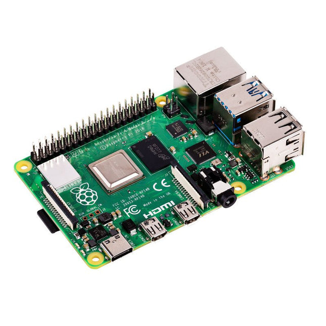
Raspberry Pi Foundation Raspberry Pi 4 B (4 GB RAM)
The Raspberry Pi 4 B is 3x faster than its 3 B+ predecessor and offers 4x faster multimedia performance (comparable to the desktop performance of an entry-level x86-based PC). Features High-performance 64-bit quad-core processor Dual-display support at resolutions up to 4K via a pair of micro-HDMI ports Hardware video decode at up to 4Kp60 Up to 8 GB of RAM Dual-band 2.4/5 GHz wireless LAN Bluetooth 5.0 Gigabit Ethernet USB 3.0 PoE capability (via a separate PoE HAT add-on) Specifications SoC Broadcom BCM2711 CPU 64-bit ARM Cortex-A72 (4x 1.5 GHz) GPU Broadcom VideoCore VI RAM Up to 8 GB LPDDR4 Wireless LAN 2.4 GHz and 5 GHz IEEE 802.11b/g/n/ac wireless LAN Bluetooth Bluetooth 5.0, BLE Ethernet Gigabit Ethernet USB 2x USB-A 3.02x USB-A 2.0 GPIO Standard 40-pin GPIO header (fully backwards-compatible with previous boards) Video 2x micro-HDMI ports (up to 4Kp60 supported)2-lane MIPI DSI port (display)2-lane MIPI CSI port (camera) Audio 4-pole stereo audio and composite video port Multimedia H.265 (4Kp60 decode)H.264 (1080p60 decode, 1080p30 encode)OpenGL ES, 3.0 graphics SD card microSD (for operating system and storage) Power 5 V | 3 A (via USB-C)5 V | 3 A (via GPIO)Power over Ethernet (PoE) enabled – (requires separate PoE HAT) Raspberry Pi 4 B 1 GB RAM 2 GB RAM 8 GB RAM
-
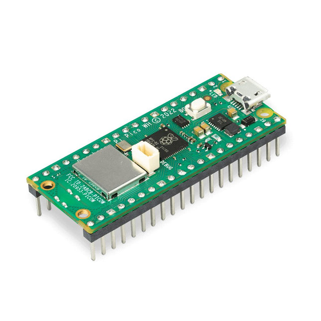
Raspberry Pi Foundation Raspberry Pi Pico WH
Raspberry Pi Pico WH is a microcontroller board based on the Raspberry Pi RP2040 microcontroller chip. The RP2040 microcontroller chip ('Raspberry Silicon') offers a dual-core ARM Cortex-M0+ processor (133 MHz), 256 KB RAM, 30 GPIO pins, and many other interface options. In addition, there is 2 MB of on-board QSPI flash memory for code and data storage. Raspberry Pi Pico WH has been designed to be a low cost yet flexible development platform for RP2040 with a 2.4 GHz wireless interface using an Infineon CYW43439. The wireless interface is connected via SPI to the RP2040. Features of Pico WH RP2040 microcontroller with 2 MB of flash memory On-board single-band 2.4 GHz wireless interfaces (802.11n) Micro USB B port for power and data (and for reprogramming the flash) 40 pin 21 x 51 mm 'DIP' style 1 mm thick PCB with 0.1' through-hole pins also with edge castellations Exposes 26 multi-function 3.3 V general purpose I/O (GPIO) 23 GPIO are digital-only, with three also being ADC capable Can be surface mounted as a module 3-pin ARM serial wire debug (SWD) port Simple yet highly flexible power supply architecture Various options for easily powering the unit from micro USB, external supplies or batteries High quality, low cost, high availability Comprehensive SDK, software examples and documentation Pre-populated headers and 3-pin debug connector Features of the RP2040 microcontroller Dual-core cortex M0+ at up to 133 MHz On-chip PLL allows variable core frequency 264 kByte multi-bank high performance SRAM External Quad-SPI Flash with eXecute In Place (XIP) and 16 kByte on-chip cache High performance full-crossbar bus fabric On-board USB1.1 (device or host) 30 multi-function general purpose I/O (four can be used for ADC) 1.8-3.3 V I/O voltage 12-bit 500 ksps analogue to digital converter (ADC) Various digital peripherals 2x UART, 2x I²C, 2x SPI, 16x PWM channels 1x timer with 4 alarms, 1x real time clock 2x programmable I/O (PIO) blocks, 8 state machines in total Flexible, user-programmable high-speed I/O Can emulate interfaces such as SD card and VGA Note: Raspberry Pi Pico W I/O voltage is fixed at 3.3 V. Downloads Datasheet Specifications of 3-pin Debug Connector
-
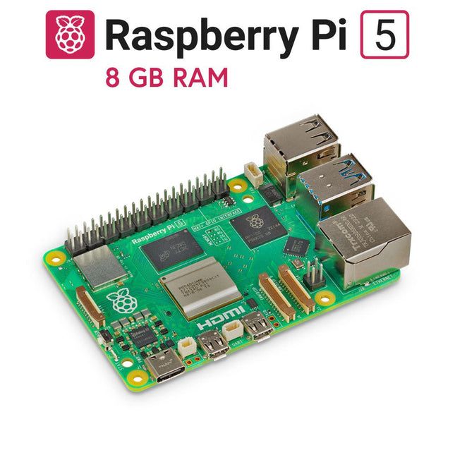
Raspberry Pi Foundation Raspberry Pi 5 (8 GB RAM)
The Raspberry Pi 5 delivers more performance than ever before. Thanks to the faster CPU, GPU and RAM, Raspberry Pi 5 is up to 3x faster than its already fast predecessor. In addition to the speed boost, the Raspberry Pi 5 (which features the new Raspberry Pi RP1 silicon for advanced I/O capabilities) also offers the following features for the first time ever: RTC, an on/off button and a PCIe interface. Features 64-bit quad-core ARM Cortex-A76 processor (2.4 GHz) VideoCore VII GPU (800 MHz) 8 GB of LPDDR4X RAM (4267 MHz) Raspberry Pi silicon RP1 I/O controller chip Real-time clock On/off button PCIe 2.0 UART connector Fan connector Specifications SoC Broadcom BCM2712 CPU ARM Cortex-A76 (ARM v8) 64-bit Clock speed 4x 2.4 GHz GPU VideoCore VII (800 MHz) RAM 8 GB LPDDR4X (4267 MHz) WiFi IEEE 802.11b/g/n/ac (2.4 GHz/5 GHz) Bluetooth Bluetooth 5.0, BLE Ethernet Gigabit Ethernet (with PoE+ support) USB 2x USB-A 3.0 (5 GBit/s)2x USB-A 2.0 PCI Express 1x PCIe 2.0 GPIO Standard 40-pin GPIO header Video 2x micro-HDMI ports (4K60)2x 4-lane MIPI (DSI/CSI) Multimedia H.265 (4K60 decode)OpenGL ES 3.1, Vulkan 1.2 SD card microSD Power 5 V/5 A (via USB-C)Power over Ethernet (PoE+) Raspberry Pi 4 vs Raspberry Pi 5 Raspberry Pi 4 Raspberry Pi 5 SoC Broadcom BCM2711 Broadcom BCM2712 CPU ARM Cortex-A72 (ARM v8) 64-bit ARM Cortex-A76 (ARM v8) 64-bit Clock speed 4x 1.5 GHz 4x 2.4 GHz L2 cache 1 MByte shared 4x 512 KByte L3 cache N/A 2 MByte shared GPU VideoCore VI (500 MHz) VideoCore VII (800 MHz) RAM 8 GB LPDDR4 (3200 MHz) 8 GB LPDDR4X (4267 MHz) WiFi IEEE 802.11b/g/n/ac (2.4 GHz/5 GHz) IEEE 802.11b/g/n/ac (2.4 GHz/5 GHz) Bluetooth Bluetooth 5.0, BLE Bluetooth 5.0, BLE Ethernet Gigabit Ethernet (with PoE support) Gigabit Ethernet (with PoE+ support) USB 2x USB-A 3.02x USB-A 2.0 2x USB-A 3.0 (5 GBit/s)2x USB-A 2.0 I/O controller chip N/A Raspberry Pi Silicon RP1 PCI Express N/A 1x PCIe 2.0 Real Time Clock (RTC) N/A RTC and RTC battery connector On/off button N/A Onboard power button Cooling N/A Fan connector GPIO Standard 40-pin GPIO header Standard 40-pin GPIO header UART via GPIO 1x UART connector SD card microSD slot (DDR50) microSD slot (SDR104) Video 2x micro-HDMI ports (4K60)1x 2-lane MIPI DSI port (display)1x 2-lane MIPI CSI port (camera) 2x micro-HDMI ports (4K60)2x 4-lane MIPI (DSI/CSI) Audio 4-pole 3.5 mm audio jack (stereo audio and composite video) N/A Multimedia H.265 (4K60 decode)H.264 (1080p60 decode, 1080p30 encode)OpenGL ES, 3.0 graphics H.265 (4K60 decode)OpenGL ES 3.1, Vulkan 1.2 Power 5 V/3 A (15 W)Power over Ethernet (PoE) 5 V/5 A (25 W), USB PDPower over Ethernet (PoE+) Raspberry Pi 5 2 GB RAM 4 GB RAM 16 GB RAM Downloads Datasheet Unboxing the Raspberry Pi 5 First Insights
-

RTL-SDR RTL-SDR V3 (incl. Dipole Antenna Kit)
RTL-SDR is an affordable dongle that can be used as a computer based radio scanner for receiving live radio signals in your area. This particular dongle includes a R820T2 tuner, a 1 PPM temperature compensated oscillator (TCXO), SMA F connector. It features an aluminium case with passive cooling via a thermal pad. Moreover, there is a software switchable bias tee circuit, supplementary ESD protection, lower overall noise and built-in direct sampling for HF reception. This device can receive frequencies from 500 kHz to 1.7 GHz and has up to 3.2 MHz of instantaneous bandwidth (2.4 MHz stable). Note: RTL-SDR dongles are RX only. You can use this kit either for terrestrial or satellite reception just by changing the orientation of the antenna. Thanks to the included mounts and extension cables it is possible to temporarily place the antenna outside for a better reception. Other potential applications are general radio scanning, air traffic control, public safety radio, ADSB, ACARS, trunked radio, P25 digital voice, POCSAG, weather balloons, APRS, NOAA APT weather satellites, radio astronomy, meteor scatter monitoring etc. Included RTL-SDR V3 Dongle (R820T2 RTL2832U 1PPM TCXO SMA) 2x 23 cm to 1 m telescopic antenna 2x 5 cm to 13 cm telescopic antenna Dipole Antenna Base with 60 cm RG174 extension cable 3 m RG174 extension cable Flexible Tripod Mount Suction Cup Mount Downloads Datasheet Quick Start Guide SDR# User Guide Dipole Antenna Kit Guide
-
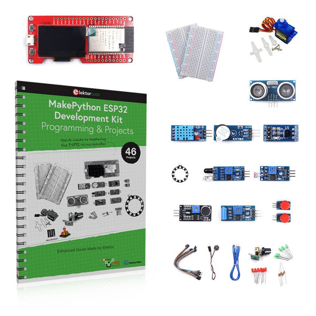
Elektor Bundles MakePython ESP32 Development Kit (EN)
Learn how to use the ESP32 Microcontroller and MicroPython programming in your future projects! The project book, written by well-known Elektor author Dogan Ibrahim, holds many software- and hardware-based projects especially developed for the MakePython ESP32 Development Kit. The kit comes with several LEDs, sensors, and actuators. The kit will help you acquire the basic knowledge to create IoT projects. The book’s fully evaluated projects feature all the supplied components. Each project includes a block diagram, a circuit diagram, a full program listing, and a complete program description. Included in the kit 1x MakePython ESP32 development board with LCD 1x Ultrasonic ranging module 1x Temperature and humidity sensor 1x Buzzer module 1x DS18B20 module 1x Infrared module 1x Potentiometer 1x WS2812 module 1x Sound sensor 1x Vibration sensor 1x Photosensitive resistance module 1x Pulse sensor 1x Servo motor 1x USB cable 2x Button 2x Breadboard 45x Jumper wire 10x Resistor 330R 10x LED (Red) 10x LED (Green) 1x Project book (206 pages) 46 Projects in the Book LED Projects Blinking LED Flashing SOS Blinking LED – using a timer Alternately flashing LEDs Button control Changing the LED flashing rate using pushbutton interrupts Chasing-LEDs Binary-counting LEDs Christmas lights (random-flashing 8 LEDs) Electronic dice Lucky day of the week Pulsewidth Modulation (PWM) Projects Generate a 1000-Hz PWM waveform with 50% duty cycle LED brightness control Measuring the frequency and duty cycle of a PWM waveform Melody maker Simple electronic organ Servo motor control Servo motor DS18B20 thermometer Analog To Digital Converter (ADC) Projects Voltmeter Plotting the analog input voltage ESP32 internal temperature sensor Ohmmeter Photosensitive resistance module Digital To Analog Converter (DAC) Projects Generating fixed voltages Generating a sawtooth-wave signal Generating a triangular-wave signal Arbitrary periodic waveform Generating a sinewave signal Generating accurate sinewave signal using timer interrupts Using The OLED Display Seconds counter Event counter DS18B20 OLED based digital thermometer ON-OFF temperature controller Measuring the temperature and humidity Ultrasonic distance measurement Height of a person (stadiometer) Heart rate (pulse) measurement Other Sensors Supplied with the Kit Theft alarm Sound-activated light Infrared obstacle avoidance with buzzer WS2812 RGB LED ring Timestamping temperature and humidity readings Network Programming Wi-Fi scanner Remote control from the Internet browser (using a smartphone or PC) – Web Server Storing temperature and humidity data in the Cloud Low-Power Operation Using a timer to wake up the processor
€ 89,95€ 69,95
Best Price
-
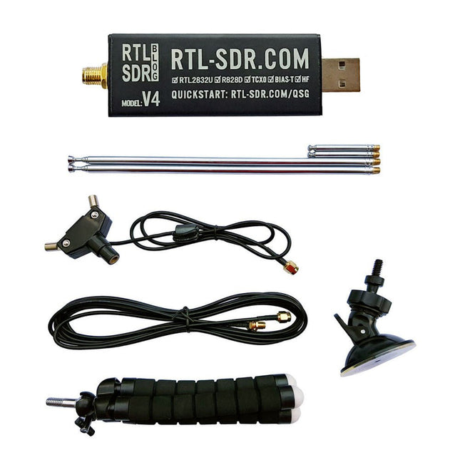
RTL-SDR RTL-SDR V4 (incl. Dipole Antenna Kit)
RTL-SDR is an affordable dongle that can be used as a computer-based radio scanner for receiving live radio signals between 500 kHz and 1.75 GHz in your area. The RTL-SDR V4 offers several improvements over generic brands including use of the R828D tuner chip, triplexed input filter, notch filter, improved component tolerances, a 1 PPM temperature compensated oscillator (TCXO), SMA F connector, aluminium case with passive cooling, bias tee circuit, improved power supply, and a built in HF upconverter. RTL-SDR V4 comes with the portable dipole antenna kit. It is great for beginners as it allows for terrestrial and satellite reception and easy to mount outdoors and designed for portable and temporary outside usage. Features Improved HF reception: V4 now uses a built-in upconverter instead of using a direct sampling circuit. This means no more Nyquist folding of signals around 14.4 MHz, improved sensitivity, and adjustable gain on HF. Like the V3, the lower tuning range remains at 500 kHz and very strong reception may still require front end attenuation/filtering. Improved filtering: The V4 makes use of the R828D tuner chip, which has three inputs. The SMA input has been triplexed input into 3 bands: HF, VHF and UHF. This provides some isolation between the 3 bands, meaning out of band interference from strong broadcast stations is less likely to cause desensitization or imaging. Improved filtering x2: In addition to the triplexing, the open drain pin on the R828D can be also used, which allows to add simple notch filters for common interference bands such as broadcast AM, broadcast FM and the DAB bands. These only attenuate by a few dB, but may still help. Improved phase noise on strong signals: Due to an improved power supply design, phase noise from power supply noise has been significantly reduced. Less heat: Another advantage of the improved power supply is low power consumption and less heat generation compared to the V3. Included 1x RTL-SDR V4 dongle (R828D RTL2832U 1PPM TCXO SMA) 2x 23 cm to 1 m telescopic antenna 2x 5 cm to 13 cm telescopic antenna 1x Dipole antenna base with 60 cm RG174 1x 3 m RG174 extension cable 1x Flexible tripod mount 1x Suction cup mount Downloads Datasheet User Guide Quick Start Guide SDR# User Guide Dipole Antenna Guide
€ 74,95
Members: € 67,46
-

Raspberry Pi Foundation Raspberry Pi 4 B (8 GB RAM)
The Raspberry Pi 4 B is 3x faster than its 3 B+ predecessor and offers 4x faster multimedia performance (comparable to the desktop performance of an entry-level x86-based PC). Features High-performance 64-bit quad-core processor Dual-display support at resolutions up to 4K via a pair of micro-HDMI ports Hardware video decode at up to 4Kp60 Up to 8 GB of RAM Dual-band 2.4/5 GHz wireless LAN Bluetooth 5.0 Gigabit Ethernet USB 3.0 PoE capability (via a separate PoE HAT add-on) Specifications SoC Broadcom BCM2711 CPU 64-bit ARM Cortex-A72 (4x 1.5 GHz) GPU Broadcom VideoCore VI RAM Up to 8 GB LPDDR4 Wireless LAN 2.4 GHz and 5 GHz IEEE 802.11b/g/n/ac wireless LAN Bluetooth Bluetooth 5.0, BLE Ethernet Gigabit Ethernet USB 2x USB-A 3.02x USB-A 2.0 GPIO Standard 40-pin GPIO header (fully backwards-compatible with previous boards) Video 2x micro-HDMI ports (up to 4Kp60 supported)2-lane MIPI DSI port (display)2-lane MIPI CSI port (camera) Audio 4-pole stereo audio and composite video port Multimedia H.265 (4Kp60 decode)H.264 (1080p60 decode, 1080p30 encode)OpenGL ES, 3.0 graphics SD card microSD (for operating system and storage) Power 5 V | 3 A (via USB-C)5 V | 3 A (via GPIO)Power over Ethernet (PoE) enabled – (requires separate PoE HAT) Raspberry Pi 4 B 1 GB RAM 2 GB RAM 4 GB RAM
-
Elektor Publishing PID-based Practical Digital Control with Raspberry Pi and Arduino Uno
The Arduino Uno is an open-source microcontroller development system encompassing hardware, an Integrated Development Environment (IDE), and a vast number of libraries. It is supported by an enormous community of programmers, electronic engineers, enthusiasts, and academics. The libraries in particular really smooth Arduino programming and reduce programming time. What’s more, the libraries greatly facilitate testing your programs since most come fully tested and working. The Raspberry Pi 4 can be used in many applications such as audio and video media devices. It also works in industrial controllers, robotics, games, and in many domestic and commercial applications. The Raspberry Pi 4 also offers Wi-Fi and Bluetooth capability which makes it great for remote and Internet-based control and monitoring applications. This book is about using both the Raspberry Pi 4 and the Arduino Uno in PID-based automatic control applications. The book starts with basic theory of the control systems and feedback control. Working and tested projects are given for controlling real-life systems using PID controllers. The open-loop step time response, tuning the PID parameters, and the closed-loop time response of the developed systems are discussed together with the block diagrams, circuit diagrams, PID controller algorithms, and the full program listings for both the Raspberry Pi and the Arduino Uno. The projects given in the book aim to teach the theory and applications of PID controllers and can be modified easily as desired for other applications. The projects given for the Raspberry Pi 4 should work with all other models of Raspberry Pi family. The book covers the following topics: Open-loop and closed-loop control systems Analog and digital sensors Transfer functions and continuous-time systems First-order and second-order system time responses Discrete-time digital systems Continuous-time PID controllers Discrete-time PID controllers ON-OFF temperature control with Raspberry Pi and Arduino Uno PID-based temperature control with Raspberry Pi and Arduino Uno PID-based DC motor control with Raspberry Pi and Arduino Uno PID-based water level control with Raspberry Pi and Arduino Uno PID-based LED-LDR brightness control with Raspberry Pi and Arduino Uno
€ 39,95
Members: € 35,96
-

LabNation LabNation SmartScope USB Oscilloscope
SmartScope is a compact 2-channel USB oscilloscope with a bandwidth of 30 MHz and a sampling rate of 2x 100 MSa/s. It is compatible with all major platforms, including Windows, macOS, Linux, and Android. The operation and display of measurement signals are done via smartphone, tablet, or PC. Additionally, a logic analyzer and a signal generator are integrated. Even more, you can get mobile with it: take the SmartScope on the road, thanks to the single-cable connectivity. Everything is going to be intuitive: pointing, pinching and swiping finally replaces the clunky interfaces of old scopes. With the SmartScope you develop your digital interfaces using the 100 MS/s logic analyzer. With this tool you can design any signal you want using Excel, then upload it to the built-in Arbitrary Waveform Generator (AWG). At the end capture the voltage at any point of your design at 100 million times each second. The Software for the support of Windows / macOS / Linux / Android and Export formats (Excel .csv / Matlab .mat) are given. Features Channel sampled at 100 MHz/s each AC/DC coupling on analog inputs 100% silent 64 Mbit RAM: x10000 zoom Arbitrary Waveform Generator 8 digital inputs at 100 MS/s each 4 digital outputs at 100 MS/s each Externally power your scope in case your mobile can't supply the juice. Specifications Oscilloscope Bandwidth 30 MHz (-3 dB point) Sample rate 2x 100 MS/s Channels 2 Max pre-trigger position 16x full scale Max post-trigger position Full scale Max full voltage scale 10 V/div (±35 V input range) Min full voltage scale 20 mV/div Analog input range -35 V, +35 V Max input peak-to-peak 40 V Signal coupling AC / DC Precision 8 bit Input impedance 1 MΩ // 10 pF Waverforms 200 waveforms/s Data delay to host < 10 ms Sample depth Up to 4 million samples per channel External trigger Yes Logic Analyzer Input channels 8 Input impedance 100 kOhm // 2 pF to GND Sample rate 100 MS/s Logic level 1.8 V to 5.0 V Diode protection Bidirectional Input data buffer 4 million samples Waverforms 200 waveforms/s Data delay to host < 10 ms Protocol decoders I²C, SPI, UART, I²S integrated User extensible Wave Generator (Analog Output) Output channels 1 Data rate Up to 50 MS/s Output level 0-3.3 V (Opamp driven) Output buffer Up to 2048 samples Max slew rate 30 ns/V Step 13 mV Wave Generator (Digital Output) Channels 4 Data rate Up to 100 MS/s Output level 3.3 V or 5 V (selectable) Output buffer Up to 2048 samples Diode protected Yes Programmable Logic USB controller MicroChip PIC18F14K50 USB interface PicKit3 or USB flashable FPGA Xilinx Spartan 6 FPGA interface JTAG and USB flashable Size & Weight Dimensions (L x W x D) 110 x 64 x 24.2 mm (4.33 x 2.52 x 0.95") Weight 158 g Case Aluminium Connectivity Device/Host mini USB included Record waveforms Store Matlab (.mat) or Excel (.csv) files through Dropbox Analog BNC 2 probes included Digital 8x 0.1" pitch, probes (included) Sync USB micro B-B Power USB micro B (optional) Included 1x SmartScope USB Oscilloscope 2x Analog probes 1x Digital probe cable 1x USB cable Downloads Software GitHub Wiki
-

Raspberry Pi Foundation Raspberry Pi 4 B (2 GB RAM)
The Raspberry Pi 4 B is 3x faster than its 3 B+ predecessor and offers 4x faster multimedia performance (comparable to the desktop performance of an entry-level x86-based PC). Features High-performance 64-bit quad-core processor Dual-display support at resolutions up to 4K via a pair of micro-HDMI ports Hardware video decode at up to 4Kp60 Up to 8 GB of RAM Dual-band 2.4/5 GHz wireless LAN Bluetooth 5.0 Gigabit Ethernet USB 3.0 PoE capability (via a separate PoE HAT add-on) Specifications SoC Broadcom BCM2711 CPU 64-bit ARM Cortex-A72 (4x 1.5 GHz) GPU Broadcom VideoCore VI RAM Up to 8 GB LPDDR4 Wireless LAN 2.4 GHz and 5 GHz IEEE 802.11b/g/n/ac wireless LAN Bluetooth Bluetooth 5.0, BLE Ethernet Gigabit Ethernet USB 2x USB-A 3.02x USB-A 2.0 GPIO Standard 40-pin GPIO header (fully backwards-compatible with previous boards) Video 2x micro-HDMI ports (up to 4Kp60 supported)2-lane MIPI DSI port (display)2-lane MIPI CSI port (camera) Audio 4-pole stereo audio and composite video port Multimedia H.265 (4Kp60 decode)H.264 (1080p60 decode, 1080p30 encode)OpenGL ES, 3.0 graphics SD card microSD (for operating system and storage) Power 5 V | 3 A (via USB-C)5 V | 3 A (via GPIO)Power over Ethernet (PoE) enabled – (requires separate PoE HAT) Raspberry Pi 4 B 1 GB RAM 4 GB RAM 8 GB RAM
-
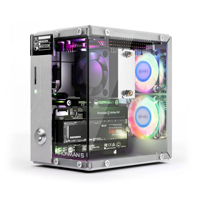
SunFounder Pironman 5 NVMe M.2 SSD PCIe Mini PC Case for Raspberry Pi 5
Enhance your Raspberry Pi 5 with the Pironman 5, built with sturdy aluminum, superior cooling, NVMe M.2 SSD support, OLED display, RGB lighting, standard HDMI ports x2, and a secure power switch. It is perfect for NAS, Home Assistant, Media and Game Centers. The Pironman 5 is not just a case; it’s an upgrade that transforms your Raspberry Pi 5 into a powerful, efficient, and stylish device. The Pironman 5 includes the Pi 5 NVMe PIP (PCIe Peripheral Board), a PCIe adapter board specifically designed for NVMe solid-state drives. This board supports four sizes of NVMe SSDs: 2230, 2242, 2260, and 2280, all of which can be installed in an M.2 M key slot. The connection is certified for Gen 2.0 speeds (5 GT/sec), but can be forced to Gen 3.0 (10 GT/sec) for faster performance. Expandable NVMe M.2 SSD Slot Boost your Raspberry Pi 5's performance with the Pironman 5's NVMe M.2 SSD slot, supporting multiple sizes (2230, 2242, 2260, 2280) for increased storage and faster system response. Advanced Cooling System Keep your Raspberry Pi 5 cool and stylish with the Pironman 5's tower cooler and dual RGB fans, featuring dust filters for durable, low-maintenance operation. OLED Display for Instant Insights The Pironman 5 includes a 0.96" OLED display, providing immediate updates on CPU and RAM usage, temperature, IP address, and more. Enhanced Functionality and Safety The Pironman 5 secures your Raspberry Pi 5 with features like safe shutdown, customizable RGB LEDs, HDMI ports, an IR receiver, and an external GPIO extender, enhancing functionality and connectivity. Features Raspberry Pi 5 mini PC 0.96" OLED Display showing Raspberry Pi’s CPU usage, temperature, disk usage, IP address, RAM usage etc. Tower cooler can cool a 100% CPU load Pi to 39°C at 25°C room temperature 2 RGB Fans, with GPIO control 1 PWM Fan on the Tower Cooler is controlled by the Raspberry Pi system. Supports four (PCIe Gen 2.0 / PCIe Gen 3.0) NVMe M.2 SSD sizes: 2230, 2242, 2260, and 2280. 4 WS2812 Addressable RGB LED light up the whole case with cool light effect IR Receiver for multi-media center like Kodi or Volumio Retro metal power button for safe shut down External GPIO extender with pin name label, for easy access Equipped with a spring-loaded socket for easy card removal Aluminum main body with clear Acrylic side panel Features two standard HDMI ports Downloads Documentation
€ 79,95
Members: € 71,96
-
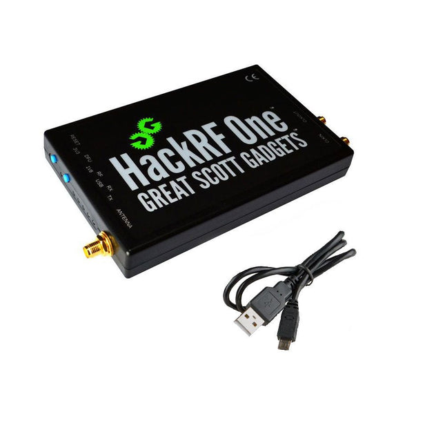
Great Scott Gadgets Great Scott Gadgets HackRF One SDR (1 MHz – 6 GHz)
New Version available! Click here! HackRF One is a Software Defined Radio (SDR) peripheral capable of transmission or reception of radio signals from 1 MHz to 6 GHz. Designed to enable test and development of modern and next generation radio technologies, HackRF One is an open source hardware platform that can be used as a USB peripheral or programmed for stand-alone operation. Specifications 1 MHz to 6 GHz operating frequency Half-duplex transceiver Up to 20 million samples per second 8-bit quadrature samples (8-bit I and 8-bit Q) Compatible with GNU Radio, SDR and more Software-configurable RX and TX gain and baseband filter Software-controlled antenna port power (50 mA at 3.3 V) SMA female antenna connector SMA female clock input and output for synchronization Convenient buttons for programming Internal pin headers for expansion Hi-Speed USB 2.0 USB-powered Open source hardware HackRF One is test equipment for RF systems. It has not been tested for compliance with regulations governing transmission of radio signals. You are responsible for using your HackRF One legally. Included 1x HackRF One SDR 1x Plastic enclosure 1x micro-USB cable Note: An antenna is not included. ANT500 is recommended as a starter antenna for HackRF One. Downloads Documentation GitHub Source code and hardware design files
-
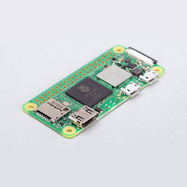
Raspberry Pi Foundation Raspberry Pi Zero 2 W
Raspberry Pi Zero 2 W is the successor to the breakthrough Raspberry Pi Zero W. The board incorporates a quad-core 64-bit Arm Cortex-A53 CPU, clocked at 1 GHz. At its heart is a Raspberry Pi RP3A0 system-in-package (SiP), integrating a Broadcom BCM2710A1 die with 512 MB of LPDDR2 SDRAM. The upgraded processor provides Raspberry Pi Zero 2 W with 40% more single-threaded performance, and five times more multi-threaded performance, than the original single-core Raspberry Pi Zero. Features 64-bit quad-core processor VideoCore IV GPU 512 MB LPDDR2 DRAM 802.11b/g/n wireless LAN Bluetooth 4.2 / Bluetooth Low Energy (BLE) MicroSD card slot Mini HDMI and USB 2.0 OTG ports Micro USB power HAT-compatible 40-pin header Composite video and reset pins via solder test points CSI camera connector Specifications SoC Broadcom BCM2710A1 CPU 64-bit ARM Cortex-A53 (4x 1 GHz) GPU Broadcom VideoCore VI RAM 512 MB LPDDR2 Wireless LAN 2.4 GHz IEEE 802.11b/g/n Bluetooth Bluetooth 4.2, BLE USB 1x micro USB (for data)1x micro USB (for power supply) GPIO HAT-compatible 40-pin GPIO header Video & Audio 1080P HD video & stereo audio via mini-HDMI connector SD card microSD (for operating system and storage) Power 5 VDC / 2.5 A (supplied via micro USB connector) Dimensions 65 x 30 x 5 mm Raspberry Pi Zero 2 W is footprint-compatible with earlier Zero models.
-
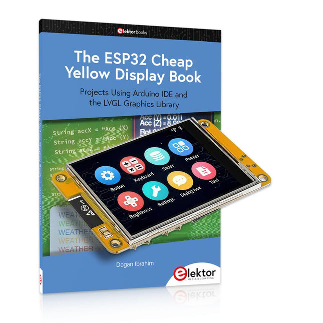
Elektor Bundles The ESP32 Cheap Yellow Display Bundle
Over 40 Fully Tested ESP32 Projects Using Arduino IDE and the LVGL Graphics Library This bundle includes the ESP32 Cheap Yellow Display (CYD) – a compact development board combining a standard ESP32 microcontroller with a 320x240 pixel TFT color display. The board also features multiple connectors for GPIO, serial communication (TX/RX), power, and ground. The built-in display is a major advantage, allowing users to create complex, graphics-based projects without the need for external LCDs or displays. The accompanying book introduces the CYD board's hardware and on-board connectors in detail. It provides a range of beginner to intermediate-level projects developed using the popular Arduino IDE 2.0. Both basic graphics functions and the powerful LVGL graphics library are covered, with practical projects illustrating each approach. All included projects have been fully tested and are ready to use. The book provides block diagrams, circuit schematics, complete code listings, and step-by-step explanations. With the LVGL library, readers can create modern, full-color graphical interfaces using widgets such as buttons, labels, sliders, calendars, keyboards, charts, tables, menus, animations, and more. ESP32 Cheap Yellow Display Board This development board (also known as "Cheap Yellow Display") is powered by the ESP-WROOM-32, a dual-core MCU with integrated Wi-Fi and Bluetooth capabilities. It operates at a main frequency of up to 240 MHz, with 520 KB SRAM, 448 KBROM, and a 4 MB Flash memory. The board features a 2.8-inch display with a resolution of 240x320 and resistive touch. Furthermore, the board includes a backlight control circuit, touch control circuit, speaker drive circuit, photosensitive circuit, and RGB-LED control circuit. It also provides a TF card slot, serial interface, DHT11 temperature and humidity sensor interface, and additional IO ports. The module supports development in Arduino IDE, ESP-IDE, MicroPython, and Mixly. Applications Image transmission for Smart Home device Wireless monitoring Smart agriculture QR wireless recognition Wireless positioning system signal And other IoT applications Specifications Microcontroller ESP-WROOM-32 (Dual-core MCU with integrated Wi-Fi and Bluetooth) Frequency Up to 240 MHz (computing power is up to 600 DMIPS) SRAM 520 KB ROM 448 KB Flash 4 MB Operating voltage 5 V Power consumption approx. 115 mA Display 2.8-inch color TFT screen (240 x 320) Touch Resistive Touch Driver chip ILI9341 Dimensions 50 x 86 mm Weight 50 g Downloads GitHub This bundle contains: The ESP32 Cheap Yellow Display Book (normal price: €35) ESP32 Cheap Yellow Display Board (normal price: €25) 1x ESP32 Dev Board with 2.8" Display and acrylic Shell 1x Touch pen 1x Connector cable 1x USB cable
€ 59,95€ 49,95
Best Price
-

Zhongdi ZD-915 Desoldering Station
The ZD-915 is a digital desoldering station with ESD protection and digital display of both the actual and set value on an LCD screen. This desoldering station has high power in a compact and robust housing and makes desoldering easy, because it can be operated with one hand. The ZD-915 features a soldering gun that houses a filter that catches any sucked material, so you only need to replace the filters to continue. There is also a temperature sensor in the tip so that temperature fluctuations can be quickly absorbed. Features The temperature is easily adjusted by simple up/down buttons. 140 W temperature controlled soldering station with adjustable range from 160°C to 480°C. The desoldering station is designed for lead free desoldering specially. The side of the station features a typical holder with sponge. An illuminated power on/off is also loacted on the front. Specifications Station Voltage supply 220-240 V Power consumption 140 W Vakuum pressure 600 mm HG Desoldering Gun Power consumption 24 V AC 80 WHeat up rating 130 W Temperature 160-480 °C Heating element Ceramic heater Included 1x ZD-915 Desoldering station 2x Spare soldering tip 3x Cleaning needle for desoldering tips 1x Spare filter for desoldering gun 1x Manual
€ 107,00
-
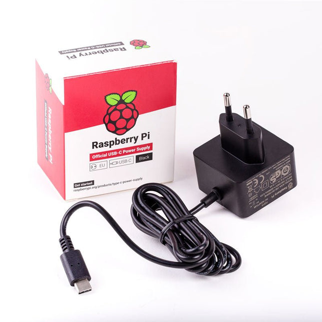
Raspberry Pi Foundation Official EU Power Supply for Raspberry Pi 4 (black)
The Raspberry Pi USB-C power supply is designed specifically to power the Raspberry Pi 4. The power supply features a USB-C cable and is available in four different models to suit different international power sockets, and in two colors. Specifications Output Output voltage +5.1 V DC Minimum load current 0 A Nominal load current 3.0 A Maximum power 15.3 W Load regulation ±5% Line regulation ±2% Ripple & noise 120 mVp-p Rise time 100 ms maximum to regulation limits for DC outputs Turn-on delay 3000 ms maximum at nominal input AC voltage and full load Protection Short circuit protectionOvercurrent protectionOver temperature protection Efficiency 81% minimum (output current from 100%, 75%, 50%, 25%)72% minimum at 10% load Output cable 1.5 m 18AWG Output connector USB-C Input Voltage range 100-240 V AC (rated)96-264 V AC (operating) Frequency 50/60 Hz ±3 Hz Current 0.5 A maximum Power consumption (no load) 0.075 W maximum Inrush current No damage shall occur, and the input fuse shall not blow Operating ambient temperature 0-40°C
-
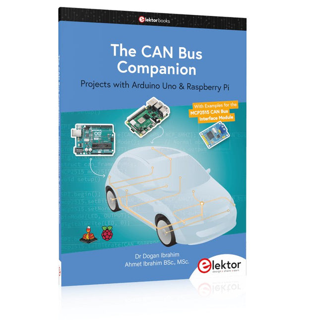
Elektor Publishing The CAN Bus Companion
This book details the use of the Arduino Uno and the Raspberry Pi 4 in practical CAN bus based projects. Using either the Arduino Uno or the Raspberry Pi with off-the-shelf CAN bus interface modules considerably ease developing, debugging, and testing CAN bus based projects. This book is written for students, practicing engineers, enthusiasts, and for everyone else wanting to learn more about the CAN bus and its applications. The book assumes that the reader has some knowledge of basic electronics. Knowledge of the C and Python programming languages and programming the Arduino Uno using its IDE and Raspberry Pi will be useful, especially if the reader intends to develop microcontroller-based projects using the CAN bus. The book should be a useful source of reference material for anyone interested in finding answers to questions such as: What bus systems are available for the automotive industry? What are the principles of the CAN bus? How can I create a physical CAN bus? What types of frames (or data packets) are available in a CAN bus system? How can errors be detected in a CAN bus system and how dependable is a CAN bus system? What types of CAN bus controllers exist? How do I use the MCP2515 CAN bus controller? How do I create 2-node Arduino Uno-based CAN bus projects? How do I create 3-node Arduino Uno-based CAN bus projects? How do I set the acceptance masks and acceptance filters? How do I analyze data on the CAN bus? How do I create 2-node Raspberry Pi-based CAN bus projects? How do I create 3-node Raspberry Pi-based CAN bus projects?
€ 34,95
Members: € 31,46
-

Elektor Labs Elektor Dual DC LISN (150 kHz – 200 MHz)
Measuring conducted emission is the simplest and most affordable method of getting some indication of whether a design can meet EMI/EMC requirements. A Line Impedance Stabilization Network (LISN) is an indispensable part of an EMC pre-compliance test setup. In cooperation with Würth Elektronik, Elektor has developed a 5 µH, 50 Ω Dual DC LISN that supports voltages up to 60 V and currents up to 10 A. The instrument measures RF interferences on both channels (the power supply) by means of 5-μH blocking inductances. The internal 10-dB attenuation network – one in each channel – contains a 3rd-order high-pass filter with a cutoff frequency of 9 kHz to protect the input of instruments like a spectrum analyzer from potentially harmful DC voltages or low frequencies coming from the EUT (Equipment Under Test). Specifications RF path Channels 2 (with clamping diodes) Bandwidth 150 kHz – 200 MHz Inductance 5 μH || 50 Ω Internal attenuation 10 dB Connectors SMA DC path Max. current < 10 ADC Max. voltage < 60 VDC DC resistance < 2 x 70 mΩ PCB size 94.2 x 57.4 mm Connectors 4-mm banana Hammond enclosure Type 1590N Dimensions 121 x 66 x 40 mm Included 1x 4-layer PCB with all SMT parts fitted 1x pre-drilled enclosure with ready-printed front panel layout 5x gold-plated, insulated, 4-mm banana sockets, rated for 24 A, 1 kV 1x Hammond enclosure 1590N1, Aluminum (Die-Cast Alloy) More Info Project on Elektor Labs: Dual DC LISN for EMC pre-compliance testing Elektor 9-10/2021: EMC Pre-Compliance Test for Your DC-Powered Project (Part 1) Elektor 11-12/2021: EMC Pre-Compliance Test for Your DC-Powered Project (Part 2)
-
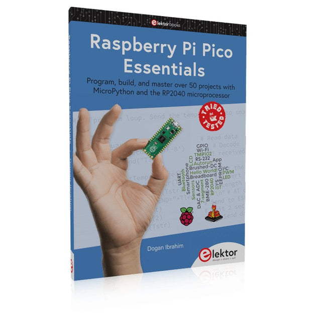
Elektor Publishing Raspberry Pi Pico Essentials
Program, build, and master over 50 projects with MicroPython and the RP2040 microprocessor The Raspberry Pi Pico is a high-performance microcontroller module designed especially for physical computing. Microcontrollers differ from single-board computers, like the Raspberry Pi 4, in not having an operating system. The Raspberry Pi Pico can be programmed to run a single task very efficiently within real-time control and monitoring applications requiring speed. The ‘Pico’ as we call it, is based on the fast, efficient, and low-cost dual-core ARM Cortex-M0+ RP2040 microcontroller chip running at up to 133 MHz and sporting 264 KB of SRAM, and 2 MB of Flash memory. Besides its large memory, the Pico has even more attractive features including a vast number of GPIO pins, and popular interface modules like ADC, SPI, I²C, UART, and PWM. To cap it all, the chip offers fast and accurate timing modules, a hardware debug interface, and an internal temperature sensor. The Raspberry Pi Pico is easily programmed using popular high-level languages such as MicroPython and or C/C++. This book is an introduction to using the Raspberry Pi Pico microcontroller in conjunction with the MicroPython programming language. The Thonny development environment (IDE) is used in all the projects described. There are over 50 working and tested projects in the book, covering the following topics: Installing the MicroPython on Raspberry Pi Pico using a Raspberry Pi or a PC Timer interrupts and external interrupts Analogue-to-digital converter (ADC) projects Using the internal temperature sensor and external temperature sensor chips Datalogging projects PWM, UART, I²C, and SPI projects Using Wi-Fi and apps to communicate with smartphones Using Bluetooth and apps to communicate with smartphones Digital-to-analogue converter (DAC) projects All projects given in the book have been fully tested and are working. Only basic programming and electronics experience is required to follow the projects. Brief descriptions, block diagrams, detailed circuit diagrams, and full MicroPython program listings are given for all projects described. Readers can find the program listings on the Elektor web page created to support the book.
€ 39,95
Members: € 35,96
-
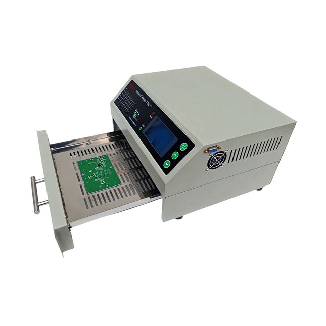
puhui Upgraded T-962 v2.0 Reflow Soldering Oven (Elektor Version)
This upgraded version 2.0 (available exclusively from Elektor) contains the following improvements: Enhanced protective earthing (PE) for furnace chassis Extra thermal insulation layer around furnace to reduce odors Connection to a computer, allowing curve editing on a PC Features such as constant temperature control and timing functions The infrared IC heater T-962 v2.0 is a microprocessor-controlled reflow oven that you can use for effectively soldering various SMD and BGA components. The whole soldering process can be completed automatically and it is very easy to use. This machine uses a powerful infrared emission and circulation of the hot air flow, so the temperature is being kept very accurate and evenly distributed. A windowed drawer is designed to hold the work-piece, and allows safe soldering techniques and the manipulation of SMDBGA and other small electronic parts mounted on a PCB assembly. The T-962 v2.0 may be used to automatically rework solder to correct bad solder joints, remove/replace bad components and complete small engineering models or prototypes. Features Large infrared soldering area Effective soldering area: 180 x 235 mm; this increases the usage range of this machine drastically and makes it an economical investment. Choice of different soldering cycles Parameters of eight soldering cycles are pre defined and the entire soldering process can completed automatically from Preheat, Soak and Reflow through to cool down. Special heat up and temperature equalization with all designs Uses up to 800 Watts of energy efficient Infrared heating and air circulation to re-flow solder. Ergonomic design, practical and easily operated Good build quality but at the same time light weight and a small footprint allows the T-962 v2.0 to be easily bench positioned transported or stored. Large number of available functions The T-962 v2.0 can solder most small parts of PCB boards, for example CHIP, SOP, PLCC, QFP, BGA etc. It is the ideal rework solution from single runs to on-demand small batch production. Specifications Soldering area (max) 180 x 235 mm (7.1 x 9.3") Power (max) 800 W Temperature range 0-280°C (32-536°F) Heating method Infrared Processing time 1~8 minutes Power supply 220 V AC/50 Hz Display LCD with Backlight Control mode 8 intelligent temperature curves Dimensions 310 x 290 x 170 mm (12.2 x 11.4 x 6.7") Weight 6.2 kg Included 1x T-962 v2.0 Reflow Soldering Oven (Elektor Version) 1x USB Stick (with Manual and Software) 2x Fuses 1x Power cord (EU) Downloads Manual
€ 299,00€ 259,00
Best Price
-
Raspberry Pi Foundation microSD Card pre-installed with Raspberry Pi OS (32 GB)
With this microSD (32 GB) with pre-installed Raspberry Pi OS you can start using your Raspberry Pi right away. Just plug it in and get started!
-
Elektor Publishing Develop your own Bluetooth Low Energy Applications
For Raspberry Pi, ESP32 and nRF52 with Python, Arduino and Zephyr Bluetooth Low Energy (BLE) radio chips are ubiquitous from Raspberry Pi to light bulbs. BLE is an elaborate technology with a comprehensive specification, but the basics are quite accessible. A progressive and systematic approach will lead you far in mastering this wireless communication technique, which is essential for working in low power scenarios. In this book, you’ll learn how to: Discover BLE devices in the neighborhood by listening to their advertisements. Create your own BLE devices advertising data. Connect to BLE devices such as heart rate monitors and proximity reporters. Create secure connections to BLE devices with encryption and authentication. Understand BLE service and profile specifications and implement them. Reverse engineer a BLE device with a proprietary implementation and control it with your own software. Make your BLE devices use as little power as possible. This book shows you the ropes of BLE programming with Python and the Bleak library on a Raspberry Pi or PC, with C++ and NimBLE-Arduino on Espressif’s ESP32 development boards, and with C on one of the development boards supported by the Zephyr real-time operating system, such as Nordic Semiconductor's nRF52 boards. Starting with a very little amount of theory, you’ll develop code right from the beginning. After you’ve completed this book, you’ll know enough to create your own BLE applications.
€ 39,95
Members: € 35,96


