ESP32-S3-GEEK is a geek development board with built-in USB-A port, 1.14-inch LCD screen, TF card slot and other peripherals. It supports 2.4 GHz WiFi and BLE 5, with built-in 16 MB Flash & 2 MB PSRAM, provides I²C port, UART port and GPIO header for more possibilities for your project.
Features
Adopts ESP32-S3R2 chip with Xtensa 32-bit LX7 dual-core processor, capable of running at 240 MHz
Built in 512 KB SRAM, 384 KB ROM, 2 MB of on-chip PSRAM, and onboard 16 MB Flash memory
Onboard 1.14-inch 240x135 pixels 65K color IPS LCD display
Integrated 2.4 GHz WiFi and Bluetooth LE wireless communication
WiFi supports Infrastructure BSS in Station, SoftAP, and Station + SoftAP modes
WiFi supports 1T1R mode with data rate up to 150 Mbps
Bluetooth supports high power mode (20 dBm)
Internal co-existence mechanism between Wi-Fi and Bluetooth to share the same antenna
Onboard 3-pin UART port, 3-pin GPIO header and 4-pin I²C port
Equipped with plastic case and cables
Provides online open-source demo and resources, more convenient for learning and development
Dimensions: 61.0 x 24.5 x 9.0 mm
Downloads
Wiki
The LILYGO TTGO T-Display-GD32 is a compact and minimalist development board featuring a powerful GD32VF103CBT6 RISC-V microcontroller.
Ideal for IoT applications, wearables, and rapid prototyping, it provides versatile connectivity options like GPIO, SPI, UART, and I²C interfaces. Thanks to its efficient RISC-V architecture and clear, high-quality screen, this board is perfect for small projects requiring graphical interfaces or data visualization in a space-saving form factor.
Specifications
Chipset
GD32VF103CBT6
FLASH
128 kB
SRAM
32 kB
On-board clock
108 MHz crystal oscillator
Working Voltage
2.7-3.6 V
Button
BOOT - RESET
LCD
ST7789 1.14" IPS 240 x 135
USB to TTL
CP2104
Modular interface
TIMER, UART, SPI, I²C, PWM, ADC, DAC, CAN, USBOTG
Working Temperature Range
−40~85°C
Peripheral
Button, RGB LED, SD slot, LCD
Power Supply Input
USB 5 V @ 1 A
Charging Current
500 mA
Battery Input
3.7-4.2 V
USB
USB-C
Dimensions
51.49 x 25.2 x 10 mm
Weight
10 g
Downloads
GitHub
The Arduino Nano is a complete Arduino-compatible single board computer that can be plugged directly into a 32-pin socket, a breadboard or a corresponding carrier board. It offers the complete Arduino functionality in very compact dimensions. Via the micro-USB socket, you can supply the board and circuit with power as well as conveniently transfer new programs to the controller. Technical details Pin headers for direct use on the pinboard Ideal for prototyping Programmable via free Arduino IDE Connection via mini USB socket Chipset CH340G Interfaces: I²C, UART, SPI Size: 45 x 18 mm Microcontroller ATmega328P-AU Operating Voltage 5 V Flash Memory 32 KB (2 KB used for Bootloader) SRAM 2 KB EEPROM 1 KB Digital Pins 22 (6 with PWM) Analog Pins 8 DC Current per I/O Pin 40 mA Input Voltage 7-12 V Downloads Datasheet User Guide
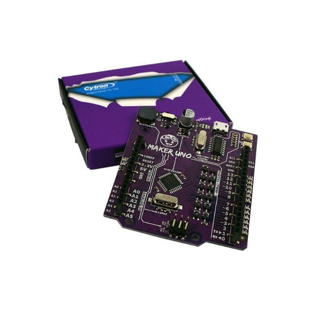
Features Piezo Buzzer: Acts as a simple audio output Micro USB Port Programmable Button 12 x LED: Provides visual output on board Specifications Microcontroller ATmega328P Programming IDE Arduino IDE Operating Voltage 5 V Digital I/O 20 PWM 6 Analog Input 6 (10-bit) UART 1 SPI 1 I2C 1 External Interrupt 2 Flash Memory 32 KB SRAM 2 KB EEPROM / Data Flash 1 KB Clock Speed 16 MHz DC Current I/O Pin 20 mA Power Supply USB only DC Current for 5 V USB Source DC Current for 3.3 V 500 mA USB to Serial Chip CH340G Programmable LED 12 at digital Pin 2 to 13 Programmable Push Button 1 at digital Pin 2 Piezo Buzzer 1 at digital Pin 8 Arduino vs Maker Uno
This affordable and increasingly powerful FPGA board is a fantastic starting point into the world of FPGAs and the heart of your next project. Finally, now that SparkFun builds this board, we added a Qwiic connector for easy I²C integration!
The Alchitry Au features a Xilinx Artix 7 XC7A35T-1C FPGA with over 33,000 logic cells and 256 MB of DDR3 RAM. The Au offers 102 3.3 V logic level IO pins, 20 of which can be switched to 1.8 V; Nine differential analogue inputs; Eight general-purpose LEDs; a 100 MHz on-board clock that can be manipulated internally by the FPGA; a USB-C connector to configure and power the board; and a USB to serial interface for data transfer. To make getting started even easier, all Alchitry boards have full Lucid support, a built-in library of useful components to use in your project, and a debugger!
Features
Artix 7 XC7A35T-1C - 33,280 logic cells
256 MB DDR3 RAM
102 IO pins (3.3 V logic level, 20 of them can be switched to 1.8 V for LVDS)
Nine differential analogue inputs (One dedicated, Eight mixed with digital IO)
USB-C to configure and power the board
Eight general-purpose LEDs
One button (typically used as a reset)
100 MHz on-board clock (can be multiplied internally by the FPGA)
Powered with 5 V through USB-C port, 0.1" holes, or headers
USB to serial interface for data transfer (up to 12 Mbaud)
Qwiic Connector
Dimensions: 65 x 45 mm
Downloads
Datasheet
Schematic
3D Model (IGES File)
Element Eagle Library
Features Build in USB to Serial interface Build-in PCB antenna Powered by Pineseed BL602 SoC using Pinenut model: 12S stamp 2 MB Flash USB-C connection Suitable to breadboard BIY project On board three color LEDs output Dimensions: 25.4 x 44.0 mm Note: USB cable is not included.
Ready to start developing Artificial Intelligence (AI) applications? The NVIDIA Jetson Nano Developer Kit makes the power of modern AI accessible to makers, developers, and students.
When you think of NVIDIA, you probably think about graphics cards and GPUs, and rightfully so. Nvidia's track record guarantees that the Jetson Nano has enough power to run even the most demanding of tasks.
The NVIDIA Jetson Nano Developer Kit is compatible with Nvidia's JetPack SDK and enables image classification and object detection amongst many applications.
Applications
The NVIDIA Jetson Nano Developer Kit can run multiple neural networks in parallel for applications like:
Image classification
Segmentation
Object detection
Speech processing
Specifications
GPU
128-core Maxwell
CPU
Quad-core ARM A57 @ 1.43 GHz
Memory
4 GB 64-bit LPDDR4 25.6 GB/s
Storage
microSD (not included)
Video Encode
4K @ 30 | 4x 1080p @ 30 | 9x 720p @ 30 (H.264/H.265)
Video Decode
4K @ 60 | 2x 4K @ 30 | 8x 1080p @ 30 | 18x 720p @ 30 (H.264/H.265)
Camera
1 x MIPI CSI-2 DPHY lanes
Connectivity
Gigabit Ethernet, M.2 Key E
Display
HDMI 2.0 and eDP 1.4
USB
4x USB 3.0, USB 2.0 Micro-B
Interfaces
GPIO, I²C, I²S, SPI, UART
Dimensions
100 x 80 x 29 mm
Included
NVIDIA Jetson Nano module and carrier board
Small paper card with quick start and support information
Folded paper stand
Downloads
JetPack SDK
Documentation
Tutorials
Online course
Wiki
SwiftIO offers a full Swift compiler and framework environment that runs on the microcontroller. The SwiftIO board is a compact electronic circuit board that runs Swift on the bare metal, giving you a system that can be used to control all kinds of electronic projects.
Features
NXP i.MX RT1052 Crossover Processor with ARM Cortex-M7 core @ 600 MHz
8 MB SPI Flash, 32 MB SDRAM
On-board DAPLink debugger
On-board USB to UART for serial communication
On-board RGB LED
On-board SD socket
46x GPIO, 12x ADC, 14x PWM, 4x UART, 2x I²C, 2x SPI etc.
Many additional advanced features to meet the needs of advanced users
Zephyr RTOS support
MadMachine IDE is the premier integrated development environment for SwiftIO, which makes it easy to write Swift code and download it to the board.
Features
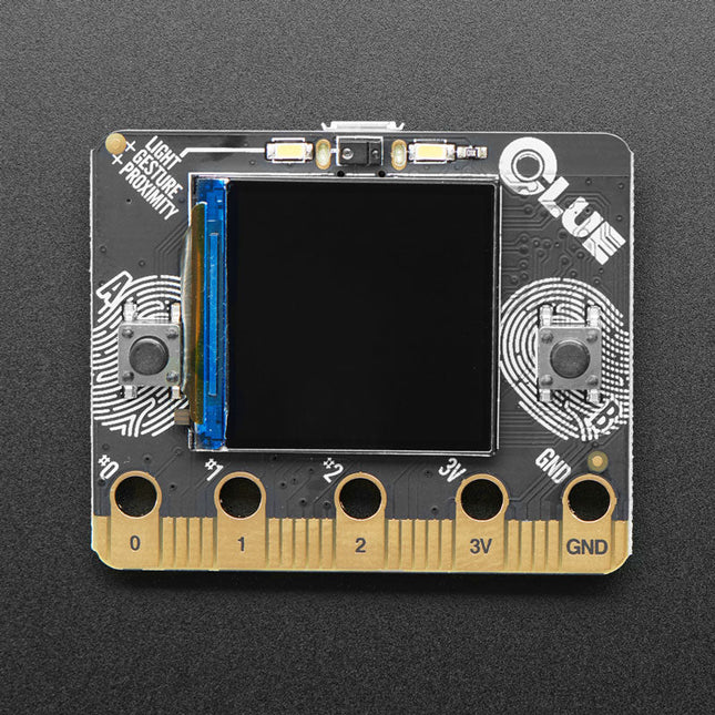
Nordic nRF52840 Bluetooth LE processor – 1 MB of Flash, 256KB RAM, 64 MHz Cortex M4 processor
1.3″ 240×240 Color IPS TFT display for high-resolution text and graphics
Power it from any 3-6V battery source (internal regulator and protection diodes)
Two A / B user buttons and one reset button
ST Micro series 9-DoF motion – LSM6DS33 Accel/Gyro + LIS3MDL magnetometer
APDS9960 Proximity, Light, Color, and Gesture Sensor
PDM Microphone sound sensor
SHT Humidity
BMP280 temperature and barometric pressure/altitude
RGB NeoPixel indicator LED
2 MB internal flash storage for datalogging, images, fonts or CircuitPython code
Buzzer/speaker for playing tones and beeps
Two bright white LEDs in front for illumination / color sensing
Qwiic / STEMMA QT connector for adding more sensors, motor controllers, or displays over I²C. You can plug in GROVE I²C sensors by using an adapter cable.
Programmable with Arduino IDE or CircuitPython
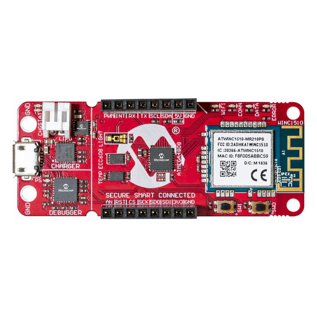
The AVR-IoT WA development board combines a powerful ATmega4808 AVR MCU, an ATECC608A CryptoAuthentication secure element IC and the fully certified ATWINC1510 Wi-Fi network controller – which provides the most simple and effective way to connect your embedded application to Amazon Web Services (AWS). The board also includes an on-board debugger, and requires no external hardware to program and debug the MCU.
Out of the box, the MCU comes preloaded with a firmware image that enables you to quickly connect and send data to the AWS platform using the on-board temperature and light sensors. Once you are ready to build your own custom design, you can easily generate code using the free software libraries in Atmel START or MPLAB Code Configurator (MCC).
The AVR-IoT WA board is supported by two award-winning Integrated Development Environments (IDEs) – Atmel Studio and Microchip MPLAB X IDE – giving you the freedom to innovate with your environment of choice.
Features
ATmega4808 microcontroller
Four user LED’s
Two mechanical buttons
mikroBUS header footprint
TEMT6000 Light sensor
MCP9808 Temperature sensor
ATECC608A CryptoAuthentication™ device
WINC1510 WiFi Module
On-board Debugger
Auto-ID for board identification in Atmel Studio and Microchip MPLAB X
One green board power and status LED
Programming and debugging
Virtual COM port (CDC)
Two DGI GPIO lines
USB and battery powered
Integrated Li-Ion/LiPo battery charger
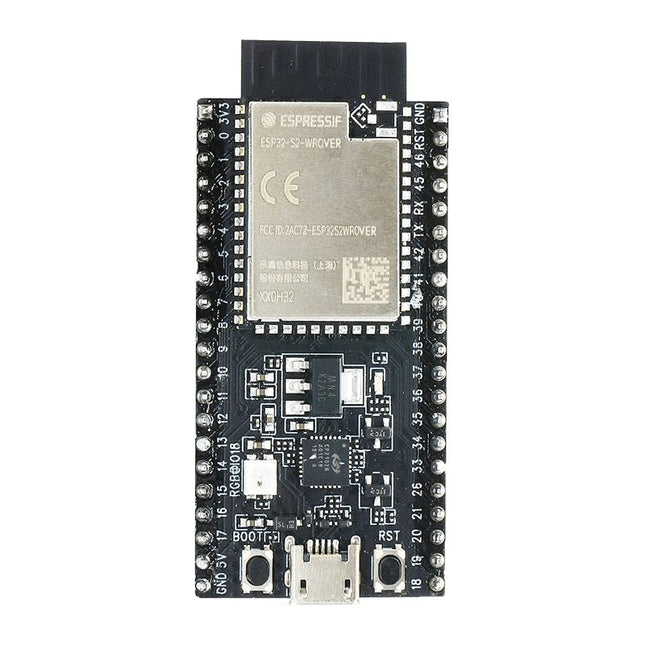
ESP32-S2-Saola-1R is a small-sized ESP32-S2 based development board. Most of the I/O pins are broken out to the pin headers on both sides for easy interfacing. Developers can either connect peripherals with jumper wires or mount ESP32-S2-Saola-1R on a breadboard.ESP32-S2-Saola-1R is equipped with the ESP32-S2-WROVER module, a powerful, generic Wi-Fi MCU module that has a rich set of peripherals. It is an ideal choice for a wide variety of application scenarios relating to Internet of Things (IoT), wearable electronics and smart home. The board a PCB antenna and features a 4 MB external SPI flash and an additional 2 MB SPI Pseudo static RAM (PSRAM).FeaturesMCU
ESP32-S2 embedded, Xtensa® single-core 32-bit LX7 microprocessor, up to 240 MHz
128 KB ROM
320 KB SRAM
16 KB SRAM in RTC
WiFi
802.11 b/g/n
Bit rate: 802.11n up to 150 Mbps
A-MPDU and A-MSDU aggregation
0.4 µs guard interval support
Center frequency range of operating channel: 2412 ~ 2484 MHz
Hardware
Interfaces: GPIO, SPI, LCD, UART, I²C, I²S, Camera interface, IR, pulse counter, LED PWM, TWAI (compatible with ISO 11898-1), USB OTG 1.1, ADC, DAC, touch sensor, temperature sensor
40 MHz crystal oscillator
4 MB SPI flash
Operating voltage/Power supply: 3.0 ~ 3.6 V
Operating temperature range: –40 ~ 85 °C
Dimensions: 18 × 31 × 3.3 mm
Applications
Generic Low-power IoT Sensor Hub
Generic Low-power IoT Data Loggers
Cameras for Video Streaming
Over-the-top (OTT) Devices
USB Devices
Speech Recognition
Image Recognition
Mesh Network
Home Automation
Smart Home Control Panel
Smart Building
Industrial Automation
Smart Agriculture
Audio Applications
Health Care Applications
Wi-Fi-enabled Toys
Wearable Electronics
Retail & Catering Applications
Smart POS Machines
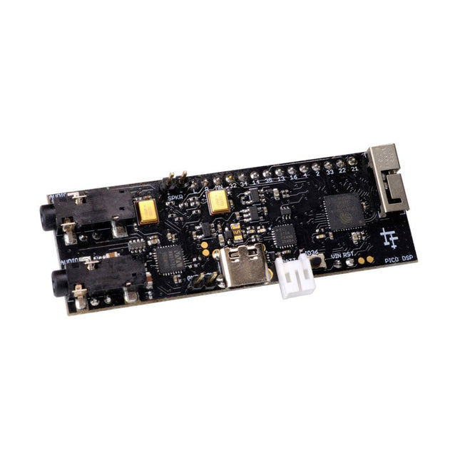
PÚCA DSP is an open-source, Arduino-compatible ESP32 development board for audio and digital signal processing (DSP) applications with expansive audio-processing features. It provides audio inputs, audio outputs, a low-noise microphone array, an integrated test-speaker option, additional memory, battery-charge management, and ESD protection all on a small, breadboard-friendly PCB.
Synthesizers, Installations, Voice UI, and More
PÚCA DSP can be used for a wide range of DSP applications, including but not limited to those in the fields of music, art, creative technology, and adaptive technology. Music-related examples include digital-music synthesis, mobile recording, Bluetooth speakers, wireless line-level directional microphones, and the design of smart musical instruments. Art-related examples include acoustic sensor networks, sound-art installations, and Internet-radio applications. Examples related to creative and adaptive technology include voice user interface (VUI) design and Web audio for the Internet of Sounds.
Compact, Integrated Design
PÚCA DSP was designed for portability. When used with an external 3.7 V rechargeable battery, it can be deployed almost anywhere or integrated into just about any device, instrument, or installation. Its design emerged from months of experimentation with various ESP32 development boards, DAC breakout boards, ADC breakout boards, Microphone breakout boards, and audio-connector breakout boards, and – despite its diminutive size – it manages to provide all of that functionality in a single board. And it dos so without compromising signal quality.
Specifications
Processor & Memory
Espressif ESP32 Pico D4 Processor
32-bit dual core 80 MHz / 160 MHz / 240 MHz
4 MB SPI Flash with 8 MB additional PSRAM (Original Edition)
Wireless 2.4 GHz Wi-Fi 802.11b/g/n
Bluetooth BLE 4.2
3D Antenna
Audio
Wolfson WM8978 Stereo Audio Codec
Audio Line In on 3.5 mm stereo onnector
Audio Headphone / Line Out on 3.5 mm stereo connector
Stereo Aux Line In, Audio Mono Out routed to GPIO Header
2x Knowles SPM0687LR5H-1 MEMS Microphones
ESD protection on all audio inputs and outputs
Support for 8, 11.025, 12, 16, 22.05, 24, 32, 44.1 and 48 kHz sample rates
1 W Speaker Driver, routed to GPIO Header
DAC SNR 98 dB, THD -84 dB (‘A’ weighted @ 48 kHz)
ADC SNR 95 dB, THD -84 dB (‘A’ weighted @ 48 kHz)
Line input impedance: 1 MOhm
Line output impedance: 33 Ohm
Form Factor and Connectivity
Breadboard friendly
70 x 24 mm
11x GPIO pins broken out to 2.54 mm pitch header, with access to both ESP32 ADC channels, JTAG and capacitive touch pins
USB 2.0 over USB Type C connector
Power
3.7/4.2 V Lithium Polymer Rechargeable Battery, USB or external 5 V DC power source
ESP32 and Audio Codec can be placed into low power modes under software control
Battery voltage level detection
ESD protection on USB data bus
Downloads
GitHub
Datasheet
Links
Crowd Supply Campaign (includes FAQs)
Hardware Overview
Programming the Board
The Audio Codec
The SparkFun RedBoard Qwiic is an Arduino-compatible board that combines features of different Arduinos with the Qwiic Connect System.
Features
ATmega328 microcontroller with Optiboot Bootloader
R3 Shield Compatible
CH340C Serial-USB Converter
3.3 V to 5 V Voltage Level Jumper
A4 / A5 Jumpers
AP2112 Voltage Regulator
ISP Header
Input voltage: 7 V - 15 V
1 Qwiic Connector
16 MHz Clock Speed
32 k Flash Memory
All SMD Construction
Improved Reset Button
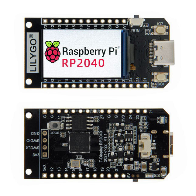
LILYGO T-Display RP2040 Raspberry Pi Module 1.14-inch LCD Development Board This board is based on a Raspberry Pi Pico RP2040 with Dual Cortex-M0+ and 4 MB Flash memory. It is equipped with a 1.14-inch full color IPS display. The ST7789V display has a resolution of 135 x 240 pixels and is connected via the SPI interface. Specifications MCU RP2040 Dual ARM Cortex M0+ Flash 4 MB Bus interfaces 2x UART, 2x SPI, 2x I²C, 6x PWM Programming language C/C++, MicroPython Support machine learning library TensorFlow Lite Onboard functions Buttons: IO06+IO07, battery power detection TFT Display 1.14-inch ST7789V IPS LCD Resolution 135 x 240, full color Interface 4-Wire SPI interface Operating temperature -20°C ~ +70°C Working power supply 3.3 V Connector JST-GH 1.25 mm 2-pin Included LILYGO T-Display RP2040 Unsoldered headers JST cable Downloads Pinout GitHub
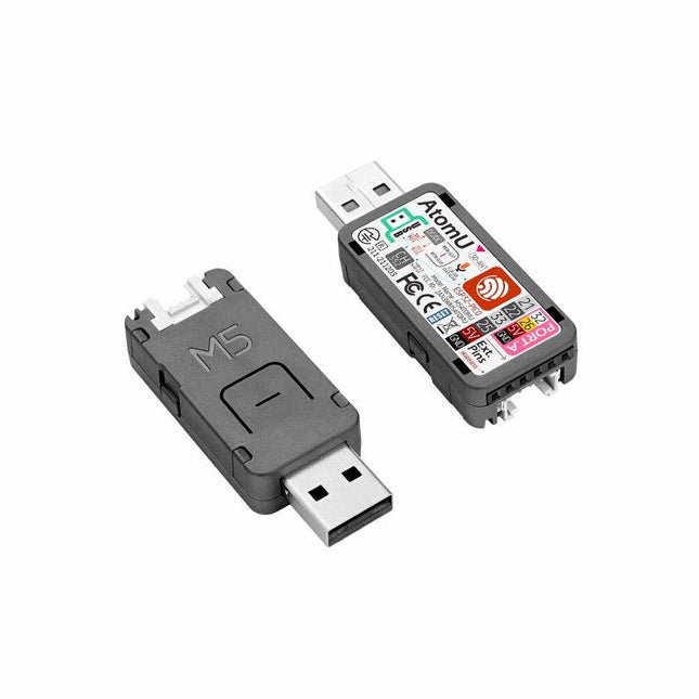
ATOM U is a compact low-power consumption speech recognition IoT development kit. It adopts an ESP32 chipset, equipped with 2 low-power Xtensa 32-bit LX6 microprocessors with the main frequency of up to 240 MHz. Built-in USB-A interface, IR emitter, programmable RGB LED. Plug-and-play, easy to upload and download programs. Integrated Wi-Fi and digital microphone SPM1423 (I2S) for the clear sound record. suitable for HMI, Speech-to-Text (STT). Low-code development ATOM U supports UIFlow graphical programming platform, scripting-free, cloud push; Fully compatible with Arduino, MicroPython, ESP32-IDF, and other mainstream development platforms, to quickly build various applications. High integration ATOM U contains a USB-A port for programming/power supply, IR emitter, programmable RGB LED x1, button x1; Finely tuned RF circuit, providing stable and reliable wireless communication. Strong expandability ATOM U is easy access to M5Stack's hardware and software system. Features ESP32-PICO-D4 (2.4GHz Wi-Fi dual mode) Integrated programmable RGB LED and button Compact design Built-in IR emitter Expandable pinout and GROVE port Development platform: UIFlow MicroPython Arduino Specifications ESP32-PICO-D4 240MHz dual core, 600 DMIPS, 520KB SRAM, 2.4G Wi-Fi Microphone SPM1423 Microphone sensitivity 94 dB SPL@1 KHz Typical value: -22 dBFS Microphone signal-to-noise ratio 94 dB SPL@1 KHz, A-weighted Typical value: 61.4 dB Standby working current 40.4 mA Support input sound frequency 100 Hz ~ 10 KHz Support PDM clock frequency 1.0 ~ 3.25 MHz Weight 8.4 g Product size 52 x 20 x 10 mm Downloads Documentation
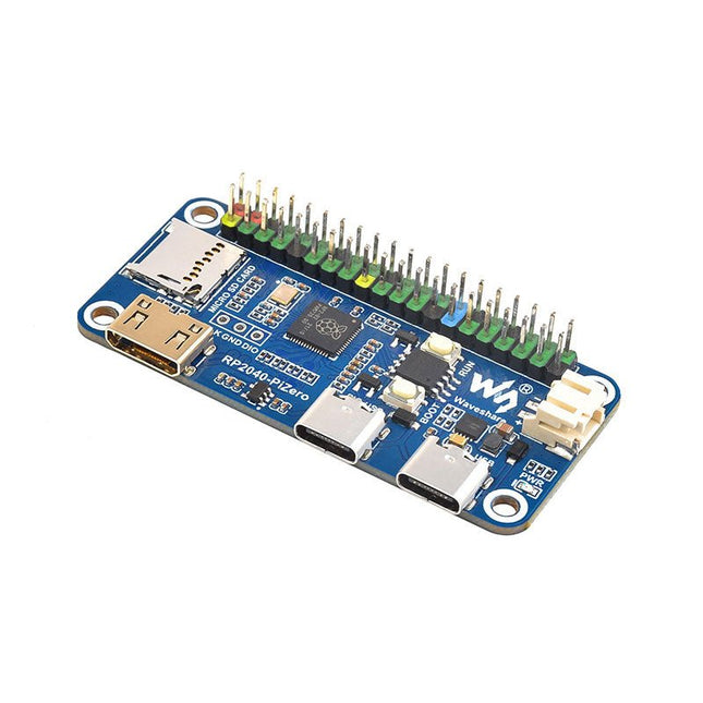
Waveshare RP2040-PiZero is a high-performance and cost-effective microcontroller board with onboard DVI interface, TF card slot and PIO-USB port, compatible with Raspberry Pi 40-pin GPIO header, easy to develop and integrate into the products.
Features
RP2040 microcontroller chip designed by Raspberry Pi
Dual-core ARM Cortex M0+ processor, flexible clock running up to 133 MHz
264 KB of SRAM, and 16 MB of onboard Flash memory
Onboard DVI interface can drive most HDMI screens (DVI compatibility required)
Supports using as a USB host or slave via onboard PIO-USB port
Onboard TF card slot for reading and writing TF card
Onboard Lithium battery recharge/discharge header, suitable for mobile scenarios
USB 1.1 with device and host support
Drag-and-drop programming using mass storage over USB
Low-power sleep and dormant modes
2x SPI, 2x I²C, 2x UART, 4x 12-bit ADC, 16x controllable PWM channels
Accurate clock and timer on-chip
Temperature sensor
Accelerated floating-point libraries on-chip
Downloads
Wiki
The T-Journal is a cheap ESP32 Camera Development Board that features an OV2640 camera, an antenna, a 0.91-inch OLED display, some exposed GPIOs, and a micro-USB interface. It makes it easy and quick to upload code to the board. Specifications Chipset Expressif-ESP32-PCIO-D4 240 MHz Xtensa single-/dual-core 32-bit LX6 microprocessor FLASH QSPI flash/SRAM, up to 4x 16 MB SRAM 520 kB SRAM KEY reset, IO32 Display 0.91' SSD1306 Power indicator lamp red USB to TTL CP2104 Camera OV2640, 2 Megapixel Steering engine analog servo On-board clock 40 MHz crystal oscillator Working voltage 2.3-3.6 V Working current about 160 mA Working temperature range -40℃ ~ +85℃ Size 64.57 x 23.98 mm Power Supply USB 5 V/1 A Charging current 1 A Battery 3.7 V lithium battery WiFi Standard FCC/CE/TELEC/KCC/SRRC/NCC (ESP32-chip) Protocol 802.11 b/g/n/e/i (802.11n, speed up to 150 Mbps) A-MPDU and A-MSDU polymerization, support 0.4 μS Protection interval Frequency range 2.4 GHz~2.5 GHz (2400 M ~ 2483.5 M) Transmit Power 22 dBm Communication distance 300m Bluetooth Protocol meet bluetooth v4.2BR/EDR and BLE standard Radio frequency with -98 dBm sensitivity NZIF receiver Class-1, Class-2 & Class-3 emitter AFH Audio frequency CVSD & SBC audio frequency Software Wifi Mode Station/SoftAP/SoftAP+Station/P2P Security mechanism WPA/WPA2/WPA2-Enterprise/WPS Encryption Type AES/RSA/ECC/SHA Firmware upgrade UART download/OTA(Through network/host to download and write firmware) Software Development Support cloud server development /SDK for user firmware development Networking protocol IPv4, IPv6, SSL, TCP/UDP/HTTP/FTP/MQTT User Configuration AT + Instruction set, cloud server, Android/iOS app OS FreeRTOS Included 1x ESP32 Camera Module (Normal Lens) 1x Wi-Fi Antenna 1x Power Line Downloads Camera library for Arduino
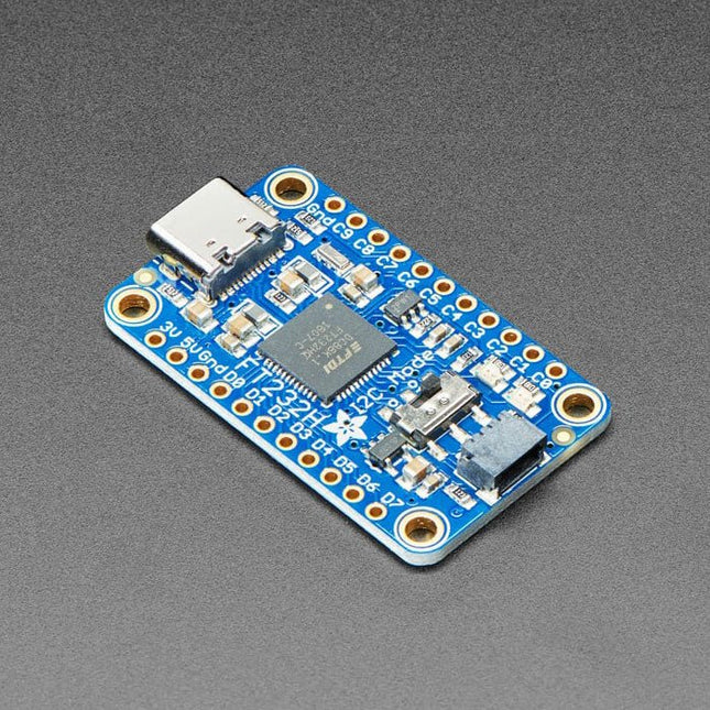
Wouldn't it be cool to drive a tiny OLED display, read a color sensor, or even just flash some LEDs directly from your computer? Sure you can program an Arduino or Trinket to talk to these devices and your computer, but why can't your computer just talk to those devices and sensors itself? Well, now your computer can talk to devices using the Adafruit FT232H breakout board! What can the FT232H chip do? This chip from FTDI is similar to their USB to serial converter chips but adds a 'multi-protocol synchronous serial engine' which allows it to speak many common protocols like SPI, I²C, serial UART, JTAG, and more! There's even a handful of digital GPIO pins that you can read and write to do things like flash LEDs, read switches or buttons, and more. The FT232H breakout is like adding a little swiss army knife for serial protocols to your computer! This chip is powerful and useful to have when you want to use Python (for example) to quickly iterate and test a device that uses I²C, SPI or plain general purpose I/O. There's no firmware to deal with, so you don't have to deal with how to 'send data to and from an Arduino which is then sent to and from' an electronic sensor or display or part. This breakout has an FT232H chip and an EEPROM for onboard configuration. Specifications Dimensions: 23 x 38 x 4 mm (0.9 x 1.5 x 0.2') Weight: 3.4 g Downloads CAD Files
ESP32-S2-Saola-1M is a small-sized ESP32-S2 based development board. Most of the I/O pins are broken out to the pin headers on both sides for easy interfacing. Developers can either connect peripherals with jumper wires or mount ESP32-S2-Saola-1M on a breadboard.
ESP32-S2-Saola-1M is equipped with the ESP32-S2-WROOM module, a powerful, generic Wi-Fi MCU module that has a rich set of peripherals. It is an ideal choice for a wide variety of application scenarios relating to Internet of Things (IoT), wearable electronics and smart home. The board a PCB antenna and features a 4 MB external SPI flash.
Features
MCU
ESP32-S2 embedded, Xtensa® single-core 32-bit LX7 microprocessor, up to 240 MHz
128 KB ROM
320 KB SRAM
16 KB SRAM in RTC
WiFi
802.11 b/g/n
Bit rate: 802.11n up to 150 Mbps
A-MPDU and A-MSDU aggregation
0.4 µs guard interval support
Center frequency range of operating channel: 2412 ~ 2484 MHz
Hardware
Interfaces: GPIO, SPI, LCD, UART, I²C, I²S, Camera interface, IR, pulse counter, LED PWM, TWAI (compatible with ISO 11898-1), USB OTG 1.1, ADC, DAC, touch sensor, temperature sensor
40 MHz crystal oscillator
4 MB SPI flash
Operating voltage/Power supply: 3.0 ~ 3.6 V
Operating temperature range: –40 ~ 85 °C
Dimensions: 18 × 31 × 3.3 mm
Applications
Generic Low-power IoT Sensor Hub
Generic Low-power IoT Data Loggers
Cameras for Video Streaming
Over-the-top (OTT) Devices
USB Devices
Speech Recognition
Image Recognition
Mesh Network
Home Automation
Smart Home Control Panel
Smart Building
Industrial Automation
Smart Agriculture
Audio Applications
Health Care Applications
Wi-Fi-enabled Toys
Wearable Electronics
Retail & Catering Applications
Smart POS Machines
The OKdo E1 is an ultra-low-cost Development Board based on the NXP LPC55S69JBD100 dual-core Arm Cortex-M33 microcontroller. The E1 board is perfect for Industrial IoT, building control and automation, consumer electronics, general embedded and secure applications.
Features
Processor with Arm TrustZone, Floating Point Unit (FPU) and Memory Protection Unit (MPU)
CASPER Crypto co-processor to enable hardware acceleration for certain asymmetric cryptographic algorithms
PowerQuad Hardware Accelerator for fixed and floating point DSP functions
SRAM Physical Unclonable Function (PUF) for key generation, storage and reconstruction
PRINCE module for real-time encryption and decryption of flash data
AES-256 and SHA2 engines
Up to Nine Flexcomm interfaces. Each Flexcomm interface can be selected by software to be a USART, SPI, I²C, and I²S interface
USB 2.0 High-Speed Host/Device controller with on-chip PHY
USB 2.0 Full-Speed Host/Device controller with on-chip PHY
Up to 64 GPIOs
Secure digital input/output (SD/MMC and SDIO) card interface
Specifications
LPC55S69JBD100 640kbyte flash microcontroller
In-built CMSIS-DAP v1.0.7 debugger based on LPC11U35
Internal PLL support up to 100MHz operation, 16MHz can be mounted for full 150MHz operation.
SRAM 320kB
32kHz crystal for real-time clock
4 user switches
3-colour LED
User USB connector
2-off 16-way expansion connectors
UART over USB virtual COM port
The LILYGO T-Panel S3 is a versatile development board designed for IoT applications, featuring a 4-inch IPS LCD with a 480x480 resolution.
Powered by the ESP32-S3 microcontroller, it offers 2.4 GHz Wi-Fi and Bluetooth 5 (LE) connectivity, with 16 MB of flash memory and 8 MB of PSRAM. The board supports development environments such as Arduino, PlatformIO-IDE, and MicroPython. Notably, it includes a capacitive touch interface, enhancing user interaction capabilities. Onboard functions comprise Boot (IO00), Reset, and two additional keys, providing flexibility for various applications. This combination of features makes the T-Panel S3 suitable for a wide range of IoT projects and smart device control interfaces.
Specifications
MCU1
ESP32-S3
Flash
16 MB
PSRAM
8 MB
Wireless Connectivity
2.4 GHz Wi-Fi + Bluetooth 5 (LE)
MCU2
ESP32-H2
Flash
4 MB
Wireless Connectivity
IEEE 802.15.4 + Bluetooth 5 (LE)
Developing
Arduino, PlatformIO-IDE, Micropython
Display
4.0" 480x480 IPS ST7701S LCD
Resolution
480 x 480 (RGB)
Interface
SPI + RGB
Compatibility library
Arduino_ GFX, LVGL
Onboard functions
QWiiCx2 + TF Card + AntennaESP32 4x Button= S3(Boot + RST) + H2(Boot + RST)
Transceiver Module
RS485
Using bus communication protocol
UART
Included
1x T-Panel S3
1x Female pin (2x 8x1.27)
Downloads
GitHub
ESP32-S3-EYE is a small-sized AI development board. It is based on the ESP32-S3 SoC and ESP-WHO, Espressif’s AI development framework. The ESP32-S3-EYE board consists of two parts: the main board (ESP32-S3-EYE-MB) features the ESP32-S3-WROOM-1 module, a 2-Megapixel camera, a SD card slot, a digital microphone, a USB port, and function buttons; and the sub board (ESP32-S3-EYE-SUB) integrates an LCD display. The main board and sub board are connected through pin headers. ESP32-S3-EYE offers plenty of storage, with an 8 MB Octal PSRAM and a 8 MB flash. It also supports image transmission via Wi-Fi and debugging through a Micro-USB port. Specifications Camera The 2 MP camera OV2640 has a 66.5° field of view and a maximum resolution of 1600x1200. You can change the resolution when developing applications. Module Power LED The LED (green) turns on when USB power is connected to the board. If it is not turned on, it indicates either the USB power is not supplied, or the 5 V to 3.3 V LDO is broken. Software can configure GPIO3 to set different LED statuses (turned on/off, flashing) for different statuses of the board. Note: GPIO3 must be set up in open-drain mode. Pulling GPIO3 up may burn the LED. Pin Headers Connect the female headers on the sub board. 5 V to 3.3 V LDO Power regulator that converts a 5 V supply into a 3.3 V output for the module. Digital Microphone The digital I²S MEMS microphone features 61 dB SNR and –26 dBFS sensitivity, working at 3.3 V. FPC Connector Connects the main board and the sub board. Function Button There are six function buttons on the board. Users can configure any functions as needed except for the RST button. ESP32-S3-WROOM-1 The ESP32-S3-WROOM-1 module embeds the ESP32-S3R8 chip variant that provides Wi-Fi and Bluetooth 5 (LE) connectivity, as well as dedicated vector instructions for accelerating neural network computing and signal processing. On top of the integrated 8 MB Octal SPI PSRAM offered by the SoC, the module also comes with 8 MB flash, allowing for fast data access. ESP32-S3-WROOM-1U module is also supported. MicroSD Card Slot Used for inserting a MicroSD card to expand memory capacity. 3.3 V to 1.5 V LDO Power regulator that converts a 3.3 V supply into a 1.5 V output for the camera. 3.3 V to 2.8 V LDO Power regulator that converts a 3.3 V supply into a 2.8 V output for the camera. USB Port A Micro-USB port used for 5 V power supply to the board, as well as for communication with the chip via GPIO19 and GPIO20. Battery Soldering Points Used for soldering a battery socket to connect an external Li-ion battery that can serve as an alternative power supply to the board. If you use an external battery, make sure it has built-in protection circuit and fuse. The recommended specifications of the battery: capacity > 1000 mAh, output voltage 3.7 V, input voltage 4.2 V – 5 V. Battery Charger Chip 1 A linear Li-ion battery charger (ME4054BM5G-N) in ThinSOT package. The power source for charging is the USB Port. Battery Red LED When the USB power is connected to the board and a battery is not connected, the red LED blinks. If a battery is connected and being charged, the red LED turns on. When the battery is fully charged, it turns off. Accelerometer Three-axis accelerometer (QMA7981) for screen rotation, etc.
Arduino, MicroPython, and CircuitPython-compatible compact development board powered by Raspberry Pi RP2040
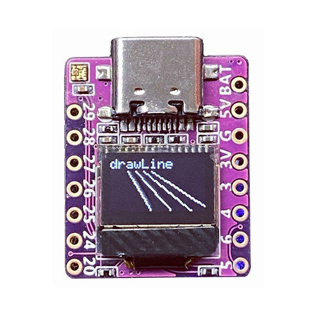
RP2040-0.42LCD is a high-performance development board with integrated 0.42" LCD (70x40 resolution) with flexible digital interfaces.
It incorporates Raspberry Pi's RP2040 microcontroller chip. The RP2040 features a dual-core Arm Cortex-M0+ processor clocked at 133 MHz with 264 KB internal SRAM and 2 MB flash storage.
Specifications
SoC
Raspberry Pi RP2040 dual-core Cortex-M0+ microcontroller at up to 125 MHz, with 264 KB SRAM
Storage
2 MB SPI flash
Display
0.42-inch OLED
USB
1x USB Type-C port for power and programming
Expansion
– Qwiic I²C connector– 7-pin and 8-pin headers with up to 11x GPIOs, 2x SPI, 2x I²C, 4x ADC, 1x UART, 5 V, 3.3 V, VBAT, GND
Misc
– Reset and Boot buttons– RGB LED, power LED
Power supply
– 5 V via USB-C port or Vin– VBAT pin for battery input– 3.3 V regulator with 500 mA peak output
Dimensions
23.5 x 18 mm
Weight
2.5 g
Downloads
GitHub
The iCEBreaker FPGA board is an open-source educational FPGA development board.
The iCEBreaker is great for classes and workshops teaching the use of the open source FPGA design flow through Yosys, nextpnr, IceStorm, Icarus Verilog, Amaranth HDL and others. This means the board is low cost and has a nice set of features to allow for the design of interesting classes and workshop exercises. At the same time it allows the user to use the proprietary vendor tools if they choose to.
After the workshop the boards can be easily used as a development board as most GPIO are exposed, broken out and configurable through jumpers on the back of the board. There is only a minimal amount of buttons and LED that can't be disconnected and used for your own purposes.
Documentation
Workshop