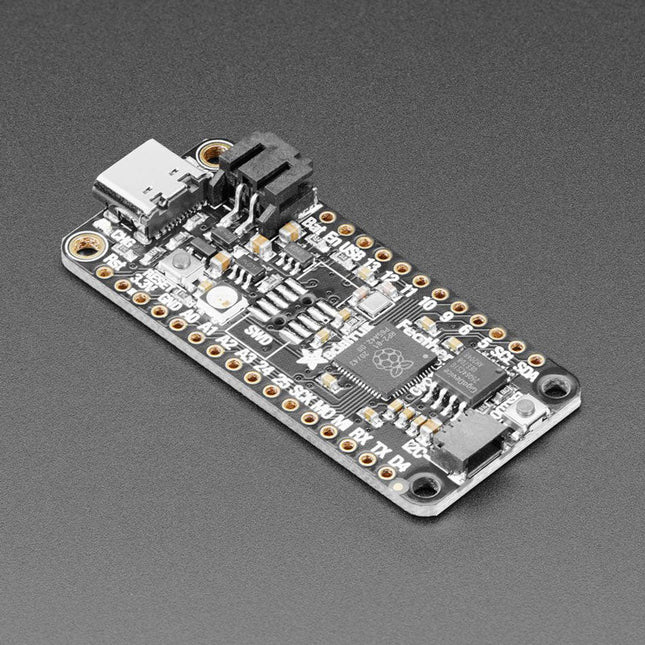
Inside the RP2040 is a 'permanent ROM' USB UF2 bootloader. What that means is when you want to program new firmware, you can hold down the BOOTSEL button while plugging it into USB (or pulling down the RUN/Reset pin to ground) and it will appear as a USB disk drive you can drag the firmware onto. Folks who have been using Adafruit products will find this very familiar – Adafruit uses the technique on all thier native-USB boards. Just note you don't double-click reset, instead hold down BOOTSEL during boot to enter the bootloader!
The RP2040 is a powerful chip, which has the clock speed of our M4 (SAMD51), and two cores that are equivalent to our M0 (SAMD21). Since it is an M0 chip, it does not have a floating point unit, or DSP hardware support – so if you're doing something with heavy floating-point math, it will be done in software and thus not as fast as an M4. For many other computational tasks, you'll get close-to-M4 speeds!
For peripherals, there are two I²C controllers, two SPI controllers, and two UARTs that are multiplexed across the GPIO – check the pinout for what pins can be set to which. There are 16 PWM channels, each pin has a channel it can be set to (ditto on the pinout).
Specifications
Measures 2.0 x 0.9 x 0.28' (50.8 x 22.8 x 7 mm) without headers soldered in
Light as a (large?) feather – 5 grams
RP2040 32-bit Cortex M0+ dual core running at ~125 MHz @ 3.3 V logic and power
264 KB RAM
8 MB SPI FLASH chip for storing files and CircuitPython/MicroPython code storage. No EEPROM
Tons of GPIO! 21 x GPIO pins with following capabilities:
Four 12 bit ADCs (one more than Pico)
Two I²C, Two SPI and two UART peripherals, one is labeled for the 'main' interface in standard Feather locations
16 x PWM outputs - for servos, LEDs, etc
The 8 digital 'non-ADC/non-peripheral' GPIO are consecutive for maximum PIO compatibility
Built in 200 mA+ lipoly charger with charging status indicator LED
Pin #13 red LED for general purpose blinking
RGB NeoPixel for full color indication.
On-board STEMMA QT connector that lets you quickly connect any Qwiic, STEMMA QT or Grove I²C devices with no soldering!
Both Reset button and Bootloader select button for quick restarts (no unplugging-replugging to relaunch code)
3.3 V Power/enable pin
Optional SWD debug port can be soldered in for debug access
4 mounting holes
24 MHz crystal for perfect timing.
3.3 V regulator with 500mA peak current output
USB Type C connector lets you access built-in ROM USB bootloader and serial port debugging
RP2040 Chip Features
Dual ARM Cortex-M0+ @ 133 MHz
264 kB on-chip SRAM in six independent banks
Support for up to 16 MB of off-chip Flash memory via dedicated QSPI bus
DMA controller
Fully-connected AHB crossbar
Interpolator and integer divider peripherals
On-chip programmable LDO to generate core voltage
2 on-chip PLLs to generate USB and core clocks
30 GPIO pins, 4 of which can be used as analog inputs
Peripherals
2 UARTs
2 SPI controllers
2 I²C controllers
16 PWM channels
USB 1.1 controller and PHY, with host and device support
8 PIO state machines
Comes fully assembled and tested, with the UF2 USB bootloader. Adafruit also tosses in some header, so you can solder it in and plug it into a solderless breadboard.
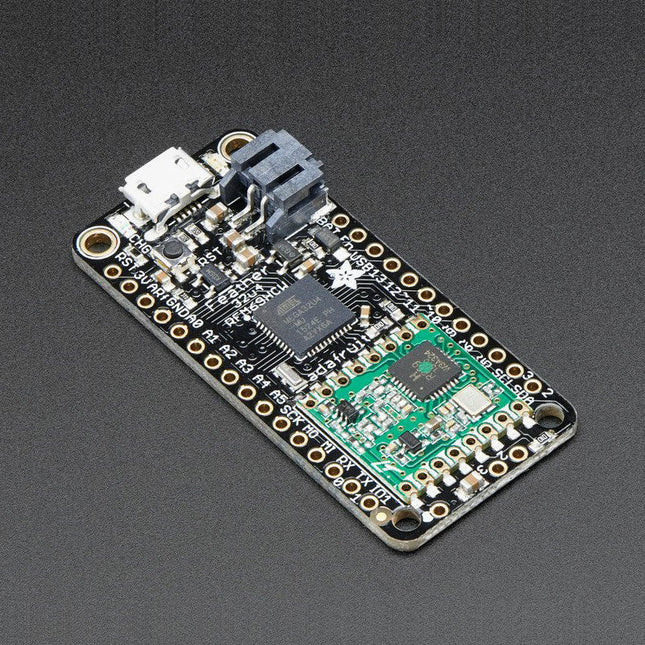
This 900 MHz radio version can be used for either 868 MHz or 915 MHz transmission/reception – the exact radio frequency is determined when you load the software since it can be tuned around dynamically.
At the Feather 32u4's heart is at ATmega32u4 clocked at 8 MHz and at 3.3 V logic. This chip has 32 K of flash and 2 K of RAM, with built in USB so not only does it have a USB-to-Serial program & debug capability built in with no need for an FTDI-like chip, it can also act like a mouse, keyboard, USB MIDI device, etc.
To make it easy to use for portable projects, we added a connector for any 3.7 V Lithium polymer batteries and built in battery charging. You don't need a battery, it will run just fine straight from the micro USB connector. But, if you do have a battery, you can take it on the go, then plug in the USB to recharge. The Feather will automatically switch over to USB power when its available. We also tied the battery thru a divider to an analog pin, so you can measure and monitor the battery voltage to detect when you need a recharge.
Features
Measures 2.0' x 0.9' x 0.28' (51 x 23 x 8 mm) without headers soldered in
Light as a (large?) feather – 5.5 grams
ATmega32u4 @ 8 MHz with 3.3 V logic/power
3.3 V regulator with 500 mA peak current output
USB native support, comes with USB bootloader and serial port debugging
You also get tons of pins – 20 GPIO pins
Hardware Serial, hardware I²C, hardware SPI support
7x PWM pins
10x analog inputs
Built in 100 mA lipoly charger with charging status indicator LED
Pin #13 red LED for general purpose blinking
Power/enable pin
4 mounting holes
Reset button
The Feather 32u4 Radio uses the extra space left over to add an RFM69HCW 868/915 MHz radio module. These radios are not good for transmitting audio or video, but they do work quite well for small data packet transmission when you ned more range than 2.4 GHz (BT, BLE, WiFi, ZigBee)
SX1231 based module with SPI interface
Packet radio with ready-to-go Arduino libraries
Uses the license-free ISM band ('European ISM' @ 868 MHz or 'American ISM' @ 915 MHz)
+13 to +20 dBm up to 100 mW Power Output Capability (power output selectable in software)
50 mA (+13 dBm) to 150 mA (+20 dBm) current draw for transmissions
Range of approx. 350 meters, depending on obstructions, frequency, antenna and power output
Create multipoint networks with individual node addresses
Encrypted packet engine with AES-128
Simple wire antenna or spot for uFL connector
Comes fully assembled and tested, with a USB bootloader that lets you quickly use it with the Arduino IDE. Headrs are also included so you can solder it in and plug into a solderless breadboard. You will need to cut and solder on a small piece of wire (any solid or stranded core is fine) in order to create your antenna.
Lipoly battery and USB cable not included.
Pico Breakout Garden Base sits underneath your Pico and lets you connect up to six of our extensive selection of Pimoroni breakouts to it. Whether it's environmental sensors so you can keep track of the temperature and humidity in your office, a whole host of little screens for important notifications and readouts, and, of course, LEDs. Scroll down for a list of breakouts that are currently compatible with our C++/MicroPython libraries!As well as a labelled landing area for your Pico, there's also a full set of broken out Pico connections, in case you need to attach even more sensors, wires, and circuitry. We've thrown in some rubber feet to keep the base nice and stable and to stop it from scratching your desk, or there are M2.5 mounting holes at the corners so that you can bolt it onto a solid surface if you prefer.The six sturdy black slots are edge connectors that connect the breakouts to the pins on your Pico. There's two slots for SPI breakouts, and four slots for I²C breakouts. Because I²C is a bus, you can use multiple I²C devices at the same time, providing they don't have the same I²C address (we've made sure that all of our breakouts have different addresses, and we print them on the back of the breakouts so they're easy to find).As well as being a handy way to add functionality to your Pico, Breakout Garden is also very useful for prototyping projects without the need for complicated wiring, soldering, or breadboards, and you can grow or change up your setup at any time.Features
Six sturdy edge-connector slots for breakouts
4x I²C slots (5 pins)
2x SPI slot (7 pins)
Landing area with female headers for Raspberry Pi Pico
0.1” pitch, 5 or 7 pin connectors
Broken-out pins
Reverse polarity protection (built into breakouts)
99% assembled – just need to stick on the feet!
Compatible with Raspberry Pi Pico
Thanks to its six sturdy slots, Breakout Garden enables the users to simply plug and play with various tiny breakout board.
Just insert one or more boards into the slots in the Breakout Garden HAT and you’re ready to go. The mini breakouts feel secure enough in the edge-connector slots and are very unlikely to fall out.
There are a number of useful pins along the top of Breakout Garden, which lets you connect other devices and integrate them into your project.
You shouldn't be worried if you insert a board the wrong way thanks to provided reverse polarity protection. It doesn't matter which slot you use for each breakout either, because the I²C address of the breakout will be recognised by the software and it'll detect them correctly in case you move them around.
Features
Six sturdy edge-connector slots for Pimoroni breakouts
0.1” pitch, 5 pin connectors
Broken-out pins (1 × 10 strip of male header included)
Standoffs (M2.5, 10 mm height) included to hold your Breakout Garden securely
Reverse polarity protection (built into breakouts)
HAT format board
Compatible with Raspberry Pi 3 B+, 3, 2, B+, A+, Zero, and Zero W
It's suggested using the included standoffs to attache Breakout Garden to your Raspberry Pi.
Software
Breakout Garden doesn't require any software of its own, but each breakout you use will need a Python library. On the Breakout Garden GitHub page you'll find an automatic installer, which will install the appropriate software for a given breakout. There are also some examples that show you what else you can do with Breakout Garden.
The MLX90640 SparkFun IR Array Breakout features a 32×24 array of thermopile sensors generating, in essence, a low resolution thermal imaging camera. With this breakout you can observe surface temperatures from a decent distance away with an accuracy of ±1.5°C (best case). This board communicates via I²C using the Qwiic system developed by Sparkfun, which makes it easier to operate the breakout. However, there are still 0.1'-spaced pins in case you favour using a breadboard.
The SparkFun Qwiic connect system is an ecosystem of I²C sensors, actuators, shields and cables that make prototyping faster and helps you avoid errors. All Qwiic-enabled boards use a common 1 mm pitch, 4-pin JST connector. This reduces the amount of required PCB space, and polarized connections help you connect everything correctly.
This specific IR Array Breakout provides a 110°×75° field of view with a temperature measurement range of -40~300°C. The MLX90640 IR Array has pull up resistors attached to the I²C bus; both can be removed by cutting the traces on the corresponding jumpers on the back of the board. Please be aware that the MLX90640 requires complex calculations by the host platform so a regular Arduino Uno (or equivalent) doesn't have enough RAM or flash to complete the complex computations required to turn the raw pixel data into temperature data. You will need a microcontroller with 20,000 bytes or more of RAM.
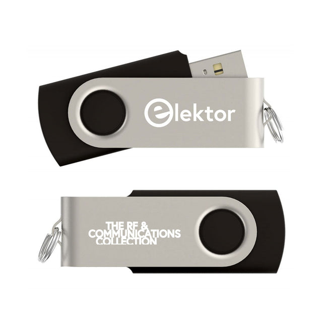
This USB Stick contains more than 300 Arduino-related articles published in Elektor Magazine. The content includes both background articles and projects on the following topics:
Software & hardware development: Tutorials on Arduino software development using Arduino IDE, Atmel Studio, Shields, and essential programming concepts.
Learning: The Microcontroller Bootcamp offers a structured approach to programming embedded systems.
Data acquisition & measurement: Projects such as a 16-bit data logger, lathe tachometer, and an AC grid analyzer for capturing and analyzing real-time signals.
Wireless communication: Learn how to implement wireless networks, create an Android interface, and communicate effectively with microcontrollers.
Robotics and automation: This covers the Arduino Nano Robot Controller, supporting boards for automation, and explores various Arduino shields to enhance functionality.
Self-build projects: Unique projects such as laser projection, Numitron clock and thermometer, ELF receiver, Theremino, and touch LED interfaces highlight creative applications.
Whether you're a beginner or an experienced maker, this collection is a valuable resource for learning, experimenting, and pushing the boundaries of Arduino technology.
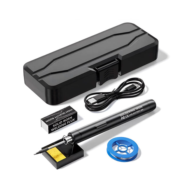
The Smart USB Soldering Iron Kit is a compact, cordless solution designed for precision and portability. Featuring intelligent three-speed temperature control (300-450°C) with an easy-to-read LED display, it heats up in just 10 seconds and melts solder in as little as 6 seconds.
The 1000 mAh rechargeable battery delivers up to 30 minutes of continuous use, making it ideal for quick repairs, electronics projects, and DIY tasks. With a plug-and-play, replaceable tip and a high-temperature-resistant insulated shell, it’s safe, user-friendly, and perfect for both beginners and professionals on the go.
Features
Three-Speed Intelligent Temperature Adjustment: Features an LED display screen with adjustable temperatures between 300-450°C (572-842°F). Easily switch between Celsius and Fahrenheit.
Integrated Plug-In Soldering Iron Tip: Plug-and-play design. The tip can be replaced by simply unscrewing it, ensuring quick and convenient operation.
Safe and Durable Design: High-temperature-resistant, insulated shell for enhanced safety during use.
Battery Capacity: Equipped with a rechargeable 1000 mAh battery that supports up to 30 minutes of continuous operation on a full charge – ideal for everyday tasks.
Efficient Performance: 8 W power with an integrated heating core for rapid heat-up. Melts tin in just 6 seconds, providing excellent thermal conductivity.
Easy to Use: After powering on via USB, set your desired temperature. The soldering iron heats up in 10 seconds. Once finished, place the tip on the stand—it cools down within 1 minute. Perfect for beginners, hobbyists, basic home repairs, and training engineers.
Cordless Innovation: This cordless soldering kit includes a built-in rechargeable lithium-ion battery, eliminating the need for cables. Versatile use for circuit board soldering, electrical repairs, jewelry making, metal crafts, computer maintenance, and DIY projects.
Specifications
Adjustable Temperature: 300-450°C (572-842°F)
Tin Melting Time: <15 seconds
Working Voltage: 5 V
Power Output: 8 W
Battery Capacity: 1000 mAh
Auto Sleep Function: Activates after 10 minutes of inactivity
Charging Time: Approx. 90 minutes
Battery Life: Up to 30 minutes continuous use
Charging Interface: USB-C
Main Material: Aluminum alloy
Dimensions: 190 x 16 mm (7.4 x 0.6")
Included
1x USB Soldering Iron
1x Soldering Tip
1x Soldering Rosin
1x Soldering Iron Holder (with Sponge)
1x USB-C Charging Cable
1x Solder Wire
1x Storage Box
Some Highlights from the contents Surround-sound decoder Compact amp Sampling rate converter Battery powered preamplifier Titan 2000 amplifier Crescendo Millennium amplifier Audio-DAC/ADC IR-S/PDFI receiver and transmitter High-End Power Amp Hi-fi Wireless Headset Paraphase Tone Control and more… Using Adobe Reader you are able to browse and search the articles on your computer, as well as print texts, circuit diagrams and PCB layouts.
This USB stick holds a selection of more than 350 articles on RF, Radio and Communication published in Elektor Magazine. The content consists of both background articles and projects with the following topics:
Basic radio-related circuits as well as more complex circuits like filters, oscillators, and amplifiers.
Design, construction, and theory of antennas for transmitting and receiving radio signals efficiently.
Design and analysis of RF circuits including filters, mixers, PLLs, and frequency synthesizers. Tools and techniques for predicting radio wave propagation paths and measuring RF signal strength.
Techniques for processing digital signals in RF systems, including modulation and demodulation methods.
Projects on radio receivers, AM, FM, SSB, CW, DRM, DAB, DAB+, Software Defined Radio, and more.
Projects on Wi-Fi, Bluetooth, LoRaWAN, and more.
You can use the article search function to locate specific content in the full text. The results are always shown as preformatted PDF documents. You can use Adobe Reader to browse articles, and you can use Adobe Reader’s integrated search functions to find instances of individual words and expressions.
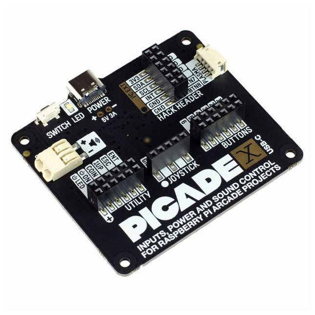
Turn your Raspberry Pi into a retro games console! Picade X HAT includes joystick and button inputs, a 3 W I²S DAC/amplifier, and soft power switch. This HAT has all the same great features as the original Picade HAT but now has no-fuss female Dupont connectors to hook up your joystick and buttons. Simply pop Picade X HAT onto your Pi, plug a USB-C power supply into the connector on the HAT (it back-powers your Pi through the GPIO, so no need for a separate power supply), wire up your controls, and install the driver! It's ideal for your own DIY arcade cabinet builds, or for interfaces that need big, colourful buttons and sound. Features I²S audio DAC with 3 W amplifier (mono) and push-fit terminals Safe power on/off system with tactile power button and LED USB-C connector for power (back-powers your Pi) 4-way digital joystick inputs 6x player button inputs 4x utility button inputs 1x soft power switch input 1x power LED output Plasma button connector Breakout pins for power, I²C, and 2 additional buttons Picade X HAT pinout Compatible with all 40-pin Raspberry Pi models The I²S DAC blends both channels of digital audio from the Raspberry Pi into a single mono output. This is then passed through a 3 W amplifier to power a connected speaker. The board also features a soft power switch that allows you turn your Pi on and off safely without risk of SD card corruption. Tap the connected button to start up, and press and hold it for 3 seconds to fully shutdown and disconnect power. Software/Installation Open a terminal and type curl https://get.pimoroni.com/picadehat | bash to run the installer. You'll need to reboot once the installation is complete, if it doesn't prompt you to do so. The software does not support Raspbian Wheezy Notes With USB-C power connected through Picade X HAT you'll need either to tap the connected power button or the button marked 'switch' on the HAT to power on your Pi.
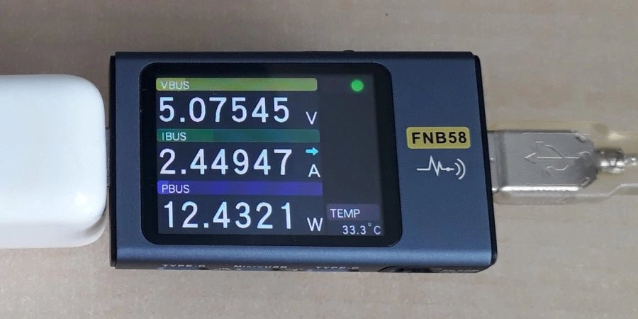
The FNIRSI FNB58 USB tester (with Bluetooth) is a comprehensive and very accurate USB voltage and current meter. It features a 2.0-inch full-color HD TFT display, built-in USB-A, micro USB and USB-C interface. With this device you can measure the power supply or power consumption of products or the charging power of cell phones and power supplies. You can also determine the fast charging protocol of chargers.
Features
USB-A and USB-C interface
2.0" HD display
Data at a glance
Wide compatibility
Ultra-precise data detection
Play with fast charging technology
Automatic protocol detection (PD2.0, 3.0, 3.1, PPS, QC2.0, 3.0, FCP, SCP, AFC, PE, DASH VOOC, SuperVOOC and more)
Simple user interface, easy to operate
4 function curve displays (real-time voltage and current curve, offline curve recording, D+/D- voltage curve, high-speed power supply ripple measurement)
Cable detection
10 groups of energy recording battery capacity calculation
PC connectivity for data logging and firmware updates
Bluetooth app for Android devices
Specifications
Voltage range
4-28 V
Current range
0-7 A
Power range
0-120 W
Load equivalent internal resistance
0-9999.9 Ω
D+/D- voltage
0-3.3 V
Capacity
0-9999.99 Ah
Power consumption
0-9999.99 Wh
Cable resistance
0-9999.9 Ω
Interfaces
micro USB, USB-A, USB-C
Dimensions
42 x 13 x 82 mm
Downloads
Manual
Firmware V0.68
,
by Jean-François Simon
Fnirsi FNB58 USB Tester (Review)
The Fnirsi FNB58 is a versatile USB tester capable of performing a wide array of voltage, current, and energy measurements, as well as supporting numerous...