MDP (Mini Digital Power System) is a system of programmable linear DC power supply based on modular design, capable of connecting different modules for use as needed. MDP-XP consists of a display control module (MDP-M01) and a digital power module (MDP-P906).
Through 2.4 GHz wireless connection, it achieves multichannel free combination at the power of 300 W per channel. MDP-XP is a high cost-effective programmable linear DC power supply, featuring indicators, stability, reliability and distinct user interface comparable with professional power supplies; it also provides programmable output, timing output, sequential control, automatic compensation and other powerful functions, so as to meet diversified testing needs.
MDP-M01 Display Control Module: equipped with a 2.8-inch TFT screen, it can display the voltage-current waveform in real time, support data statistics, and automatically pair with and control six sub-modules (digital power modules), with dual thumb wheels and 90-degree scrolling user-friendly design.
MDP-P906 Digital Power Module: high efficiency linear output, 0.25 mV ripple wave, high-speed transient response, and supporting precise fine-tuning.
Specifications (MDP-M01)
Screen size
2.8' TFT
Screen resolution
240 x 320
Power
Micro USB power input, or taking power from sub-module via dedicated power cable
Input
DC 5 V/0.3 A
Other functions
Can control up to 6 sub-modulesUpgrade formware through Micro USB
Dimensions
107 x 66 x 13.6 mm
Weight
133 g
Specifications (MDP-P906)
Input
DC 4.2-30 V/14 A (Max)QC 3.0/PD2.0, 20 V/5 A (Max)
Output
0-30 V/0-10 A, 300 W (Max)
Conversion efficiency
95%
Output resolution
10 mV/2 mA, up to 1 mV/1 mA via Display Control module
Output accuracy
0.03%+5 mV0.05%+2 mV
Adjustment rate
Load adjustment rate <±0.01%Power adjustment rate <±0.01%
Ripple and noise
<250 uVrms, 3 mVpp; 2 mArms
Transient response
<4 uS
Safety protections
Input over-voltage, under-voltage, reverse connection protection, output over-current, back-flow protection and over-temperature protection
Others
Automatically shut-down and enter micro-power modeSupport USB firmware upgrade
Dimensions
112 x 66 x 20 mm
Weight
181 g
Included
MDP-M01
1x MDP-M01 Smart Digital Monitor
1x Cable (2.5 mm jack to Micro USB)
MDP-P906
1x MDP-P906 Digital Power Supply
2x Output Cable
1x User Manual
Downloads
MDP-M01 User Manual v3.4
MDP-P906 User Manual v1.1
Firmware v1.32
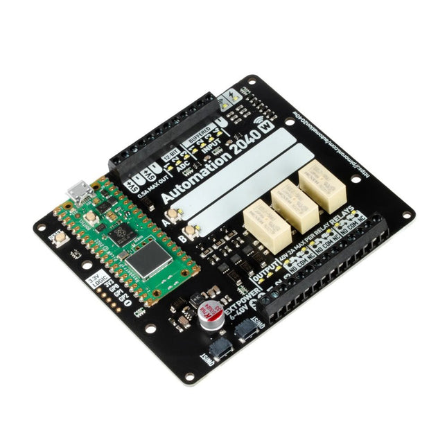
An all-in-one, Pico W powered industrial/automation controller with 2.46 GHz wireless connectivity, relays and a plethora of inputs and outputs. Compatible with 6 V to 40 V systems.
Automation 2040 W is a Pico W / RP2040 powered monitoring and automation board. It contains all the great features from the Automation HAT (relays, analog channels, powered outputs and buffered inputs) but now in a single compact board and with an extended voltage range so you can use it with more devices. Great for controlling fans, pumps, solenoids, chunky motors, electronic locks or static LED lighting (up to 40 V).
All the channels (and the buttons) have an associated indicator LED so you can see at a glance what's happening with your setup, or test your programs without having hardware connected.
Features
Raspberry Pi Pico W Aboard
Dual Arm Cortex M0+ running at up to 133 Mhz with 264 kB of SRAM
2 MB of QSPI flash supporting XiP
Powered and programmable by USB micro-B
2.4 GHz wireless
3x 12-bit ADC inputs up to 40 V
4x digital inputs up to 40 V
3x digital sourcing outputs at V+ (supply voltage)
4 A max continuous current
2 A max current at 500 Hz PWM
3x relays (NC and NO terminals)
2 A up to 24 V
1 A up to 40 V
3.5 mm screw terminals for connecting inputs, outputs and external power
2x tactile buttons with LED indicators
Reset button
2x Qw/ST connectors for attaching breakouts
M2.5 mounting holes
Fully assembled
No soldering required.
C/C++ and MicroPython libraries
Schematic
Dimensional drawing
Power
Board is compatible with 12 V, 24 V and 36 V systems
Requires supply 6-40 V
Can provide 5 V up to 0.5 A for lower voltage applications
Software
Pirate-brand MicroPython
Getting Started with Raspberry Pi Pico
MicroPython examples
MicroPython function reference
C++ examples
C++ function reference
Getting Started with Automation 2040 W
Pimoroni Pico LiPo is powered and programmable via USB-C and comes with 16 MB of QSPI (XiP) flash. With the Qwiic/STEMMA QT connector you can hook up a whole host of different sensors and breakouts, and a debug connector for if you want to do your programming using a SWD debugger. There is an on/off button and a BOOTSEL button, which can also be used as a user switch.Pimoroni Pico LiPo also has onboard LiPo/LiIon battery management – the inbuilt charging circuitry means charging your battery is as easy as plugging your Pimoroni Pico Lipo in via USB. Two indicator LEDs connected to the battery circuit keep you informed of on/off state and charging status and it's compatible with any of our LiPo, LiIon and high capacity LiPo batteries.Programmable with C++, MicroPython or CircuitPython, Pimoroni Pico LiPo is the perfect powerhouse for your portable projects.Features
Powered by RP2040
Dual ARM Cortex M0+ running at up to 133 Mhz
264 kB of SRAM
16 MB of QSPI flash supporting XiP
MCP73831 charger with 215 mA charging current (datasheet)
XB6096I2S battery protector (datasheet)
USB-C connector for power, programming, and data transfer
4 pin Qw-ST (Qwiic / STEMMA QT) connector
3 pin debug connector (JST-SH)
2-pole JST PH battery connector, with polarity marked on the board
Switch for basic input (doubles up as DFU select on boot)
Power button
Power, charging and user LED indicators
On-board 3V3 regulator (max regulator current output 600mA)
Input voltage range 3 - 5.5 V
Compatible with Raspberry Pi Pico add-ons
Measurements: approx 53 x 21 x 8 mm (L x W x H, including connectors)
Downloads
CircuitPython
Getting started with CircuitPython guide
The JOY-iT Armor Case BLOCK is a robust aluminum enclosure designed specifically for the Raspberry Pi 5. It offers excellent protection against heat and physical shocks, making it suitable for challenging environments. Its compact design ensures that it doesn't require additional space, allowing for seamless integration into existing projects.
The case includes a large heatsink to enhance cooling efficiency. Installation is straightforward, with four screws (included) securing the case to the Raspberry Pi.
Specifications
Material
CNC milled aluminum alloy
Cooling performance
Idle: ~39°CFull load: ~75°C
Special features
Large heat sink, protection against shocks and heat with the same volume as without housing
Dimensions (top side)
69 x 56 x 15,5 mm
Dimensions (bottom side)
87 x 56 x 7,5 mm
EAGLE – the “Easily Applicable Graphical Layout Editor“ is a professional-grade CAD (computer aided design) software package for the design and drafting of electronic schematics as well as the design and fabrication of printed circuit boards (PCBs).
This Advanced User Guide provides the experienced EAGLE user with insight into using some of the more advanced features of EAGLE software. It is not a guide to teach the reader the basic concepts of EAGLE, nor does it discuss the ‘how to’ of the EAGLE interface and the simpler operations and commands of the software. That is the purpose of the author’s previous title EAGLE V6 Getting Started Guide also published by Elektor.
This eBook is intended as an enduring document covering the more advanced modules, commands, and functions which make up EAGLE. It is hoped that this eBook will provide a quick, succinct reference to assist with more complex applications and uses of EAGLE – an ‘EAGLE User’s Companion’, if you like.
Complementing the EAGLE Advanced User Guide, the EAGLE User Language manual is included in this eBook in unabridged form, reproduced with permission of CadSoft GmbH.
At the time of writing, the material in this eBook covers version 7 of the EAGLE software suite.
This book is all about building your own DIY home control system. It presents two innovative ways to assemble such a system: By recycling old PC hardware – possibly extending the life of an old PC, or by using Raspberry Pi. In both cases, the main system outlined in this book will consist of a computer platform, a wireless mains outlet, a controller and a USB webcam – All linked together by Linux.
By using the Raspberry Pi in conjunction with Arduino (used as an advanced I/O system board), it is possible to construct a small, compact, embedded control system offering enhanced capacity for USB integration, webcams, thermal monitoring and communication with the outside world.
The experience required to undertake the projects within this book are minimal exposure to PC hardware and software, the ability to surf the internet, burn a CD-ROM and assemble a small PCB.
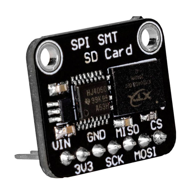
This flash memory allows you to store and read data externally via the SPI interface of your microcontroller. The control of the module is exactly the same as with a conventional SD card and is therefore particularly simple. The module is especially suitable for mobile setups, where normal SD cards could slip out of the SD card slot. Specifications Special feature 3 V and 5 V operation due to the integrated voltage converter Supply voltage Vcc 3-5 V Logic level Vcc Interface SPI Memory size 512 MB Clock frequency Up to 50 MHz Dimensions 18 x 22 x 12 mm Weight 3 g
The LILYGO T-Panel S3 is a versatile development board designed for IoT applications, featuring a 4-inch IPS LCD with a 480x480 resolution.
Powered by the ESP32-S3 microcontroller, it offers 2.4 GHz Wi-Fi and Bluetooth 5 (LE) connectivity, with 16 MB of flash memory and 8 MB of PSRAM. The board supports development environments such as Arduino, PlatformIO-IDE, and MicroPython. Notably, it includes a capacitive touch interface, enhancing user interaction capabilities. Onboard functions comprise Boot (IO00), Reset, and two additional keys, providing flexibility for various applications. This combination of features makes the T-Panel S3 suitable for a wide range of IoT projects and smart device control interfaces.
Specifications
MCU1
ESP32-S3
Flash
16 MB
PSRAM
8 MB
Wireless Connectivity
2.4 GHz Wi-Fi + Bluetooth 5 (LE)
MCU2
ESP32-H2
Flash
4 MB
Wireless Connectivity
IEEE 802.15.4 + Bluetooth 5 (LE)
Developing
Arduino, PlatformIO-IDE, Micropython
Display
4.0" 480x480 IPS ST7701S LCD
Resolution
480 x 480 (RGB)
Interface
SPI + RGB
Compatibility library
Arduino_ GFX, LVGL
Onboard functions
QWiiCx2 + TF Card + AntennaESP32 4x Button= S3(Boot + RST) + H2(Boot + RST)
Transceiver Module
RS485
Using bus communication protocol
UART
Included
1x T-Panel S3
1x Female pin (2x 8x1.27)
Downloads
GitHub
The Arduino Nano 33 BLE Rev2 stands at the forefront of innovation, leveraging the advanced capabilities of the nRF52840 microcontroller. This 32-bit Arm Cortex-M4 CPU, operating at an impressive 64 MHz, empowers developers for a wide range of projects. The added compatibility with MicroPython enhances the board's flexibility, making it accessible to a broader community of developers.
The standout feature of this development board is its Bluetooth Low Energy (Bluetooth LE) capability, enabling effortless communication with other Bluetooth LE-enabled devices. This opens up a realm of possibilities for creators, allowing them to seamlessly share data and integrate their projects with a wide array of connected technologies.
Designed with versatility in mind, the Nano 33 BLE Rev2 is equipped with a built-in 9-axis Inertial Measurement Unit (IMU). This IMU is a game-changer, offering precise measurements of position, direction, and acceleration. Whether you're developing wearables or devices that demand real-time motion tracking, the onboard IMU ensures unparalleled accuracy and reliability.
In essence, the Nano 33 BLE Rev2 strikes the perfect balance between size and features, making it the ultimate choice for crafting wearable devices seamlessly connected to your smartphone. Whether you're a seasoned developer or a hobbyist embarking on a new adventure in connected technology, this development board opens up a world of possibilities for innovation and creativity. Elevate your projects with the power and flexibility of the Nano 33 BLE Rev2.
Specifications
Microcontroller
nRF52840
USB connector
Micro USB
Pins
Built-in LED Pins
13
Digital I/O Pins
14
Analog Input Pins
8
PWM Pins
All digital pins (4 at once)
External interrupts
All digital pins
Connectivity
Bluetooth
u-blox NINA-B306
Sensors
IMU
BMI270 (3-axis accelerometer + 3-axis gyroscope) + BMM150 (3-axis Magnetometer)
Communication
UART
RX/TX
I²C
A4 (SDA), A5 (SCL)
SPI
D11 (COPI), D12 (CIPO), D13 (SCK). Use any GPIO for Chip Select (CS)
Power
I/O Voltage
3.3 V
Input Voltage (nominal)
5-18 V
DC Current per I/O Pin
10 mA
Clock Speed
Processor
nRF52840 64 MHz
Memory
nRF52840
256 KB SRAM, 1 MB flash
Dimensions
18 x 45 mm
Downloads
Datasheet
Schematics
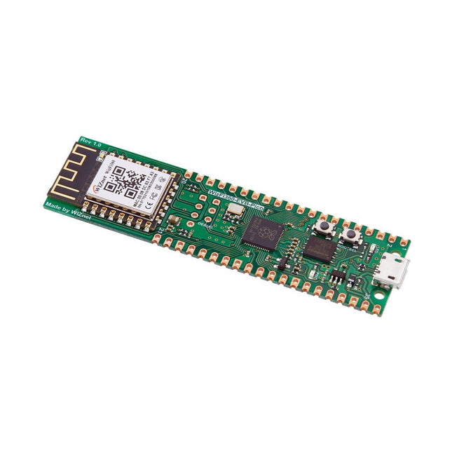
Raspberry Pi Pico EVB combined with the WizFi360-PAWizFi360-EVB-Pico is based on Raspberry Pi RP2040 and adds Wi-Fi connectivity using WizFi360. It is pin-compatible with Raspberry Pi Pico board and can be used for IoT Solution development.Specifications
RP2040 microcontroller with 2 MByte Flash
Dual-core cortex M0+ at up to 133 MHz
264 kByte multi-bank high performance SRAM
External Quad-SPI Flash with eXecute In Place (XIP)
Includes WizFi360-PA
Supports Hardwired Internet Protocols: TCP, UDP, WOL over UDP, ICMP, IGMPv1/v2, IPv4, ARP, PPPoE
WiFi 2.4G, 802.11 b/g/n
Support Station / SoftAP / SoftAP+Station operation modes
Support “Data pass-through” and “AT command data transfer” mode
Support serial AT command configuration
Support TCP Server / TCP Client / UDP operating mode
Support configuration of operating channel 0 ~ 13
Support auto 20 MHz / 40 MHz bandwidth
Support WPA_PSK / WPA2_PSK encryption
Support built-in unique MAC address and user configurable
Industrial grade (operating temperature range: -40°C ~ 85°C)
CE, FCC certification
Includes 16 Mbit Flash Memory
Micro-USB B port for power and data (and for reprogramming the Flash)
40 pin 21×51 ‘DIP’ style 1mm thick PCB with 0.1' through-hole pins also with edge castellations
3-pin ARM Serial Wire Debug (SWD) port
Built-in LDO
DownloadsDocumentation
This carrier board combines a 2.4" TFT display, six addressable LEDs, onboard voltage regulator, a 6-pin IO connector, and microSD slot with the M.2 pin connector slot so that it can be used with compatible processor boards in our MicroMod ecosystem. We've also populated this carrier board with Atmel's ATtiny84 with 8kb of programmable flash. This little guy is preprogrammed to communicate with the processor over I²C to read button presses.
Features
M.2 MicroMod Connector
240 x 320 pixel, 2.4" TFT display
6 Addressable APA102 LEDs
Magnetic Buzzer
USB-C Connector
3.3 V 1 A Voltage Regulator
Qwiic Connector
Boot/Reset Buttons
RTC Backup Battery & Charge Circuit
microSD
Phillips #0 M2.5 x 3 mm screw included
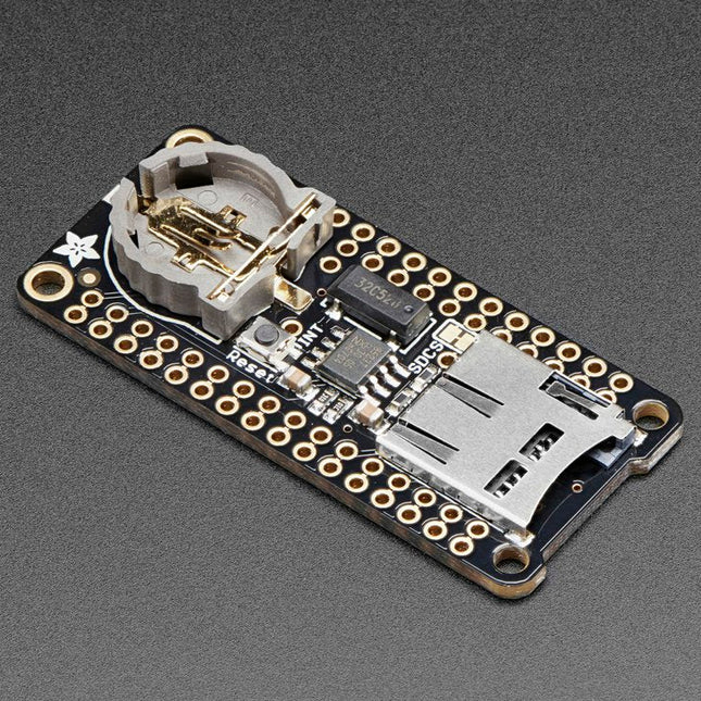
This FeatherWing will make it easy to add data logging to any Feather Board you might have. You get both an I²C real-time clock (PCF8523) with 32 KHz crystal and battery backup, and a microSD socket that connects to the SPI port pins (+ extra pin for CS). Note: FeatherWing doesn't come with a microSD card. A CR1220 coin cell is required to use the RTC battery-backup capabilities. If you're not using the RTC part of the FeatherWing, a battery is not required. To talk to the microSD card socket Arduino's default SD library is recommended. Some light soldering is required to attach the headers onto the Wing. Pinouts Power pins On the bottom row, the 3.3 V (second from left) and GND (fourth from left) pin are used to power the SD card and RTC (to take a load off the coin cell battery when main power is available) RTC & I²C Pins In the top right, SDA (rightmost) and SCL (to the left of SDA) are used to talk to the RTC chip.
SCL - I²C clock pin to connect to your microcontroller's I2C clock line. This pin has a 10 kΩ pull-up resistor to 3.3 V
SDA - I²C data pin to connect to your microcontroller's I2C data line. This pin has a 10 kΩ pull-up resistor to 3.3 V There's also a breakout for INT which is the output pin from the RTC. It can be used as an interrupt output or it could also be used to generate a square wave. Note that this pin is an open drain - you must enable the internal pull-up on whatever digital pin it is connected to. SD & SPI Pins Starting from the left you've got SPI Clock (SCK) - output from feather to wing SPI Master Out Slave In (MOSI) - output from feather to wing SPI Master In Slave Out (MISO) - input from wing to feather These pins are in the same location on every Feather. They are used for communicating with the SD card. When the SD card is not inserted, these pins are completely free. MISO is tri-stated whenever the SD CS (chip select) pin is pulled high
The Mr. Pulsar Violent Turbo Fan X3 Pro delivers powerful airflow with its impressive 140,000 RPM motor, offering exceptional performance in a compact, portable design.
Featuring an 8,000 mAh battery for extended wireless operation, adjustable airflow speeds, and weighing just 277 grams, it's perfect for quick tasks like computer cleaning, drying pets, inflating air mattresses, removing dust, or even blowing snow from your car.
Specifications
Motor speed
140,000 RPM
Battery
8,000 mAh Lithium battery
Dimensions
160 x 60 x 90 mm
Weight
277 g
Included
1x Mr. Pulsar Violent Turbo Fan X3 Pro
1x Short nozzle
1x Storage bag
1x USB-C cable
Elektor GREEN and GOLD members can download their digital edition here.
Not a member yet? Click here.
CaptureCountAn Object Detector and Counter on the Raspberry Pi 5
Voltage Reference With Arduino Pro MiniLinearize and Calibrate Your Analog Inputs
FPGAs for BeginnersThe Path From MCU to FPGA Programming
Update: STM32 Wireless Innovation Design Contest 2024
Bluetooth LE With MAUIControl Apps for Android & Co.
Port-Expanding Breakout BoardIncrease the Number of I/Os on Your Dev Board
AI SpecialistMachine Learning with the Jetson Nano
2024: An AI OdysseyFirst Forays Into TensorFlow
262,144 Ways to Play The Game of LifeA Reader’s Project in Brief
From Life’s ExperienceThe Chinese Dragon
Get Your (Brushed DC) Motor Running!Sample Projects from the Elektor Motor Control Development Bundle
ESP32-RS-232 AdapterA Wireless Link for Classic Test Equipment
Starting Out in Electronics……More About Opamps
ESP Library Recommendations
Piezoelectric DevicesPeculiar Parts, the Series
A Smart Object CounterImage Recognition Made Easy with Edge Impulse
Resolve Your Trickiest Embedded Development Challenges
ESP32 TerminalA Handheld Device with a Touch-Capable Display
Getting Started With the Zephyr RTOSAs Powerful as It Is Hard to Master
Award-Winning EthicsA Dialog with CTO Alexander Gerfer of Würth Elektronik eiSos on Enabling Innovation and Mindful Behavior
Err-lectronicsCorrections, Updates, and Readers’ Letters
Infographics: Embedded and AI
Square Wave Generation BenchmarksExploring ESP32, Pico, and Other Microcontrollers
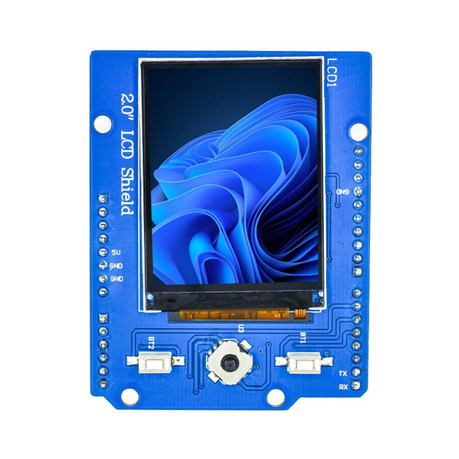
The Ardi Display Shield features a vibrant 2" IPS screen with a resolution of 240 x 320 pixels, providing sharp and crisp visuals for your projects. Whether you're working on a small-scale project or a complex prototype, this display shield ensures clear and vibrant display output.
With 2 programmable buttons, you have the flexibility to create interactive experiences and user-friendly interfaces. Customize the buttons to trigger specific actions or navigate through menus effortlessly.
The possibilities are endless, limited only by your imagination. In addition to the programmable buttons, the Ardi Display Shield also includes a 5-way joystick for intuitive control. With the joystick's SPI interface, you can easily navigate menus, scroll through options, and control various aspects of your Arduino project with precision and ease.
Designed with compatibility and ease of use in mind, the Ardi Display Shield seamlessly integrates with the Arduino Uno board. Simply connect it to your Arduino Uno and unlock a world of possibilities for visual feedback, user interaction, and data visualization.
Features
Onboard 2.0" TFT Display
Compatible with 3.3 V/5 V MCU, Selection provided
Onboard 5-Way Joystick allows better control-related projects
Two programmable Buttons to add additional functionality to project
Mounts directly onto ArdiPi, Ardi32 or other Arduino compatible boards
Specifications
Display resolution: 240x320 pixels
Pixel Pitch: 0.1275 x 0.1275 mm
Active Area: 30.6 x 40.8 mm
Module Size: 34.6 x 47.8 x 2.05 mm
SPI Interface
Display Colors: 65K colors
Drive IC: ST7789V2
Viewing Direction: All-view the best image
Pico Cube is a 4x4x4 LED cube HAT for Raspberry Pi Pico with 5 VDC operating voltage. Pico cube, a monochromatic Green with 64 LEDs, is a fun way to learn programming. It is designed to perform incandescent operations with low energy consumptions, robust outlook, and easy installation that make people/kids/users learn the effects of LED lights with a different pattern of colors via the combination of software and hardware i.e. Raspberry Pi Pico.
Features
Standard 40 Pins Raspberry Pi Pico Header
GPIO Based Communication
64 High-Intensity Monochromatic LEDs
Individual LED access
Each Layer Access
Specifications
Operating Voltage: 5 V
Color: Green
Communication: GPIO
LEDs: 64
Included
1x Pico Cube Base PCB
4x Layer PCB
8x Pillar PCB
2x Male Berg (1 x 20)
2x Female Berg (1 x 20)
70 LEDs
Note: Raspberry Pi Pico is not included.
Downloads
GitHub
Wiki
The Eurorack Stripboard is the most convenient way to build a simple DIY Eurorack synthesizer module. It works like a standard protoboard, but with specific additions for the Eurorack format. You can also use the Stripboard with the 4HP Front Panel.
You can place up to 5 potentiometers or 5 jack connectors on the dedicated locations. The potentiometers can be any of 9 or 16 mm types, Alpha PKN160 for example. The Jack connectors are Cliff S6/BB mono style.
With the Eurorack power supply interface, it's extremely easy to connect either a 16-pin or a 10-pin Eurorack power connector.
The clear and detailed silkscreen labels indicate where the different voltages are located on the PCB. You can also add 2 filtering capacitors and 2 protection diodes.
How to connect jacks and potentiometers
The jack connectors are Cliff CL1384. They use the strips A, B, D and E.
A and B are switched open when the male jack connector is inserted. D and E are the contacts to the male connector.
E is Tip (the signal)
and D is Ring (usually the 0V reference, often designated as “ground”).
Note that Cliff jacks are insulated from the panel.
The potentiometers are 9 mm (2.5 mm pin pitch) or 16 mm (5 mm pin pitch). Alpha 9 mm are a good choice. They align pretty nicely with Cliff jacks on the front panel. They connect to strips B, C and D.
B is Counter Clock Wise pole.
D is Clock Wise pole.
and C is Wiper pole.
Dimensions
The PCB is 100 mm high and 50 mm wide. Thus, the depth for the Eurorack module will be 50 mm behind the panel.
Downloads
Documentation
DIY Layout Creator
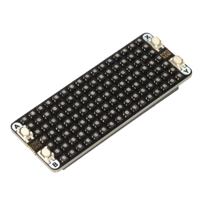
The Unicorn Pack fits nicely on the back of your Pico - with a tidy 7x16 matrix (that's 112 RGB LEDs!) it's surely the fanciest backpack going. The four tactile buttons can be used to switch between modes, as controls for simple games, or adjusting brightness. It's possible to control the colour and brightness of each LED individually so you can use it to display animations, text, simple images, and more. Make a mini photo FX lamp, a smart status light for Zoom, use it to display colourful scrolling messages on your fridge, or just enjoy some pretty animations. Features 16x7 matrix of RGB LEDs (112 total) Individual colour/brightness control of each LED 4 x tactile buttons Pre-soldered female headers for attaching to Pico Compatible with Raspberry Pi Pico. Fully assembled No soldering required (as long as your Pico has header pins attached). Dimensions: approx 62mm x 25mm x 10mm (L x W x H, including headers and buttons) C/C++ and MicroPython libraries
The Raspberry Pi A+ Case has been designed to fit both the Pi 3 Model A+ and the Pi 1 Model A+. The high-quality ABS construction consists of two parts. The base features cut-outs to allow access to the microSD Card and the the HDMI, audio/video and USB ports, as well as the power connector.
The Qwiic Mux also has eight configurable addresses of its own, allowing for up to 64 I²C buses on a connection. To make it even easier to use this multiplexer, all communication is enacted exclusively via I²C, utilizing our handy Qwiic system. The Qwiic Mux also allows you to change the last three bits of the address byte, allowing for eight jumper selectable addresses if you happen to need to put more than one Qwiic Mux Breakout on the same I²C port. The address can be changed by adding solder to any of the three ADR jumpers. Each SparkFun Qwiic Mux Breakout operates between 1.65 V and 5.5 V, making it ideal for all of the Qwiic boards we produce in house.
This version of the Micro OLED Breakout is exactly the size of its non-Qwiic sibling, featuring a screen that is 64 pixels wide and 48 pixels tall and measuring 0.66' across. But it has also been equipped with two Qwiic connectors, making it ideal for I²C operations. We've also added two mounting holes and a convenient Qwiic cable holder incorporated into a detachable tab on the board that can be easily removed thanks to a v-scored edge. We've even made sure to include an I²C pull-up jumper and ADDR jumper on the back of the board, so if you have your own I²C pull-ups or need to change the I2C address of the board! Features Qwiic-Connector Enabled Operating Voltage: 3.3V Operating Current: 10mA (20mA max) Screen Size: 64x48 pixels (0.66' Across) Monochrome Blue-on-Black I²C Interface
Whether you are an electronics enthusiast or engineering professional, this book provides the reader with an introduction to the use of the CadSoft’s EAGLE PCB design software package.
EAGLE is a user-friendly, powerful and affordable software package for the efficient design of printed circuit boards. It offers the same power and functionality to all users, at a smaller cost than its competitors. A free version of EAGLE is available to enthusiasts for their own use.
EAGLE can be used on the main computing platforms including: Microsoft Windows (XP, Vista or Windows 7); Linux (based on kernel 2.6 or above) and Apple Mac OS X (Version 10.6 or higher). Any hardware that supports these software platforms will run the EAGLE application.
The book is intended for anyone who wants an introduction to the capabilities of EAGLE. The reader may be a novice at PCB design or a professional wanting to learn about EAGLE, with the intention of migrating from another CAD package.
This book will quickly allow you to:
obtain an overview of the main modules of EAGLE: the schematic editor; layout editor and autorouter in one single interface;
learn to use some of the basic commands in the schematic and layout editor modules of EAGLE;
apply your knowledge of EAGLE commands to a small project;
learn more about some of the advanced concepts of EAGLE and its capabilities;
understand how EAGLE relates to the stages of PCB manufacture;
create a complete project, from design through to PCB fabrication. The project discussed in the book is a popular, proven design from the engineering team at Elektor.
After reading this book while practicing some of the examples, and completing the projects, the reader should feel confident about taking on more challenging endeavors.
Learn to interface and program hardware devices in a wide range of useful applications, using ARM7 microcontrollers and the C programming language. Examples covered in full detail include a simple LED to a multi-megabyte SD card running the FAT file system.
Features of this book
Build prototype circuits on breadboard or Veroboard and interface to ARM microcontrollers.
A 32-bit ARM7 microcontroller is used in interfacing and software examples.
Interfacing principles apply to other ARM microcontrollers and other non-ARM microcontrollers as well.
Example programs are written in the C programming language.
Use only free or open source software.
Download and install all programming tools from the Internet.
Template project files are provided for easy project creation.
Hardware
Interface to LEDs, transistors, optocouplers, relays, solenoids, switches, keypads, LCD displays, seven segment displays, DC motors, stepper motors, external analogue signals using the ADC, RS232, RS-485, TWI, USB, SPI and SD memory cards.
Software
Once hardware has been interfaced to a microcontroller, software must be written to control the hardware. You will learn how to write programs to operate externally interfaced hardware devices, use timers and interrupts. Also learn how to port FAT file system code for use with an SD memory card, program the PWM to produce an audio sine wave, program the PWM to speed control a DC motor and more.
A chapter on more advanced ARM microcontrollers is included with an overview of some of the newest ARM microcontrollers and their features.