
Bestsellers
-
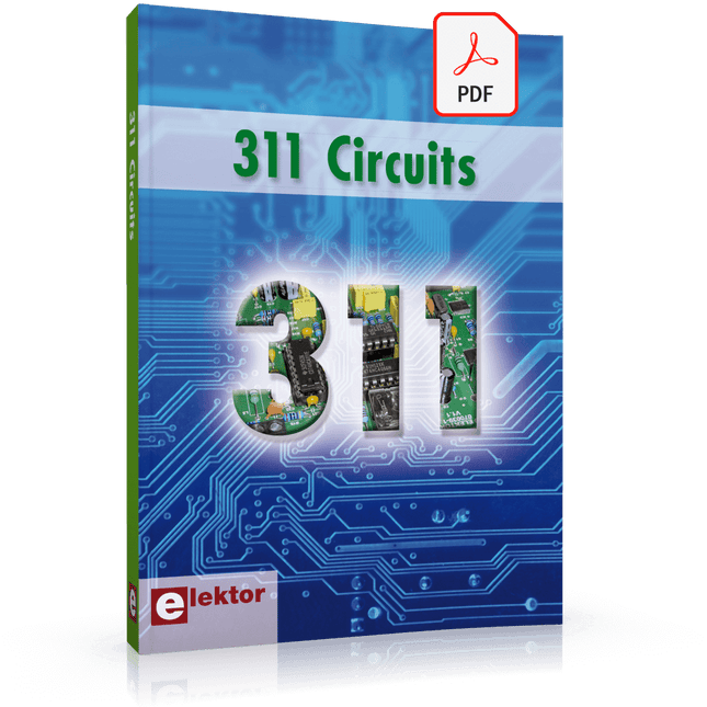
Elektor Digital 311 Circuits (E-book)
311 Circuits is the twelfth book in Elektor’s celebrated ‘300’ series. An immense source of inspiration for all electronics enthusiasts and professionals, this book deserves a place not far from the workbench. This book contains circuits, design ideas, tips and tricks from all areas of electronics: audio & video, computers & microcontrollers, radio, hobby & modelling, home & garden, power supplies & batteries, test & measurement, software, not forgetting a section ‘miscellaneous’ for everything that doesn’t fit in one of the other categories. 311 Circuits presents complete solutions for numerous problems, as well as starting points for your own creations. 311 Circuits has been compiled from the 2009, 2010 and 2011 ‘Summer Circuits’ double editions of Elektor magazine. The book is mostly based on readers’ contributions, supplemented by circuits engineered and developed in the Elektor Labs.
€ 29,95
Members: € 26,96
-
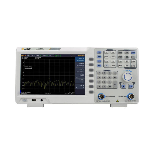
OWON OWON XSA815-TG Spectrum Analyzer (9 kHz – 1.5 GHz)
The OWON XSA815-TG (9 kHz-1.5 GHz) is a cost effective spectrum analyzer with tracking generator included and a frequency resolutions of 1 Hz. Features Frequency Range from 9 kHz to 1.500009 GHz 9-inch display 9 kHz to 1 MHz -95 dBm Displayed Average Noise Level, 1 MHz to 500 MHz 140 dBm (Typical), <-130 dBm Phase Noise -10 kHz <-80 dBc/Hz 100 kHz <-100 dBc/Hz 1 MHz <-115 dBc/Hz Resolution Bandwidth (-3 dB): 1 Hz to 1 MHz, in 1-3-5-10 sequence Tracking Generator Kit: 100 kHz to 1.500009 GHz Specifications Frequency Range 9 kHz to 500.009 MHz Frequency Resolution 1 Hz Frequency Span 9 kHz to 1.500009 GHz Span Range 0 Hz, 100 Hz to max frequency of instrument Span Uncertainty ±span / (sweep points-1) SSB Phase Noise (20°C to 30°C, fc=1 GHz) Carrier Offset 10 kHz <-80 dBc/Hz | 100 kHz <-100 dBc/Hz | 1 MHz <-115 dBc/Hz Resolution Bandwidth (-3 dB) 1 Hz to 1 MHz, in 1-3-5-10 sequence RBW Accuracy <5% typical Resolution Filter Shape Factor (60 dB: 3 dB) <5 typical Video Bandwidth (-3 dB) 10 Hz to 1 MHz, in 1-3-5-10 sequence Amplitude measurement range DANL to +10 dBm, 100 kHz to 10 MHz, Preamp Off DANL to +20 dBm, 10 MHz to 1.5 GHz, Preamp Off Reference Level -80 dBm to +30 dBm, 0.01dB by step Preamp 20 dB, nominal, 100 kHz to 1.5 GHz Input Attenuator 0 to 40 dB, 1 dB by step Display Average Noise Level Input attenuation = 0 dB, RBW = VBW = 100 Hz, sample detector, trace average ≥ 50, 20°C to 30°C, input impedance = 50 Ω) Preamp Off 9 kHz to 1 MHz -95 dBm (Typical), <-88 dBm Preamp Off 1 MHz to 500 MHz -140 dBm (Typical), <-130 dBm Preamp On 100 kHz to 1 MHz -135 dBm (Typical), <-128 dBm Preamp On 1 MHz to 500 MHz -160 dBm (Typical),<-150 dBm Tracking Generator (optional) Frequency Range 100 kHz to 1.500009 GHz Output power level range -40 dBm to 0 dBm Output level resolution 1 dB Output flatness Relative to 50 MHz | ±3 dB Tracking generator spurious Harmonic spurious -30 dBc (Tracking generator output power -10 dBm) Non-harmonic spurious -40 dBc (Tracking generator output power -10 dBm) Tracking generator to input terminal isolation -60 dB (Tracking generator output power 0 dBm) Tracking generator to input terminal isolation -60 dB (Tracking generator output power 0 dBm) Tracking generator to input terminal isolation -60 dB (Tracking generator output power 0 dBm) Dimensions 375 x 185 x 120 mm Weight 3.7 kg Included 1x XSA815-TG 1x 220 V AC power cord 1x USB Cable 1x Quickstart guide Downloads Quick Guide Specifications
€ 907,50
-
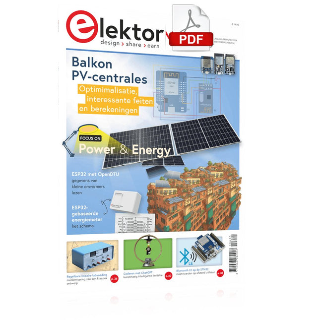
Elektor Digital Elektor Januari/Februari 2024 (PDF)
Elektor GREEN en GOLD leden kunnen deze uitgave hier downloaden. Nog geen lid? Klik hier om een lidmaatschap af te sluiten. Project-update: ESP32-gebaseerde energiemeterwe gaan verder met het prototype Optimalisatie van balkon PV-centralesoverwegingen, interessante feiten en berekeningen ESP32 met OpenDTU voor balkoncentralesgegevens van kleine omvormers via MCU’s uitlezen Regelbare lineaire labvoeding0...50 V / 0...2 A + dubbele symmetrische voeding Energieopslag – vandaag en morgeneen vraaggesprek met Simon Engelke 2024: een AI-odysseehet houdt nog lang niet op Bluetooth LE op de STM32meetwaarden op afstand uitlezen Mensvriendelijk slim keuken-voorraadsysteem MAUI: programmeren voor PC, tablet en smartphonehet nieuwe framework in theorie en praktijk ChatMagLevkunstmatig intelligente levitatie Eenvoudige PV-regelaarbouw je eerste, volledig functionele PV-energiebeheersysteem Koude-kathode-buizenvreemde onderdelen Uit het leven gegrepennostalgie Alle begin......bekijkt de FET CAN-bus voor de Arduino UNO R4: een tutorialtwee UNO R4’s nemen de bus! Elektor infographicvoeding en energie Vergelijking van vermogensdichtheid en vermogensefficiëntie Aluminium elektrolytische condensatorenstoringspotentieel in audiotechnologie USB testen en metenmet de Fnirsi FNB58 De Pixel Pump pick&place-tooleenvoudiger handmatige assemblage van SMT-printen Oost West Lab Bestnog niet zo lang geleden, in een land heel ver van hier... “In de wereld van ethiek in elektronica kunnen zelfs kleine stappen een aanzienlijke invloed hebben.” Ethiek in elektronicade OECD Guidelines en het Lieferkettensorgfaltspflichtengesetz Chadèche: slimme NiMH-(ont)laderlezersproject in het kort Project 2.0correcties, updates en brieven van lezers
€ 9,95
-
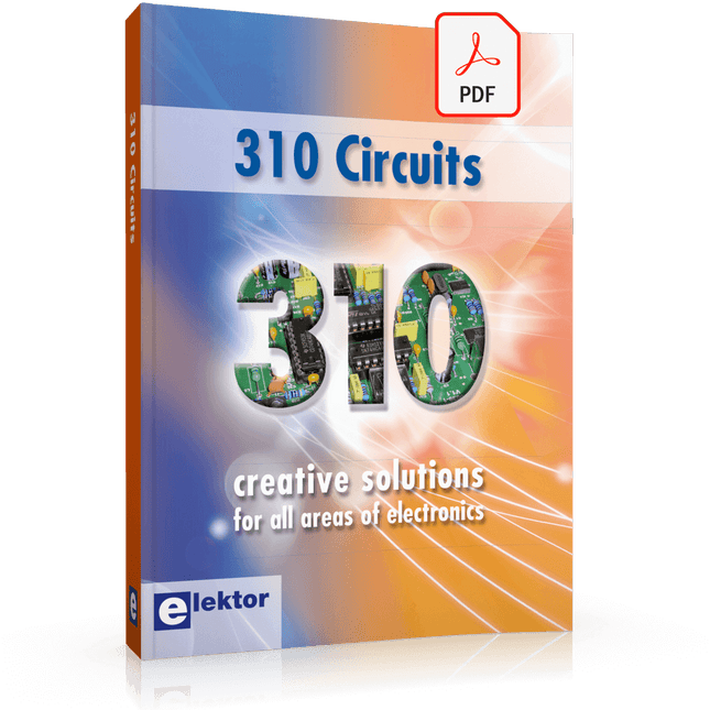
Elektor Digital 310 Circuits (E-book)
310 Circuits – is the 11th volume in Elektor’s renowned ‘Three Hundred’ series. 310 circuits, tips and design ideas in one book form a treasure trove for every area of electronics: audio and video, hobby and modelling, RF techniques, home and garden, test and measurement, microcontrollers, computer hardware and software, power supplies and chargers – plus of course everything else that does not seem to belong in any of these categories. 310 Circuits – contains many complete solutions as well as useful starting points for your own projects. Both categories and anything in between represent a veritable fountain of inspiration for cultivating your own ideas and learning about electronics. 310 Circuits – is a compilation of articles from ‘Summer Circuits’ editions for the years 2006, 2007 and 2008. ‘Summer Circuits’ covers the publication months July and August of Elektor magazine. 310 Circuits – is a must-have book for every creative electronics enthusiast, be it professional, enthusiast or student. 310 Circuits – for the first time has a section exclusively on robots and robotics.
€ 29,95
Members: € 26,96
-

Velleman Whadda Electronic Dice
This electronic dice with 7 red LEDs rolls when the push button is released and works with a 9 V battery (not included). Downloads Manual
€ 6,50
-

Electron Plus Electron Plus SPA100 Source Picoammeter
This highly sensitive source picoammeter is designed for measuring and logging very small currents down to the pA range – making it an ideal instrument for scientific and research applications, including physics, materials science and electron microscopy. Full-featured at an affordable price, the SPA100 combines sensitivity, accuracy and stability to allow users to measure low currents with high precision as well as conveniently source bias voltages for experimentation. SPA100 also doubles as an ultra-high resistance meter, measuring accurately into the teraohm range. The SPA100 connects to PC via USB and utilises the complimentary software SPA – enabling users to easily measure, graph and capture readings with timestamps and measurement stability information. Features Input: ±2 mA to ±200 pA in 8 ranges Accuracy and Resolution (2 Hz): ±2 mA range: ±0.1%, resolution <20 nA ±200 uA range: ±0.1%, resolution <2 nA ±20 uA range: ±0.2%, resolution <200 pA ±2 uA range: ±0.2%, resolution <20 pA ±200 nA range: ±0.5%, resolution <2 pA ±20 nA range: ±0.5%, resolution <200 fA ±2 nA range: ±1.0%, resolution <20 fA ±200 pA range: ±1.5%, resolution <2 fA Sample rate: 2 Hz (18 bit) or 10 Hz (16 bit) Adjustable filter: 1 sample to 64 samples Output voltage: -40 V to +40 V (in 1 V increments), output resistance 2.7 Kohms Resistance Measurement: ~1 Kohms to 40 Tohms (e.g 40 V source, 1 pA measure) Accuracy: >±0.5% 1 Mohm to 1 Tohm Powered via USB 2.0 (instrument uses up to 0.3 A when in-use) Included 1x SPA100 Source Picoammeter 1x USB cable Downloads Manual Software
€ 264,99
-

Sensepeek Sensepeek 6024 SQ500 (500 MHz handsfree Oscilloscope Probe)
The SQ series of handsfree probes from Sensepeek have a lower point of gravity making them even more stable compared with the original SP series of handsfree probes. All probes in the SQ series are also insulated and can be used handheld as any traditional probe but their full potential is used when measuring handsfree. The SQ series of oscilloscope probes also includes more ground options, have probe tip protection, longer cable and support for oscilloscopes with automatic scaling (10:1). All the loved features of handsfree measurement, exchangeable fine pitch spring tipped test needle, color-coded cable holders and the minimalistic design is maintained to make traditional sized and handheld probes obsolete. Both length and weight of the SQ probes are perfectly balanced to be used with PCBite PCB holders and base plate which is a must for handsfree function. Features Passive 10:1 probe with support for oscilloscopes with automatic scaling Spring-loaded test needle for fine pitch measurements Multiple ground options Color coded cable holders Probe tip protection Insulated, can be used handheld Improved probe holder for handsfree measurement when used with PCBite PCB holders Included 1x SQ500 500 MHz probe with spring tipped test needle 1x SQ probe holder for handsfree measurement 1x Testhook with detachable cables (5 cm & 10 cm) for convenient ground connection 1x Alligator cable for convenient ground connection 1x Standard ground spring, for handheld measurements at rated bandwidth 1x Unique ground spring, for total handsfree measurements at rated bandwidth 1x Set of color coded cable holders (4 colors) 1x Probe tip protection 1x Extra test needle Downloads User Guide SQXX0 Rev1.1
€ 131,89
-
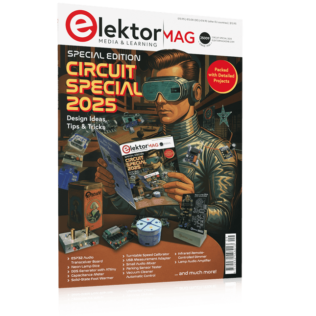
Elektor Circuit Special 2025 (EN)
Elektor GREEN and GOLD members can download their digital edition here. Not a member yet? Click here. USB Measurement AdapterTesting Current and Signal Quality of USB Ports 4...20 mA Current Output for Arduino UnoA Reliable, EMI-Insensitive Current Loop Interface Vacuum Cleaner Automatic ControlKeep Your Tools’ Work Area Clean DDS Generator with ATtiny Opamp-Tester V2New PCB – Now Also Suitable for SMDs 550-mW “Lamp” Audio AmplifierGet the Warm Sound of Vacuum Tubes With Ease Fuse GuardMonitoring a Fuse with a Flashing LED HQ RIAA PreamplifierGet the Most Out of Your Vinyl Records! Turntable Speed CalibratorAn Arduino-Based 100–120 Hz Strobe Light Generator Elektor Classics: video buffer/repeater Infrared Remote-Controlled DimmerControl Your Halogen or LED Floor Lamp Effortlessly and With Style How to Use switch…case on Strings in C++/Arduino IDE Magnet FinderWith a Simple Hall-Effect Sensor Raspberry Pi Smart Power ButtonA Solution for Raspberry Pi Up to Model 4 Essential Maker TipsProfessional Insights for Everyday Making Practical Projects with the 555 TimerDC Motor Control and Fast Reaction Challenges Basic AC-Load-On MonitorSave Energy with a Simple Device Power Banks in ParallelA Three-Day Continuous Power Solution VFO Up to 15 MHzAn Implementation With Raspberry Pi Pico Violin Tuner with ATtiny202 Elektor Classics: video amplifier for B/W television sets Capacitance Meter20 pF to 600 nF Quasi-Analog Clockwork Mk IITwo LED Rings for Hours and Minutes You Can Do Anything You Want(with the Arduino Ecosystem at Your Side) Neon Lamp Dice Elektor Classics: RTTY calibrator indicator Inspiring Hardware Designs for Your ESPs Elektor Classics: variable 3 A power supply RGB LEDs with Integrated Control CircuitLight with Precision: ICLEDs Set Standards Experiment: Towards a Mixed-Signal Theremin?Blending Modern Time-of-Flight Sensors With the Timeless XR2206 Analog Generator ESP32 Audio Transceiver Board (Part 1)SD Card WAV File Player Demo Infographics: Circuits and Circuit Design 2025 Small Audio MixerA Simple and Versatile Scalable Design Smart Staircase Light TimerSave More Money on the Energy Bill! Smarten Up Your ShuttersControlling Velux Hardware With an ESP32 and MQTT Solid-State Foot WarmerEnergy-Efficient Comfort Is the M5Stamp Fly Quadcopter the Next Tello? Boosting Wi-Fi Range of the ESP32-C3 SuperMiniA Simple and Effective Antenna Mod ZD-8968 Hot-Air Soldering StationA Budget-Friendly Workhorse or Just Hot Air? Parking Sensor TesterFinding Defects in the PDC System of a Car
€ 14,90
-
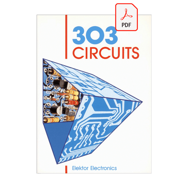
Elektor Digital 303 Circuits (E-book)
Like its predecessors in the 300 series of electronics projects books, 303 Circuits is aimed at the active electronics enthusiast, professional or amateur. Since the series was started in the early 1980s, many thousands of readers have found in these books that new approach, new concept, or new circuit they were looking for. In 303 Circuits you will find new ideas, new concepts and new circuits covering the gamut of electronics. The book is arranged in subject sections to make it easier for you to find the circuit or idea you are looking for.
€ 29,95
Members: € 26,96
-

JOY-iT JOY-iT PS1440-C-Pro Programmable Laboratory Power Supply with RS485 (1440 W)
With the JOY-iT PS1440-C-Pro, you get a programmable laboratory power supply that delivers DC voltages ranging from 0.01 to 60 V and DC currents from 0.01 to 24 A at the voltage output. The intuitive control panel allows you to program, store, and recall up to 9 different DC voltage settings. You can also configure individual protection and limiting functions—such as overvoltage protection. All settings are easily adjusted via the keypad and/or rotary control and are clearly shown on the high-resolution 2.4" color display. For enhanced connectivity, the PS1440-C-Pro includes an RS485 interface for robust, long-distance communication. This makes it ideal for complex setups where signal stability, noise immunity, and reliable data transfer are critical. The included connector ensures a secure connection, improving the overall reliability and performance of your laboratory equipment setup. Features Complete device ready for immediate use RS485 interface Battery charging function Values can be entered conveniently via keypad Over current & over voltage protection adjustable Integrated RTC, NTC temperature sensor Included detailed documentation in English, German & French Specifications Input voltage 230 V Output voltage 060 V Output current 0-24 A Output power 0-1440 W Input voltage accuracy ±1% +5 digits Output voltage accuracy ±0.3% +3 digits Output current accuracy ±0.5% +5 digits Battery voltage ±0.5% +3 digits Input voltage measurement resolution 0.01 V Output voltage measurement resolution 0.01 V Current measurement resolution 0.01 V Battery voltage measurement resolution 0.01 V Response time in constant voltage mode 2 ms @ 0.1-5 A Load regulation in constant voltage mode ±0.1% +2 digits Load regulation in constant current mode ±0.1% +3 digits Measuring range electric charge 0-9999.99 Ah Measuring range energy 0-9999.99 Wh Statistical errors in electric charge & energy ±2% Output ripple 100 mV VPP @ 12 V150 mV VPP @ 24 V Sensor temperature detection range −10~100°C (0-200°F) Sensor temperature detection accuracy ±3°C (±6°F) Working mode Step-down operation Screen brightness setting Level 0-5, 6 levels in total Permissible working temperature −10~40°C (0-104°F) Dimensions 170 x 93 x 340 mm Included JOY-iT PS1440-C Power Supply 2-pin connector for RS485 interface Power cord Manual Downloads Datasheet MODBUS Protocol PC Software Driver for Windows
€ 499,00
Members: € 449,10
-

Weller Weller WE1010 Digital Soldering Station (70 W)
High-quality soldering station with the most important tools and consumables, ideal for universal soldering applications. Features 1-Channel Power Unit, digital, 70 W Power unit, 1 channel with soldering iron WEP 70 and safety rest PH 70 70W solder iron with ergonomic handle and providing toolless tip change ESD safe station, iron and heat-resistant silicon cable for safe handling Using ET soldering tips Standby mode and auto setback conserves energy, protects equipment Password-protected to preserve settings Specifications Dimensions: 150 x 120 x 98 mm Weight: 1.4 kg Display: Digital LC Display Temperature range: Adjustable from 100°C - 450°C (200°F - 850°F) Voltage: 230 V Channels: 1 Temperature range (depends on tool) °C: 100-450 Temperature range (depends on tool) °F: 200-850 Temperature accuracy °C: Average tip temperature can be „offset“ to +/- 5°C at idle with no load Temperature accuracy °F: Average tip temperature can be „offset“ to +/- 9°F at idle with no load Temperature stability °C: ±6 Temperature stability °F: ±10 Heat-up time (ca) in seconds (50-350°C / 120-660°F): 28 sec. Heating output: 85 W
€ 157,60
-

OWON OWON SDS1104 4-ch Oscilloscope (100 MHz)
The OWON SDS1104 oscilloscope is a practical choice for engineers, technicians, students, and hobbyists who need accurate signal analysis without the cost of high-end instruments. With its 100 MHz bandwidth and 1 GSa/s sampling rate, it reliably captures low- to mid-frequency signals, making it well suited for electronics development, troubleshooting, and educational use. Equipped with a 7-inch color TFT display, the SDS1104 provides clear waveform visualization, while automatic measurement functions and FFT analysis help users quickly evaluate frequency, voltage, and timing parameters. Advanced math operations, cursor measurements, and multiple trigger modes add further flexibility, making the oscilloscope a versatile tool for a wide range of testing scenarios. Specifications Bandwidth 100 MHz Sample Rate 1 GS/s Horizontal Scale (s/div) 5ns/div - 1000s/div, step by 1 - 2 - 5 Channel 4 Display 7" color LCD, 800 x 480 pixels Input Coupling DC, AC and GND Vertical Resolution (A/D) Vertical Resolution (A/D) Vertical Sensitivity 5mV/div - 5V/div (at input) Trigger Type Edge, Video Trigger Mode Auto, Normal and Single Waveform Math +, -, x, ÷, invert, FFT Fuse 2A, T class, 250 V Dimension (W x H x D) 301 x 152 x 70 mm Weight 1.1 kg Included 1x OWON SDS1104 Oscilloscope 1x Mains power cord 1x CD Rom 1x Quickstart Guide 1x USB Cable 4x Oscilloscope probe 1x Probe Adjust Downloads Datasheet Manual
€ 249,00
-

OWON OWON P4603 DC Power Supply (180 W)
This OWON DC Power Supply has a small body and is easy to carry due to its light weight. Featuring a 3.7" TFT LCD display, it has a maximum output power of 180 W and a resolution of 1 mV/1 mA. Features Channel Single Channel Output Total Output Power 180 W Channel Output 0 - 60 V / 0 - 3 A × 1-CH Display 3.7' color LCD display Dimension 117 mm(L) × 194 mm(H) × 295 mm(D) Weight Approx. 5.8 kg Interface RS232 Specifications Rated Output (0 ℃ - 40 ℃) Voltage 0 - 60 V Current 3 A Load Regulation Voltage ≤ 0.01% + 3 mV Current ≤ 0.01% + 3 mA Power Regulation Voltage ≤ 0.01% + 3 mV Current ≤ 0.01% + 3 mA Setting Resolution Voltage 1 mV Current 1 mA Readback Resolution Voltage 1 mV Current 1 mA Setpoint accuracy (within 12 months) (25 ℃ ± 5 ℃) Voltage ≤ 0.03% + 10 mV Current ≤ 0.1% + 5 mA Readback Resolution (25 ℃ ± 5 ℃) Voltage ≤ 0.03% + 10 mV Current ≤ 0.1% + 5 mA Ripple/Noise (20 Hz - 20 MHz) Voltage (Vp-p) ≤ 4 mVp-p Voltage (Vrms) ≤ 1 mVrms Current (rms) ≤ 4 mArms Output temperature coefficient(0 ℃ - 40 ℃) Voltage ≤ 0.03% + 10 mV Current ≤ 0.1% + 5 mA Readback temperature coefficient Voltage ≤ 0.03% + 10 mV Current ≤ 0.1% + 5 mA Response Time 100 μs Storage 5 groups of data Working Temperature 0 - 40 ℃
€ 164,57
-

OWON OWON DGE3062 2-ch Arbitrary Waveform Generator (60 MHz)
The OWON DGE3062 is a 14-bit function generator with a bandwidth of 60 MHz. It has 5 basic waveforms, 160 built-in arbitrary waveforms and the following comprehensive modulation functions: AM, FM, PM, PWM, FSK, 3FSK, 4FSK, PSK, ASK, BPSK, OSK, DSBAM, QPSK, SUM, sweep, Burst. Features Max. 60 MHz frequency output, 300 MSa/s Sample rate 14 bits Vertical Resolution, 100K Arb waveform length Comprehensive waveform output: 5 basic waveforms, and 160 built-in arbitrary waveforms Comprehensive modulation functions: AM, FM, PM, PWM, FSK, 3FSK, 4FSK, PSK, ASK, BPSK, OSK, DSBAM, QPSK, SUM, sweep, Burst SCPI and LabVIEW supported 3.6 inch LCD (480 x 272 pixels) Specifications Channel 2 Frequency Output 60 MHz Sample Rate 300 MSa/s Vertical Resolution 14 bits Waveform Standard Waveform Sine, square, pulse, ramp, noise Arbitrary Waveform Exponential rise, exponential fall, sin(x)/x, step wave, and others, total 160 built-in waveforms Frequency (resolution 1 μHz) Sine 1 μHz-60 MHz Square 1 μHz ~ 20 MHz Pulse 1 μHz ~ 20 MHz Ramp 1 μHz ~ 2 MHz Noise 20 MHz (-3 dB, typical) Arbitrary Waveform 1 μHz ~10 MHz Arbitrary Waveform Length 2 points – 100K points Sample Rate 300 MSa/s Amplitude Into 50Ω load 1mVpp ~ 10Vpp (≤10Hz), 1mVpp ~ 5Vpp (≤60 MHz) DC Offset Range (AD+DC ±(10 Vpk – Amplitude Vpp/2) high resistance±(5 Vpk – Amplitude Vpp/2) 50 Ω DC offset resolution 1 mV or 4 digits Load Impedance 50 Ω (typical) DC offset Accuracy ±(1% of |setting| + 1 mV + amplitude Vpp * 0.5%) Modulation Type AM,FM, PM, PWM, FSK, 3FSK, 4FSK, PSK, ASK, BPSK, OSK, DSB-AM, QPSK, SUM, Sweep, Burst Frequency Counter Function Frequency, period Frequency Range 100 MHz ~ 100 MHz Frequency Resolution 6 digits Input/Output Display 3.6” LCD Input mode External modulation input, external trigger input, external reference clock input/output Communication Interface USB Host, USB Device Mechanical specifications Dimensions (W x H x D) 200 x 92 x 157 mm Weight 0.8 kg Included 1x OWÒN DGE3062 Arbitrary Waveform Generator 1x Power Cord 1x Quick Guide 1x USB Cable 1x Q9 Cable 1x BNC to Alligator Clip Downloads Quick Guide Manual Software
€ 212,50
-

OWON OWON SPS6051 Fanless DC Power Supply (150 W)
The OWON SPS6051 Fanless Programmable DC Power Supply (150 W) delivers ultra-quiet, high-precision performance with 10 mV/1 mA accuracy and advanced heat dissipation for long-term reliability. Featuring comprehensive protection, a USB interface with SCPI support for remote control, and a 2.8-inch TFT LCD screen, it is the perfect choice for laboratories, electronics testing, and research. Features Fanless design: Ultra-quiet operation, reducing vibration noise and minimizing the potential failure risks associated with traditional cooling fans. Excellent heat dissipation design: Ensures a controlled temperature rise, allowing long-term operation under full load conditions and extending internal component longevity. Lightweight and ultra-thin design. Output accuracy up to 10 mV/1 mA. Supports List waveform editing and output, with four memory shortcut parameters for quick and convenient access. Integrated protection features include overvoltage, overcurrent, overtemperature, and input undervoltage protection for enhanced safety. Built-in discharge circuit prevents residual high voltage risks when the power is turned off. USB communication interface with SCPI protocol support, enabling PC programming and remote control for simplified user management. 2.8-inch TFT LCD screen Specifications Model SPS6051 SPS3081 Rated Output (0°C-40°C) Voltage 0-61 V 0-31 V Current 0-5.1 A 0-8.1 A Power 150 W 120 W Load Regulation Voltage ≤30 mV Current ≤20 mA Power Regulation Voltage ≤30 mV Current ≤20 mA Setting Resolution Voltage 10 mV Current 1 mA Readback Resolution Voltage 10 mV Current 1 mA Seting Accuracy (25°C ±5°C) Voltage ≤0.05% ±20 mV ≤0.1% ±20 mV Current ≤0.05% ±20 mA ≤0.2% ±20 mA Readback Accuracy (25°C ±5°C) Current ≤0.05% ±20 mV ≤0.1% ±20 mV Voltage ≤0.05% ±20 mV ≤0.2% ±20 mA Ripple/Noise Voltage ≤30 mVp-p ≤30 mVp-p Voltage ≤4 mVrms ≤5 mVrms Current ≤10 mAp-p ≤30 mAp-p Output temperature coefficient (0°C-40°C) Voltage 100 ppm/°C Current 200 ppm/°C Readback temperature coefficient Voltage 100 ppm/°C Current 200 ppm/°C Response Time (50-100% rated load) ≤1.0 ms Storage 4 groups of data Working Temperature 0-40°C Display 2.8-inch color LCD display Interface USB Dimensions (W x H x D) 82 x 142 x 226 mm Weight 1.8 kg Included 1x OWON SPS6051 Power Supply 2x Test leads 1x Power cord 1x Manual Downloads Datasheet User Manual Programming Manual PC Software
€ 134,31
-
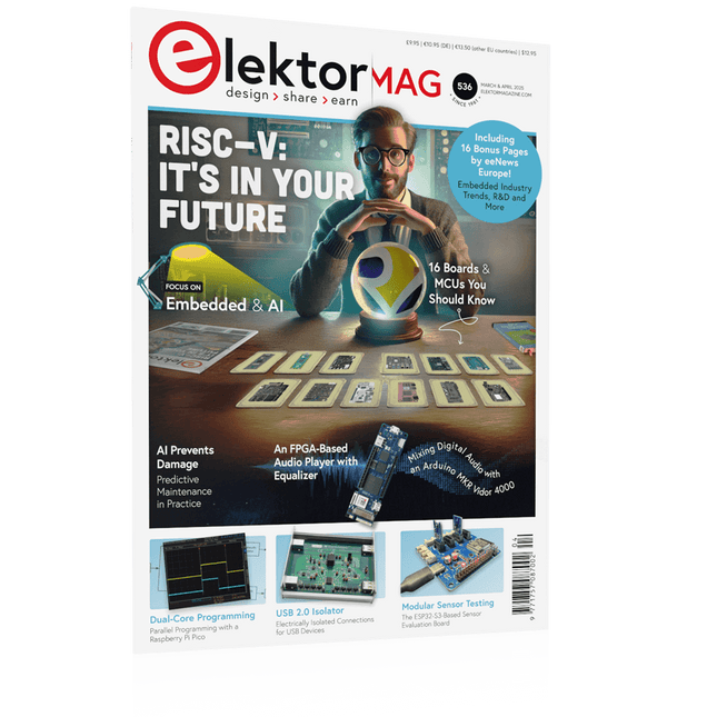
Elektor March/April 2025 (EN)
Elektor GREEN and GOLD members can download their digital edition here. Not a member yet? Click here. The RISC-V Open-Source Processor Architecture16 Boards and MCUs You Should Know An FPGA-Based Audio Player with Equalizer (1)Mixing Digital Audio with an Arduino MKR Vidor 4000 Laser Head for Pico-Based Sand ClockDrawing with Light Enter the STM32 Edge AI Contest A Multi-Sensor Environmental Monitoring System for PlantsWireless Measurement of Water Supply and Light Conditions Maixduino AI-Powered Automatic DoormanFace Detection with a Camera Embedded Electronics 2024AI Is Set to Redefine the Industry Charge-Based In-Memory Compute at EnCharge AI AI Inferencing at 10 Times Lower Power and 20 Fold Lower Cost Click Board Helps Develop and Train ML Models for Vibration Analysis The Elektor Mini-WheelieA Self-Balancing Robot Kit MCU, I See YouMCUViewer Open-Source Multiplatform Debugging Tool USB 2.0 IsolatorElectrically Isolated Connections for USB Devices Intervention Before DamagePredictive Maintenance in Practice SPoE – Electromagnetic CompatibilitySingle-Pair with Power-Over-Ethernet Through the Eyes of EMC Color TV: A Wonder of Its TimeCreating a New World ECG Graph MonitoringAn Implementation with Hexabitz Modules and an STM32CubeMonitor The Battle for AI at the Edge HaLow Hits Record 16-km Wi-Fi Distance at 900 MHz First CHERI RISC-V Embedded Chip and Early Access Programme Third-Generation Wildfire Detection Uses Satellite Links From Life’s ExperienceChoice Overload Starting Out in Electronics……Continues Filtering and Controls Tone Quasi-Analog ClockworkA Remake of an Elektor Classic A Modular Approach to Sensor TestingThe ESP32-S3-Based Sensor Evaluation Board 2025: An AI OdysseyThe Rise of Foundation Models and Their Role in Democratizing AI Raspberry Pi Standalone MIDI Synthesizer (1)Preparing a Platform for Some Edge AI Experiments Err-lectronicsCorrections, Updates, and Readers’ Letters Universal AI RISC-V Processor Does It All — CPU, GPU, DSP, FPGA CEO Interview: Ventiva’s Thin and Cool Tech Dual-Core Programming with a Raspberry Pi PicoVenture Into the World of Parallel Programming
€ 10,95
-

Elektor Academy Pro MicroPython for STM32 (Programming Course)
This complete STM32 microcontroller programming course features a textbook, a component kit, hands-on projects, and a comprehensive online course. It is ideal for step-by-step learning of embedded systems programming in MicroPython using a practical, hands-on approach. A Practical Introduction to Embedded Systems with the STM32 This course is designed for people who are new to embedded systems and looking for a structured, example-driven way to get started. A kit of parts comprising LEDs and resistors, switches, sensors and actuators, displays, a breadboard and wires, and more is included. These are used in the course to illustrate example applications. No prior experience with MicroPython or embedded development is required. Each section features hands-on examples and mini projects designed to reinforce key concepts and inspire deeper exploration. By the end of the course, you’ll be able not only to reproduce the examples but also to build on them with your own ideas and applications. What Will You Learn? Microcontroller programming in MicroPython on the STM32 using the Thonny IDE Working with Digital I/O, read buttons and encoders, control LEDs and relays Read analog inputs, voltages, and analog sensors Generating analog output signals and PWM Use serial communication like UART, I²C and SPI to control displays and read digital sensors and SD cards Managing time Working with interrupts Real-time sensor input and control via buttons, LEDs, and displays Control actuators like relays and servo motors Who Is It For? Students and self-learners exploring embedded systems Makers and IoT enthusiasts looking to improve their hardware skills Educators and trainers seeking ready-to-teach material What's Inside the Box? Access to the full course on the Elektor Academy Pro Learning Platform STM32 NUCLEO-F411RE microcontroller board + USB cable Book: MicroPython for STM32 Downloadable project files for every module Component Box: 2× LED, red, 5 mm LED, green, 5 mm 3× Resistor, 470 Ω, 0.25 W LDR Potentiometer, 10 kΩ, linear Pushbutton Rotary encoder module Relay module DHT22 Humidity & Temperature Sensor TM1637-compatible 4-digit 7-segment display MPU-6050 IMU with headers SSD1306-compatible I²C OLED display Micro SD card adapter with header Buzzer SG90 Micro Servo ILI9341-compatible SPI 240×320 TFT display 20× Jumper wires Breadboard
€ 99,95€ 84,95Best Price
-

Elektor Digital Elektor July/August 2026 (PDF) EN
Elektor GREEN and GOLD members can download their digital edition here. Not a member yet? Click here. MultiRF Dev BoardA Platform for Evaluating Short- and Long-Range Wireless Protocols Elektor at 65Disrupting Electronics Since 1961 Wi-Fi-Based Person Detection on an ESP32When Your Router Becomes a Motion Sensor Wireless ScalesFour Small Scales = One Big Scale Walter, the Compact IoT ModuleESP32-S3 SoC, LTE-M/NB-IoT 5G Modem, and GNSS Receiver 3- and 4-Wire RTD Sensors ConditioningWith Full-Scale Adjustment and Cable Compensation 3-in-1 2-Channel Oscilloscope/Generator/MultimeterA Review of The Fnirsi 2D15P electronica Fast Forward 2026 Invites Startups and Industry Partners EcologgingA Modular Environmental IoT Station for Field Research Wireless Connectivity in Medical ApplicationsAlways on the Pulse with Bluetooth LE AudiotronicsHum Reduction Increasing Agricultural Efficiency with AI Modeling and SensorsBoosting Agricultural Productivity OPC UA — An OverviewPlatform-Independent Data Exchange Redox Meter Instrumentation Amplifier for Physics and Engineering Experiments Active Differential Audio FiltersFor Professional Crossovers and More Elektor Community Perspectives on IoT & Sensors Telegram-Controlled Water Heater Interface ModuleA Solution Based on an ESP32 and Arduino Software 2026: An AI OdysseyWhatever Happened to Fuzzy Logic? Err-lectronics Alarm Signal Injector Plus PowerTools for Finding Broken Wires
€ 9,50
-

Elektor Digital PIC Cookbook for Virtual Instrumentation (E-book)
The software simulation of gauges, control-knobs, meters and indicators which behave just like real hardware components on a PC’s screen is known as virtual instrumentation. In this book, the Delphi program is used to create these mimics and PIC based external sensors are connected via a USB/RS232 converter communication link to a PC. Detailed case studies in this Book include a virtual compass displayed on the PC’s screen, a virtual digital storage oscilloscope, virtual -50 to +125 degree C thermometer, and FFT sound analyser, a joystick mouse and many examples detailing virtual instrumentation Delphi components. Arizona’s embedded microcontrollers – the PIC's are used in the projects and include PIC16F84A, PIC16C71, DSPIC30F6012A, PIC16F877, PIC12F629 and the PIC16F887. Much use is made of Microchip’s 44 pin development board (a virtual instrument ‘engine)’, equipped with a PIC16F887 with an onboard potentiometer in conjunction with the PIC’s ADC to simulate the generation of a variable voltage from a sensor/transducer, a UART to enable PC RS232 communications and a bank of 8 LED's to monitor received data is also equipped with an ISP connector to which the ‘PICKIT 2’ programmer may easily be connected. Full source code examples are provided both for several different PIC’s, both in assembler and C, together with the Pascal code for the Delphi programs which use different 3rd party Delphi virtual components.
€ 19,95
Members: € 17,96
-
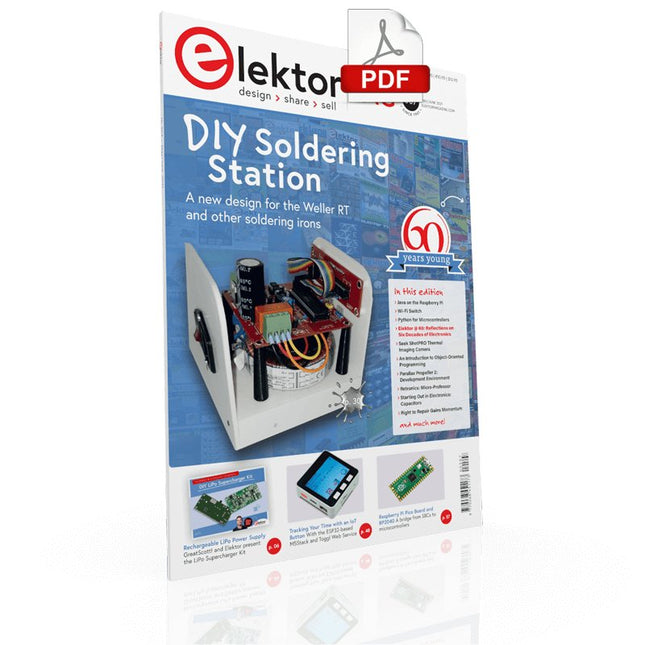
Elektor Digital Elektor May/June 2021 (PDF)
Elektor Magazine EN May/June 2021 (PDF)
€ 7,50
-

iFixit iFixit Magnetic Project Mat
The 8x10" iFixit Magnetic Project Mat catches and securely holds screws as you pull them out of a device. Now you can stop worrying about keeping track of all the loose screws and focus on your repair. Screws and small parts will remain right where you left them. For laptops with hundreds of screws, use the whole mat as a screw guide and keep careful location notes. Included is a pen – made by Staedtler, producer of top-of-the-line pens and pencils for artists and architects – that was specially designed for the Project Mat. The Lumocolor Correctable pen resists smears and won't wipe away with a casual brush of your hand. When your repair is complete, use the eraser tip or a dry cloth to wipe the ink away clean. Features Organize all your small parts while you work on a device. The dry-erase surface lets you keep notes and location sketches. Reduces reassembly time by up to 40% while preventing errors.
€ 19,95
-

Elektor Edge Impulse Guest Edition 2025 (EN)
Elektor GREEN and GOLD members can download their digital edition here. Not a member yet? Click here. What to expect This Elektor edition guest-edited by Edge Impulse explores the edge AI workflow, from data collection and model training to deployment and optimization: End-to-End Edge AIA hands-on object detection series that walks through the complete machine learning pipeline on embedded hardware. High-Resolution, High-Speed Object Counting (Nvidia Jetson Nano, TensorRT)Pushing inference speed and precision for visual counting applications. PCB Defect Detection with Computer Vision (Raspberry Pi)Smarter manufacturing through embedded vision. Smart Building Ventilation with Sensor FusionAI-powered environmental optimization for energy efficiency. Analog Meter Reading (Arduino Nicla Vision)A TinyML approach to automating analog infrastructure. Smart Appliance Control Using Voice Commands (Nordic Thingy:53)Speech recognition at the edge. Liquid Classification with TinyML (Seeed Wio Terminal + TDS Sensor)Combining IoT sensing and embedded ML for fluid analysis. Surgery Inventory Object DetectionApplying real-time vision to healthcare logistics. Plus, the magazine includes exclusive interviews with: Edge Impulse co-founders Zach Shelby and Jan Jongboom; Qualcomm Technologies VP of product management Manny Singh; and EDGE AI FOUNDATION CEO Pete Bernard. Also included are a Tech the Future essay titled "AI at the Edge: Powering the Next Generation of Devices," an Industry Case Study on GlobalSense, and more. Contents What the Heck Is Edge AI Anyway?Bringing Intelligence to the Device Meet Edge Impulse StudioEasily Build and Deploy Edge AI Models Keyword Spotting with Edge ImpulseCollect, Train, and Deploy Smart Appliance Control Using Voice Commands with the Nordic Thingy:53 Key Terms for Understanding Edge AI and Machine Learning Crash Course: Getting Started with Edge ImpulseLearn to Collect, Train, and Deploy an ML Model with the Arduino Nano 33 BLE Sense A New Chapter for ArduinoFrom Hobby Board to Edge Computing Powerhouse Getting Started with Object Detection on Edge Devices PCB Defect DetectionComputer Vision with Raspberry Pi Scaling AI to the Smallest Devices Optimizing Power Efficiency in Battery-Driven Edge AI Devices AI ToasterWhen Edge AI Meets Breakfast Thundercomm Rubik Pi 3Raspberry Pi Familiarity Meets Edge AI Leadership, Embedded ML, and the Edge Revolution Vision Language Models for the EdgeCascading Models for Better Reliability Get to Know Edge ImpulseQuestions from the Elektor Community Project Update #5: ESP32-Based Energy MeterUsing Edge AI to Recognize Household Loads Motion Recognition with Anomaly DetectionAn End-to-End Tutorial Smart Ventilation System: Fusing Sound and Environmental DataA Dual-MCU Machine Learning Approach for Automated Window and Louver Control Bringing Voice Control to Earbuds and Headsets AI at the Edge: Powering the Next Generation of Devices
€ 14,90
-
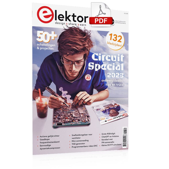
Elektor Digital Elektor Circuit Special 2023 PDF (NL)
Elektor GREEN en GOLD leden kunnen deze uitgave hier downloaden.Nog geen lid? Klik hier om een lidmaatschap af te sluiten. Mini-zonnevoedingzon in, 3,3 V uit Solid-state stereo-audioschakelaarklikvrij en zonder bewegende onderdelen Grote RGB-digitmet through-hole WS2812 LED’s Microfoon-voorversterker met 48V-fantoomvoedingvoor podcasting en pro-audio Blokgolfgeneratoren met regelbare duty cycle en frequentiesimpele schakelingen met CMOS- en TTL-IC’s Eenvoudige dynamiekcompressorsofte aansturing, warm geluid Simpel elektronisch slot Actieve gelijkrichtervoor 2...40 V bij maximaal 3 A met tegenstroomonderdrukking Actieve boxen in- en uitschakelen Ongebalanceerd/gebalanceerd-convertermet RF-filter en DC-bescherming 2023: een AI-odysseewaar komt het vandaan en waar gaat het naar toe? Snelheidsregelaar voor ventilatormet handmatige en thermostaatmodus Laatste nieuwtjes van Arduino Project Hubnieuwe projecten uit de community Overbelastingsmonitorbewaakt netsnoeren Transistorloos knipperlicht in het donkeroscillator met alleen tweedraads onderdelen Morsecode-generatorvoor gebruik als baken of leermiddel! Programmeerbare video-DACvoor elk formaat tot RGB888 Kleintje klavierzonder bewegende onderdelen Dubbel-dobbel zonder microprocessordubbele dobbelsteen op een enkele print – plus enkele ontwerptrucs Elektronische vogelverschrikker Amusante, inspirerende en verbazingwekkende schakelingen LC/LP/HA-thermometernauwkeurige metingen en een binair display THD-generatorvervorming, maar dan opzettelijk Overtemperatuur-indicator met thyristorelektronische onderdelen ongebruikelijk gebruikt Een PTC-flipflop Sociale vogeleen tsjilpende Elektor Klassieker Neonlamp plus microcontroller Temperatuurgestabiliseerde IC-stroombronneutraliseer de temperatuurdrift van deze driebeners Regelbare tweede-orde hogetonen-boostergehoorsteuntje voor ouderen Edwin komt naar huisherinneringen na 53 jaar Eénarmige bandieteen eenvoudige, leuke, nostalgische en leerzame Elektor-klassieker! Eenvoudige digitaal gestuurde variabele weerstand Lekdetectorbeveiligt en alarmeert bij lekkages Eco-timer met automatische uitschakelingverbruikt niets in uitgeschakelde toestand! ChatGPT en Arduino Zenermetermeet de Z-spanning van Z-diodes ≤ 100 V Servotester ESP32 Windows-controller met gratis software Analoge en mixed-signal IC’s van Microchipzuinige signaalverwerking Interfacenormenfilter en overspanningsbeveiliging voor de I²C-bus Li-Ion accumonitorrestlading-indicator geeft visuele feedback PS/2-muis als draai-encoder (en meer...) Simpele schemerschakelaarvoor bestaande lampen of installaties Controller voor waterpompbereid je voor op hoogwater Kerstbal met FM-zonneradiomeer heb je voor de kerst niet nodig Trillingssensor met relaistik of schud om in te schakelen Doorgangstestergevoelig en niet storend In- en uitschakelen met een drukknop Regeling voor mini-boor (2023)een ontwerp uit 1980 herzien Digitale trillingssensorzet trillingen om in nauwkeurig getimede pulsen Ompoolbeveiliging met kleine spanningsval Goedkope frequentiestandaard Kleine DCF77-simulatornauwkeurige fake-tijdstandaard De Lilygo T-PicoC3combineert RP2040 en ESP32-C3 met een full-color TFT-display Hexadoku
€ 9,95
-
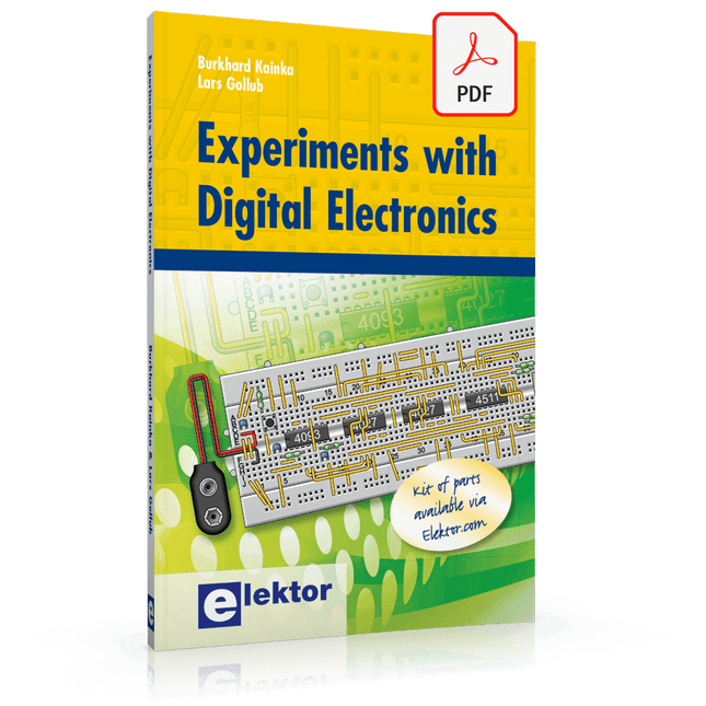
Elektor Digital Experiments with Digital Electronics (E-book)
The field of digital electronics is central to modern technology. This e-book presents fundamental circuits using gates, flip-flops and counters from the CMOS 4000 Series. Each of the 50 experiments has a circuit diagram as well as a detailed illustration of the circuit’s construction on solderless breadboard. Learning these fundamentals is best done using practical experiments. Building these digital circuits will improve your knowledge and will be fun to boot. Many of the circuits presented here have practical real-life applications. With a good overview of the field, you’ll be well equipped to find simple and cost-effective solutions for any application. The e-book is targeted essentially at students, trainees and anyone with an interest in and requiring an introduction to digital control electronics. Moreover, the knowledge gleaned here is the foundation for further projects in the field of microcontrollers and programming.
€ 24,95
Members: € 22,46


