Bestsellers
-

Elektor Digital RFID (E-book)
RFID technology has conquered many areas in which barcodes, magnetic strips and contact smartcards were used previously. Everyday applications, such as electronic ticketing, access cards, debit cards and electronic identity documents would not be possible without this technology. MIFARE is the most widely used RFID technology, and this book provides a practical and comprehensive introduction to it. Among other things, the initial chapters cover physical fundamentals, relevant standards, RFID antenna design, security considerations and cryptography. The complete design of a reader’s hardware and software is described in detail. The reader’s firmware and the associated PC software support programming using any .NET language. The specially developed PC program, “Smart Card Magic.NET”, is a simple development environment that supports sending commands to a card at the click of a mouse, as well as the ability to create C# scripts. Alternatively, one may follow all of the examples using Visual Studio 2010 Express Edition. Finally, the major smart card reader API standards are introduced. The focus is on programming contactless smartcards using standard PC/SC readers using C/C++, Java and C#.
€ 34,95
Members: € 31,46
-
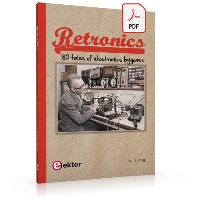
Elektor Digital Retronics (E-book)
Quite unintentionally a one-page story on an old Heathkit tube tester in the December 2004 edition of Elektor magazine spawned dozens of ‘Retronics’ tales appearing with a monthly cadence, and attracting a steady flow of reader feedback and contributions to the series. Since launching his Retronics columns, Elektor Editor Jan Buiting has never been short of copy to print, or vintage equipment to marvel at. This book is a compilation of about 80 Retronics installments published between 2004 and 2012. The stories cover vintage test equipment, prehistoric computers, long forgotten components, and Elektor blockbuster projects, all aiming to make engineers smile, sit up, object, drool, or experience a whiff of nostalgia. To reflect that our memories are constantly playing tricks on us, and honoring that “one man’s rubbish is another man’s gem”, the tales in the book purposely have no chronological order, and no bias in favor of transistor or tube, microprocessor or discrete part, audio or RF, DIY or professional, dry or narrative style. Although vastly diff erent in subject matter, all tales in the book are told with personal gusto because Retronics is about sentiment in electronics engineering, construction and repair, be it to reminisce about a 1960s Tektronix scope with a cleaning lady as a feature, or a 1928 PanSanitor box for dubious medical use. Owners of this book are advised to not exceed one Retronics tale per working day, preferably consumed in the evening hours under lamp light, in a comfortable chair, with a piece of vintage electronic equipment close and powered up.
€ 24,95
Members: € 22,46
-
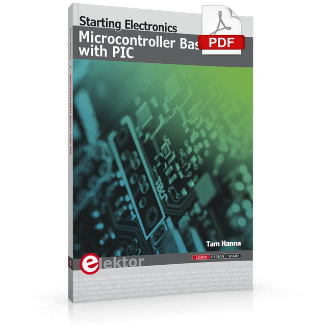
Elektor Digital Microcontroller Basics with PIC (E-book)
In this book the author presents all essential aspects of microcontroller programming, without overloading the reader with unnecessary or quasi-relevant bits of information. Having read the book, you should be able to understand as well as program, 8-bit microcontrollers. The introduction to microcontroller programming is worked out using microcontrollers from the PIC series. Not exactly state-of-the-art with just 8 bits, the PIC micro has the advantage of being easy to comprehend. It is offered in a DIP enclosure, widely available and not overly complex. The entire datasheet of the PIC micro is shorter by decades than the description of the architecture outlining the processor section of an advanced microcontroller. Simplicity has its advantages here. Having mastered the fundamental operation of a microcontroller, you can easily enter into the realms of advanced softcores later. Having placed assembly code as the executive programming language in the foreground in the first part of the book, the author reaches a deeper level with ‘C’ in the second part. Cheerfully alongside the official subject matter, the book presents tips & tricks, interesting measurement technology, practical aspects of microcontroller programming, as well as hands-on options for easier working, debugging and faultfinding.
€ 32,95
Members: € 29,66
-
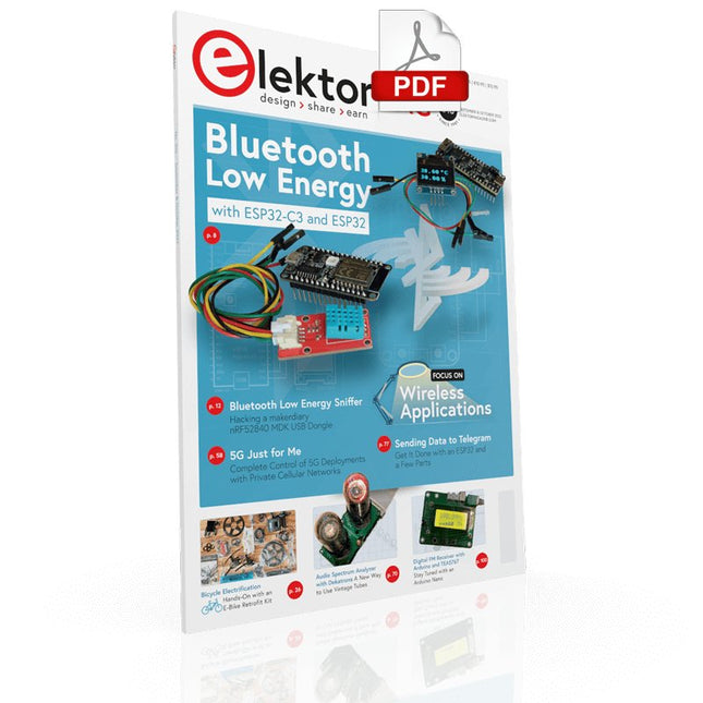
Elektor Digital Elektor September/October 2022 (PDF)
Elektor GREEN and GOLD members can download their digital edition here. Not a member yet? Click here. electronica fast forward 2022 Start- & Scale-Up AwardsPreparations Speeding Up! Bluetooth Low Energy with ESP32-C3 and ESP32You Don’t Always Need to Choose Wi-Fi! Bluetooth Low Energy SnifferHacking a makerdiary nRF52840 MDK USB Dongle Magic RGB LED CubeHardware Design Around an RP2040 Auto On/Off for Solder Paste Compressor Elektor Video ContentLivestreams, Webinars, and Courses for Engineers and Pro Makers Bicycle ElectrificationHands-On with an E-Bike Retrofit Kit Starting Out in ElectronicsMultiplying Voltages From Life’s ExperienceSidelines Teensy 4.0Why Is This Board So Fast? Audio Power Amplifier Simulation with TINAThe Try-Before-You-Build Approach Develop and Operate Your LoRaWAN IoT NodesSample Chapter: Dragino LHT65, LDS01, and LDS02 LoRaWAN Modules Err-lectronicsCorrections, Updates and Readers’ Letters 5G Just for MeGaining Complete Control of 5G Deployments with Private Cellular Networks Infographics 7-8/2022 How Does My Device Learn to Transmit?Applications with Wi-Fi Interfaces Smartphones are the Heart of the IoT Audio Spectrum Analyzer with DekatronsA New Way to Use Vintage Tubes Sending Data to TelegramGet It Done with an ESP32 and a Few Parts A Fliege Notch Filter for Audio MeasurementsMake Better Measurements with a Notch Filter CO2 Meter TeardownIs It Hackable for Your Projects? PUT-ting It All TogetherThe Programmable Unijunction Transistor Explained Round Touchscreen for Raspberry PiHyperPixel 2.1 Round from Pimoroni Remote Sensing with Connection Loss DetectionUsing nRF24L01+ Modules Digital FM Receiver with Arduino and TEA5767Stayed Tuned with an Arduino Nano Changing an OLED Interface from SPI to I²C HomeLab ToursA Hobby Does Not Retire A Decade of Ethics in ElectronicsTessel Renzenbrink Reflects on the Digital Society and More HexadokuThe Original Elektorized Sudoku
€ 7,50
-
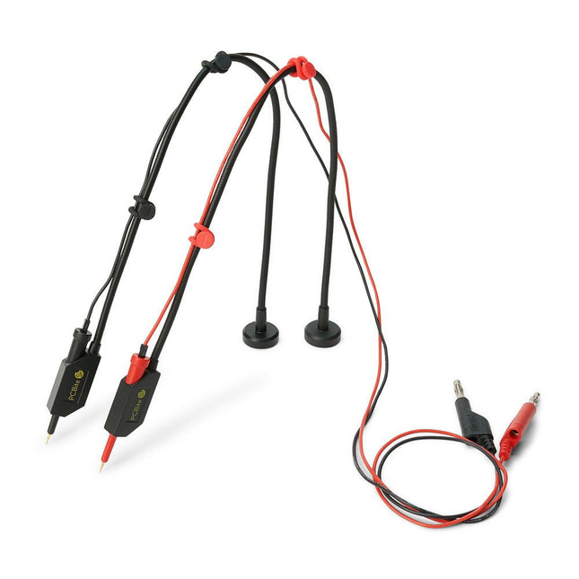
Sensepeek Sensepeek 6011 2x SQ10 Probe for DMM (red/black)
The SQ series of handsfree PCBite probes from Sensepeek are insulated, come with included color-coded cable holders and have a lower point of gravity making them even more stable compared with the original SP series of probes. All the loved features of handsfree measurement, exchangeable fine pitch spring tipped test needle and the minimalistic design is maintained to make traditional sized and handheld probes obsolete. Features All handsfree probes from Sensepeek makes instant measurements or long triggering sessions a breeze. No more soldering wires to connect your probe or complicated tools to setup, just positioning the probe needle on any test point or component in the signal path and release. Saves time and frustration during development, verification and repairs. The minimalist design and the spring-loaded test needle makes it possible to simultaneously measure on fine pitch components and nearby signals. Both length and weight of the SQ probes are perfectly balanced to be used with PCBite PCB holders and base plate which is a must for handsfree function. The probe holder comes with a powerful magnet in the base, as for all PCBite probes and holders which makes the probe easy to place and reposition. The SQ series of probes can be used handheld without the probe holder as they have an insulated grip but their full potential is used when measuring handsfree. Included 2x SQ10 probes and pin tipped test needles (red/black) 2x Banana to dupont test wires (red/black) 1x Set of cable holders (red/black) 2x Extra test needles Downloads User guide
€ 54,45
-
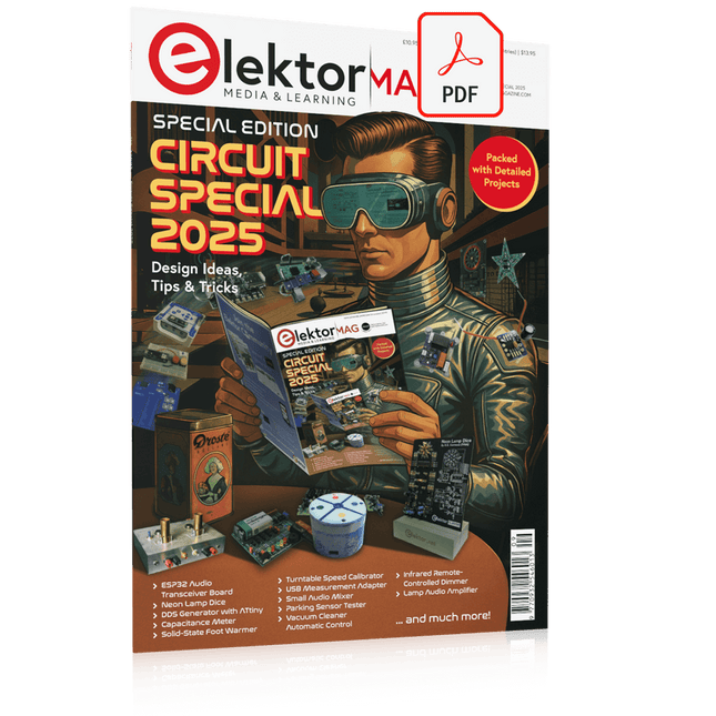
Elektor Digital Elektor Circuit Special 2025 (PDF) EN
Elektor GREEN and GOLD members can download their digital edition here. Not a member yet? Click here. USB Measurement AdapterTesting Current and Signal Quality of USB Ports 4...20 mA Current Output for Arduino UnoA Reliable, EMI-Insensitive Current Loop Interface Vacuum Cleaner Automatic ControlKeep Your Tools’ Work Area Clean DDS Generator with ATtiny Opamp-Tester V2New PCB – Now Also Suitable for SMDs 550-mW “Lamp” Audio AmplifierGet the Warm Sound of Vacuum Tubes With Ease Fuse GuardMonitoring a Fuse with a Flashing LED HQ RIAA PreamplifierGet the Most Out of Your Vinyl Records! Turntable Speed CalibratorAn Arduino-Based 100–120 Hz Strobe Light Generator Elektor Classics: video buffer/repeater Infrared Remote-Controlled DimmerControl Your Halogen or LED Floor Lamp Effortlessly and With Style How to Use switch…case on Strings in C++/Arduino IDE Magnet FinderWith a Simple Hall-Effect Sensor Raspberry Pi Smart Power ButtonA Solution for Raspberry Pi Up to Model 4 Essential Maker TipsProfessional Insights for Everyday Making Practical Projects with the 555 TimerDC Motor Control and Fast Reaction Challenges Basic AC-Load-On MonitorSave Energy with a Simple Device Power Banks in ParallelA Three-Day Continuous Power Solution VFO Up to 15 MHzAn Implementation With Raspberry Pi Pico Violin Tuner with ATtiny202 Elektor Classics: video amplifier for B/W television sets Capacitance Meter20 pF to 600 nF Quasi-Analog Clockwork Mk IITwo LED Rings for Hours and Minutes You Can Do Anything You Want(with the Arduino Ecosystem at Your Side) Neon Lamp Dice Elektor Classics: RTTY calibrator indicator Inspiring Hardware Designs for Your ESPs Elektor Classics: variable 3 A power supply RGB LEDs with Integrated Control CircuitLight with Precision: ICLEDs Set Standards Experiment: Towards a Mixed-Signal Theremin?Blending Modern Time-of-Flight Sensors With the Timeless XR2206 Analog Generator ESP32 Audio Transceiver Board (Part 1)SD Card WAV File Player Demo Infographics: Circuits and Circuit Design 2025 Small Audio MixerA Simple and Versatile Scalable Design Smart Staircase Light TimerSave More Money on the Energy Bill! Smarten Up Your ShuttersControlling Velux Hardware With an ESP32 and MQTT Solid-State Foot WarmerEnergy-Efficient Comfort Is the M5Stamp Fly Quadcopter the Next Tello? Boosting Wi-Fi Range of the ESP32-C3 SuperMiniA Simple and Effective Antenna Mod ZD-8968 Hot-Air Soldering StationA Budget-Friendly Workhorse or Just Hot Air? Parking Sensor TesterFinding Defects in the PDC System of a Car
€ 9,50
-

Elektor Digital H0W2: Get Started with the SensorTile.box (E-book)
STmicroelectronics’ wireless IoT & wearable sensor development kit ‘SensorTile.box’ is a portable multi-sensor circuit board housed in a plastic box and developed by STMicroelectronics. It is equipped with a high-performance 32-bit ARM Cortex-M4 processor with DSP and FPU, and various sensor modules, such as accelerometer, gyroscope, temperature sensor, humidity sensor, atmospheric pressure sensor, microphone, and so on. SensorTile.box is ready to use with wireless IoT and Bluetooth connectivity that can easily be used with an iOS or Android compatible smartphone, regardless of the level of expertise of the users. SensorTile.box is shipped with a long-life battery and all the user has to do is connect the battery to the circuit to start using the box. The SensorTile.box can be operated in three modes: Basic mode, Expert mode, and Pro mode. Basic mode is the easiest way of using the box since it is pre-loaded with demo apps and all the user has to do is choose the required apps and display or plot the measured data on a smartphone using an app called STE BLE Sensor. In Expert mode users can develop simple apps using a graphical wizard provided with the STE BLE Sensor. Pro mode is the most complex mode allowing users to develop programs and upload them to the SensorTile.box. This book is an introduction to the SensorTile.box and includes the following: Brief specifications of the SensorTile.box; description of how to install the STE BLE Sensor app on an iOS or Android compatible smartphone required to communicate with the box. Operation of the SensorTile.box in Basic mode is described in detail by going through all of the pre-loaded demo apps, explaining how to run these apps through a smartphone. An introduction to the Expert mode with many example apps developed and explained in detail enabling users to develop their own apps in this mode. Again, the STE BLE Sensor app is used on the smartphone to communicate with the SensorTile.box and to run the developed apps. The book then describes in detail how to upload the sensor data to the cloud. This is an important topic since it allows the sensor measurements to be accessed from anywhere with an Internet connection, at any time. Finally, Pro mode is described in detail where more experienced people can use the SensorTile.box to develop, debug, and test their own apps using the STM32 open development environment (STM32 ODE). The Chapter explains how to upload the developed firmware to the SensorTile.box using several methods. Additionally, the installation and use of the Unicleo-GUI package is described with reference to the SensorTile.box. This PC software package enables all of the SensorTile.box sensor measurements to be displayed or plotted in real time on the PC.
€ 29,95
Members: € 26,96
-

Elektor Digital Getting Started With Java Using Eclipse (E-book)
Mastering the Language and the Development Platform Many people would like to learn Java but getting started is not easy since programming with Java requires at least two things: mastering the programming language and the development environment. With the help of many examples, this book shows how the language is structured. In addition, it employs the Eclipse development environment as an example of a powerful tool to teach developing Java programs. In Basics, the first part of the book, you acquire your Java and Eclipse basic knowledge. This part lays the programming foundations, gives you an overview of Java technology, and shows you what is special about object-oriented programming. In the second part called Java Language, everything revolves around the subtleties of the Java language and this is where the first small Java applications are created, aided by a fine blend of the knowledge part and practical exercises. Java Technology is both the name and the focus of the third part which also introduces you to the rules to observe when programming, what class libraries are and what advantages they have. In addition, you will learn how to test programs, what algorithms are, and how to program them. The fourth part, Java Projects, enables you to apply all the previous elements in an application with a graphical user interface. The project shows how to develop a larger application piece by piece with the Eclipse development environment. The Appendix concludes with a section on frequent errors that can occur when working with Eclipse, and a Glossary.
€ 34,95
Members: € 31,46
-

Elektor Publishing Learning Digital Electronics
With 20+ Practical Projects in Logic and Circuit Design This book is a practical guide to digital electronics, covering the essential components of modern digital systems: number systems, logic gates, Boolean algebra, combinational and sequential logic, and more. Through more than 20 structured projects, you’ll design and build digital systems using real-world components such as logic gates, multiplexers, decoders, flip-flops, counters, and shift registers. The projects range from basic LED logic circuits to digital locks, display systems, traffic light controllers, and timing-based designs. Selected projects introduce the use of tools such as CircuitVerse for circuit simulation, while several designs make use of 74HC-series logic devices, commonly used in digital hardware prototyping. Inside, you’ll find: Clear coverage of number systems and binary arithmetic Logic gate fundamentals and universal gate implementations Step-by-step projects using flip-flops, counters, and registers Real-world design with 74HC-series logic chips Techniques for designing combinational and sequential systems This book takes a design-first, application-driven approach to digital electronics—built around working circuits, tested logic, and hands-on experimentation.
€ 29,95
Members: € 26,96
-
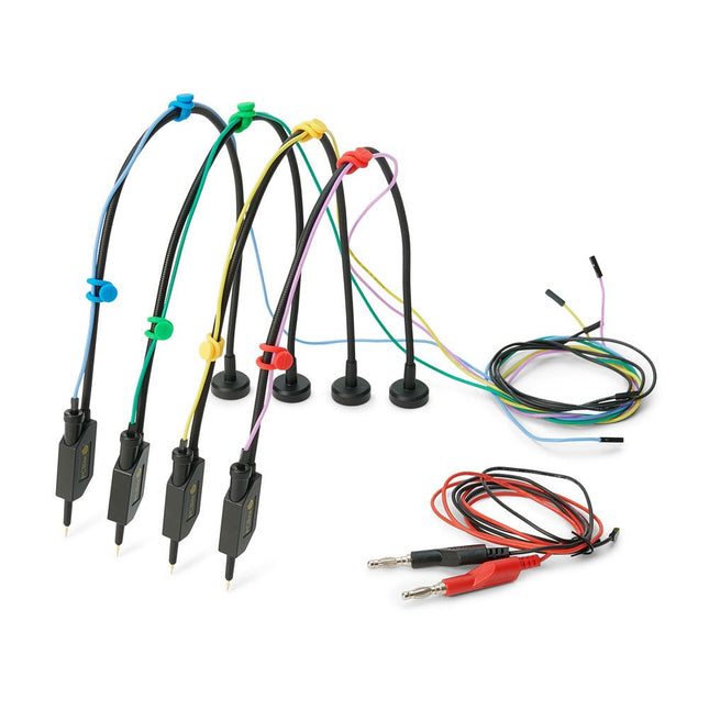
Sensepeek Sensepeek 6005 4x SQ10 Probe incl. Test Wires
The SQ series of handsfree PCBite probes from Sensepeek are insulated, come with included color-coded cable holders and have a lower point of gravity making them even more stable compared with the original SP series of probes. All the loved features of handsfree measurement, exchangeable fine pitch spring tipped test needle and the minimalistic design is maintained to make traditional sized and handheld probes obsolete. Features All handsfree probes from Sensepeek makes instant measurements or long triggering sessions a breeze. No more soldering wires to connect your probe or complicated tools to setup, just positioning the probe needle on any test point or component in the signal path and release. Saves time and frustration during development, verification and repairs. The minimalist design and the spring-loaded test needle makes it possible to simultaneously measure on fine pitch components and nearby signals. Both length and weight of the SQ probes are perfectly balanced to be used with PCBite PCB holders and base plate which is a must for handsfree function. The probe holder comes with a powerful magnet in the base, as for all PCBite probes and holders which makes the probe easy to place and reposition. The SQ series of probes can be used handheld without the probe holder as they have an insulated grip but their full potential is used when measuring handsfree. Included 4x SQ10 probes and pin tipped test needles (black) 2x Banana to dupont test wires (red/black) 5x Dupont to dupont test wires 1x Set of cable holders (4 colors) 4x Extra test needles Downloads User guide
€ 107,69
-
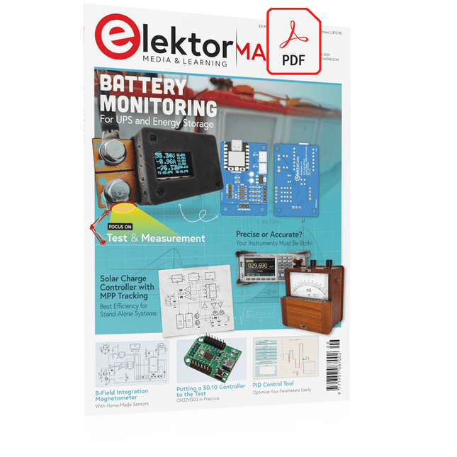
Elektor Digital Elektor May/June 2025 (PDF) EN
Elektor GREEN and GOLD members can download their digital edition here. Not a member yet? Click here. PbMonitor v1.0A Battery-Monitoring System for UPS and Energy Storage Applications Solar Charge Controller with MPPT (1)Basic Principles of a Solar Controller for Stand-Alone Systems B-Field Integration Magnetometer With Home-Made Sensors Precise or Accurate?Your Instruments Need to Be Both! AD7124 A Precision ADC in PracticeFeatures for Sensor Signal Conditioning PID Control ToolOptimize Your Parameters Easily embedded world 2025 Starting Out in Electronics……Continues with Tone Control Academy Pro BoxBook + Online Course + Hardware Milliohmmeter AdapterUses the Precision of Your Multimeter The Next Leap in SemiconductorsOnward Toward 1.4 nm Through-Hole Technology ConnectorsThe Best of Two Worlds: THR Frequency CounterPortable and Auto-Calibrating Via GPS Analog MetersPeculiar Parts, the Series Stand-Alone Crystal TesterHow Accurate Is Your Clock Source? Low-Cost I²C TesterConnect I²C Devices Directly to Your PC From Life’s ExperienceWho Doesn’t Honor the Small Things? 2025: An AI OdysseyThe Transformative Impact on Software Development Err-lectronicsCorrections, Updates, and Readers’ Letters Raspberry Pi Standalone MIDI Synthesizer (2)Enhancing Our Setup with Intelligence Nortonized Wien Bridge OscillatorSmall Changes Yield Significant Improvements Putting a $0.10 Controller to the TestThe CH32V003 RISC-V Microcontroller and MounRiver Studio in Practice An FPGA-Based Audio Player with Equalizer (2)Adding Volume Control, Advanced Mixing, and a Web Interface
€ 7,50
-
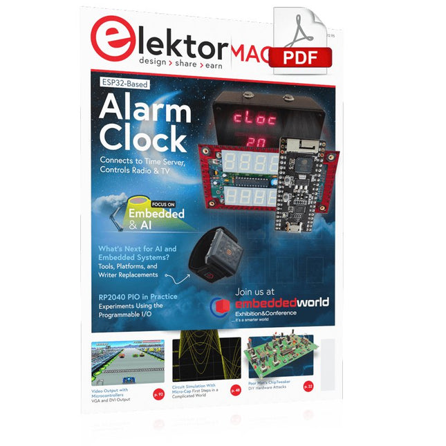
Elektor Digital Elektor March/April 2023 (PDF)
Elektor GREEN and GOLD members can download their digital edition here. Not a member yet? Click here. Cloc 2.0The Alarm Clock You've Always Wanted RP2040 PIO in PracticeExperiments Using the RP2040’s Programmable I/O Poor Man's ChipTweakerWe Have (Low-Budget) Ways of Making You Talk USB True Random Number GeneratorTwo PICs for the Price of One AVR Pimp My MicSelf-Designed Level Booster FFT with a MaixduinoFrequency spectrum display From Life’s ExperienceDesign Logic (or Non-Logic) UCN5804 Stepper Motor DriverPeculiar Parts, the Series Circuit Simulation With Micro-CapFirst Steps in a Complicated World PAUL Award 2022Young Technical Talents and Their Creative Solutions My First Software-Defined RadioBuilt in Less Than 15 Minutes Microcontroller Documentation Explained (Part 1)Datasheet structure What’s Next for AI and Embedded Systems?Tools, Platforms, and Writer Replacements Digitizing Vertical Farming Infographics: Embedded and AI Today and Tomorrow An Introduction to TinyML JetCarrier96A Versatile NVIDIA Jetson Development System Case Study: Taking EV Charging Global with a Universal RFID Solution High-Performance in Every ClassComputer-on-Module Standards Starting Out in ElectronicsLet’s Get Active! I²C Communication Using Node.js and a Raspberry PiSee Your Sensor Data in a Browser Video Output with Microcontrollers (2)VGA and DVI Output The Metronom Real-Time Operating SystemAn RTOS for AVR Processors DVI on the RP2040An Interview with Luke Wren, Chip Developer at Raspberry Pi Display HAT MiniShow the Weather Forecast on Raspberry Pi! WEEF 2022 Awards: Celebrate the Good Hexadoku
€ 7,50
-

Elektor Digital Designing Tube Amplifiers (E-book)
This book focuses more on practical aspects than on theory, and it has an contemplative nature, as though the author were viewing amplifiers from above. Knowledge elements are integrated and placed in the context of a broad overview. Even now tube amplifiers still sound great perhaps better than ever before. In part that is because we now have access to modern components such as toroidal output transformers, extremely high-quality resistors and capacitors, and many sorts of wire with good acoustic properties. Modern audio sources, such as CD players, and the latest top-end loudspeakers also enable us to appreciate how well tube amplifiers reproduce music even better than before. This new book from Menno van der Veen looks at tube amplifiers from more than just a theoretical perspective. It focuses primarily on the design phase, where decisions must be taken with regard to the purpose and requirements of the amplifier, and it addresses the following questions: How do these aspects relate to subjective and objective criteria? Which circuits sound the best, and why? If you want to develop and market an amplifier, what problems should you expect? What are the significance and meaning of measurements? Are they still meaningful, or have they lost their relevance? Thanks to the enormous processing power of computers, we can now measure more details than ever before. How can these new methods be applied to tube amplifiers? Previously it was sufficient to measure the frequency range, power and distortion of an amplifier in order to characterize the amplifier. Are these measurements still sufficient, or should we start measuring according to how we hear, using real music signals instead of waveforms from signal generators? The author sketches a future where amplifier measurements that conform to our sense of hearing enable us to arrive at new insights. This book focuses more on practical aspects than on theory, and it has an contemplative nature, as though the author were viewing amplifiers from above. Knowledge elements are integrated and placed in the context of a broad overview.
€ 29,95
Members: € 26,96
-

SDRplay SDRplay RSP1B 14-bit SDR Receiver (1 kHz to 2 GHz)
The SDRplay RSP1B is an enhanced version of the popular RSP1A – a powerful, wideband, full-featured 14-bit SDR that covers the RF spectrum from 1 kHz to 2 GHz. The RSP1B comes in a rugged, black-painted steel case and offers significantly improved noise performance. All it needs is a computer and an antenna to deliver excellent communications-receiver functionality. It includes a choice of SDRuno for Windows and the multi-platform SDRconnect software for Windows, macOS, and Linux (supplied free of charge by SDRplay). You can monitor up to 10 MHz of spectrum at a time. A documented API allows developers to create new demodulators or applications for the platform. Features Covers all frequencies from 1 kHz through VLF, LF, MW, HF, VHF, UHF and L-band to 2 GHz, with no gaps Receive, monitor and record up to 10 MHz of spectrum at a time Free use of windows-based SDRuno software which provides an ever-increasing feature-set Strong and growing software support network Calibrated S meter/ RF power and SNR measurement with SDRuno (including datalogging to .CSV file capability) Documented API provided to allow demodulator or application development on multiple platforms Excellent dynamic range for challenging reception conditions Works with popular 3rd party SDR software (including HDSDR, SDR Console and Cubic SDR) ExtIO based plugin available Software upgradeable for future standards Strong and growing software support network API provided to allow demodulator or application development Multiplatform driver and API support including Windows, Linux, Mac, Android and Raspberry Pi Up to 16 individual receivers in any 10 MHz slice of spectrum using SDRuno Calibrated S meter and power measurements with SDRuno Stand-alone windows-based spectrum analyser software available (with sweep, sample and hold features) Ideal for monitoring of ISM/ IoT/ Telemetry bands <2 GHz Ideal for portable operation Specifications Frequency Range 1 kHz – 2 GHz Antenna Connector SMA Antenna Impedance 50 Ohms Current Consumption (Typical) 185 mA (excl. Bias-T) USB Connector USB Type B Maximum Input Power +0 dBm Continuous+10 dBm Short Duration ADC Sample Rates 2-10.66 MSPS ADC Number of Bits 14 bit 2-6.048 MSPS12 bit 6.048-8.064 MSPS10 bit 8.064-9.216 MSPS8 bit >9.216 MSPS Bias-T 4.7 V100 mA guaranteed Reference 0.5ppm 24 MHz TCXO.Frequency error trimmable to 0.01ppm in field. Operating Temperature Range -10˚C to +60˚C Dimensions 98 x 88 x 34 mm Weight 110 g Downloads Datasheet Software RSP1B vs RSPdx vs RSPduo RSP1B RSPdx RSPduo Continuous coverage from 1 kHz to 2 GHz ✓ ✓ ✓ Up to 10 Mhz visible bandwidth ✓ ✓ ✓ 14-bit ADC silicon technology plus multiple high-performance input filters ✓ ✓ ✓ Software selectable AM/FM & DAB broadcast band notch filters ✓ ✓ ✓ 4.7 V Bias-T for powering external remote antenna amplifier ✓ ✓ ✓ Powers over the USB cable with a simple type B socket ✓ ✓ ✓ 50Ω SMA antenna input(s) for 1 kHz to 2 GHz operation (software selectable) 1 2 2 Additional software selectable Hi-Z input for up to 30 Mhz operation ✓ Additional software selectable 50Ω BNC input for up to 200 MHz operation ✓ Additional LF/VLF filter for below 500 kHz ✓ 24 MHz reference clock input (+ output on RSPduo) ✓ ✓ Dual tuners enabling reception on 2 totally independent 2 MHz ranges ✓ Dual tuners enabling diversity reception using SDRuno ✓ Robust and strong plastic case (with internal RF shielding layer) ✓ Rugged black painted steel case ✓ ✓ Overall performance below 2 MHz for MW and LF + ++ + Multiple simultaneous applications + + ++ Performance in challenging fading conditions (*using diversity tuning) + + *++
€ 148,99
-

Elektor Digital The BeagleY-AI Handbook (E-book)
A Practical Guide to AI, Python, and Hardware Projects Welcome to your BeagleY-AI journey! This compact, powerful, and affordable single-board computer is perfect for developers and hobbyists. With its dedicated 4 TOPS AI co-processor and a 1.4 GHz Quad-core Cortex-A53 CPU, the BeagleY-AI is equipped to handle both AI applications and real-time I/O tasks. Powered by the Texas Instruments AM67A processor, it offers DSPs, a 3D graphics unit, and video accelerators. Inside this handbook, you‘ll find over 50 hands-on projects that cover a wide range of topics—from basic circuits with LEDs and sensors to an AI-driven project. Each project is written in Python 3 and includes detailed explanations and full program listings to guide you. Whether you‘re a beginner or more advanced, you can follow these projects as they are or modify them to fit your own creative ideas. Here’s a glimpse of some exciting projects included in this handbook: Morse Code Exerciser with LED or BuzzerType a message and watch it come to life as an LED or buzzer translates your text into Morse code. Ultrasonic Distance MeasurementUse an ultrasonic sensor to measure distances and display the result in real time. Environmental Data Display & VisualizationCollect temperature, pressure, and humidity readings from the BME280 sensor, and display or plot them on a graphical interface. SPI – Voltmeter with ADCLearn how to measure voltage using an external ADC and display the results on your BeagleY-AI. GPS Coordinates DisplayTrack your location with a GPS module and view geographic coordinates on your screen. BeagleY-AI and Raspberry Pi 4 CommunicationDiscover how to make your BeagleY-AI and Raspberry Pi communicate over a serial link and exchange data. AI-Driven Object Detection with TensorFlow LiteSet up and run an object detection model using TensorFlow Lite on the BeagleY-AI platform, with complete hardware and software details provided.
€ 34,95
Members: € 31,46
-
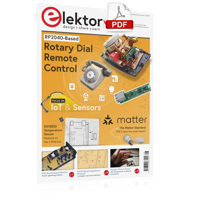
Elektor Digital Elektor July/August 2023 (PDF)
Elektor GREEN and GOLD members can download their digital edition here. Not a member yet? Click here. Rotary Dial Phone as Remote ControlTo Switch On the Lights, Dial 1; For the Coffee Maker, Dial 2 GPS-Based Speed MonitorNo More Speeding Tickets RGB Stroboscope with ArduinoA Colorful Adaptation of a Useful Instrument Wireless Emergency Push ButtonEnhanced Safety with LoRa Starting Out in ElectronicsFollow the Emitter Arbitrary, Independent Hysteresis Levels for Comparatorswith Simulations, Spreadsheets and Algebra ESP32-Based Impedance AnalyzerSimple, Low-Part-Count, and Inexpensive! HomeLab ToursEncouraging DIY The MCCAB Arduino Nano Training BoardAll-in-One Hardware for the “Microcontrollers Hands-On Course” From Life’s ExperienceModern Luddism Sensor 101: The DS18B20 Temperature SensorConnection to the 1-Wire Bus Is Matter the Thread to Save the Smart Home?New Standards to Simplify the Smart Home A Matter of CollaborationDeveloping with the Thing Plus Matter Board and Simplicity Studio Infographics: IoT and Sensors Matter, ExpressLink, Rainmaker — What Is This All About?Q&A with Amey Inamdar, Technical Marketing Director at Espressif Selecting Microcontroller Dev Kits for IoT and IIoT ApplicationsAn Introductory Guide Capacitors Do Not Always Behave Capacitively! An NTP Clock with CircuitPythonWhy Should You Use This Programming Language? Build a Cool IoT DisplayWith the Phambili Newt The HB100 Doppler Motion SensorTheory and Practice A Bare-Metal Programming Guide (Part 1)For STM32 and Other Controllers Siglent SDM3045X Multimeter Microprocessors for Embedded SystemsPeculiar Parts, the Series Microcontroller Documentation Explained (Part 3)Block Diagrams and More Low-Power LoRa Weather StationBuild a long-range weather station by yourself Transverter for the 70 cm Band Climate Calling EngineersMove Fast and Fix Things Hexadoku
€ 7,50
-
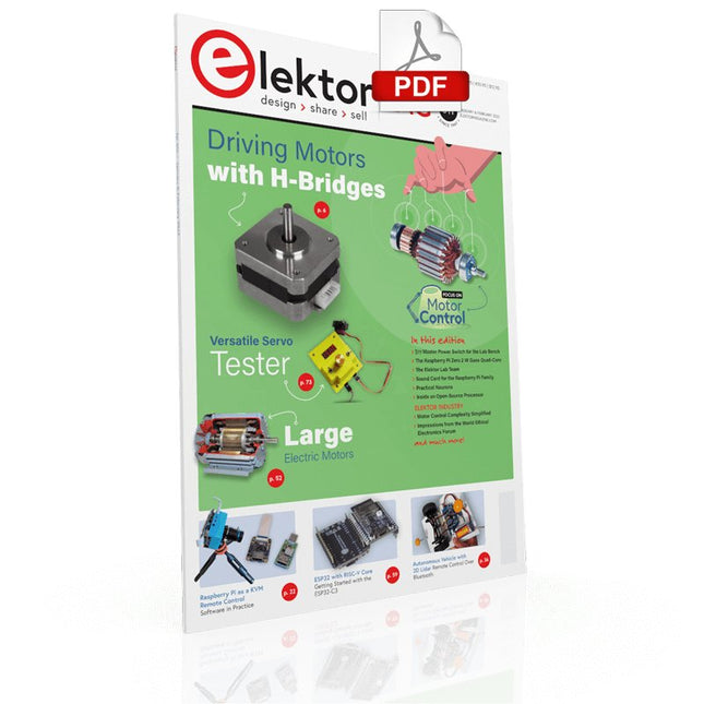
Elektor Digital Elektor January/February 2022 (PDF)
DRIVING MOTORS WITH H-BRIDGESAn Introduction to DC, Stepper, and Brushless Motors THE ELEKTOR LAB TEAMOur Approach, Preferred Tools, and More RASPBERRY PI AS A KVM REMOTE CONTROLPi-KVM Software Test IQAUDIO CODEC ZEROA Sound Card for the Raspberry Pi Family THE PIKVM PROJECT AND LESSONS LEARNEDInterview with Maxim Devaev (Developer, PiKVM) AUTONOMOUS VEHICLE WITH 2D LIDARESP32 Pico Interprets Data from the Lidar Module THE RASPBERRY PI ZERO 2 W GOES QUAD-CORE NOTES FROM THE 2021 WORLD ETHICAL ELECTRONICS FORUM MOTOR CONTROLHow the Complexity of Motor Control Is Simplified LARGE ELECTRIC MOTORSBasic Principles and Useful Information GETTING STARTED WITH THE ESP32-C3 RISC-V MCU PROTECT YOURSELF AND OTHERS!DIY Master Power Switch for the Lab Bench CREATE GUIS WITH PYTHON (PART 2)Spy name chooser PRODUCTRONICA FAST FORWARD 2021 WINNERSExciting Technologies and Creative Engineering Solutions VERSATILE SERVO TESTERCheck Behavior When There’s No Datasheet MODBUS OVER WLAN (PART 2)Software for the Modbus TCP WLAN Module UNDERSTANDING THE NEURONS IN NEURAL NETWORKS (PART 3)Practical Neurons INSIDE AN OPEN-SOURCE PROCESSORSample Chapter: Lattice and Xilinx FPGA Results STARTING OUT IN ELECTRONICSWe Are Not Yet Done with the Coil ERR-LECTRONICSCorrections, Updates and Readers’ Letters COLOR TO SOUNDHow to Read Out a Color Sensor via I2C BATTLAB-ONEMeasure and Optimize the Battery Life of IoT Devices SIMPLE EARTH-LEAKAGE TRACERTesting Isolation of Mains Supply POVERTY AND ELECTRONICSSustainable Development Goal 1 HEXADOKUThe Original Elektorized Sudoku
€ 7,50
-
Raspberry Pi Foundation FPC Display Cable for Raspberry Pi 5 (300 mm)
Raspberry Pi 5 provides two four-lane MIPI connectors, each of which can support either a camera or a display. These connectors use the same 22-way, 0.5 mm-pitch “mini” FPC format as the Compute Module Development Kit, and require adapter cables to connect to the 15-way, 1 mm-pitch “standard” format connectors on current Raspbery Pi camera and display products.These mini-to-standard adapter cables for cameras and displays (note that a camera cable should not be used with a display, and vice versa) are available in 200 mm, 300 mm and 500 mm lengths.
€ 2,95€ 1,18Best Price
-
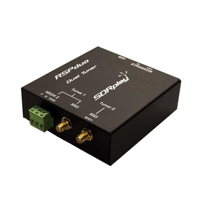
SDRplay SDRplay RSPduo Dual-Tuner 14-bit SDR Receiver (1 kHz to 2 GHz)
The SDRplay RSPduo is a high performance dual-tuner 14-bit SDR receiver. Housed in a high quality steel enclosure, each tuner can operate individually anywhere between 1 kHz and 2 GHz with up to 10 MHz of bandwidth or both tuners can operate simultaneously anywhere between 1 kHz and 2 GHz with up to 2 MHz of bandwidth per tuner. A high stability reference along with external clocking features makes this device ideally suited to industrial, scientific & educational applications. Features Dual tuner provides independent coverage from 1 kHz to 2 GHz using 2 antenna ports simultaneously 14-bit ADC silicon technology Up to 10 MHz visible bandwidth (single tuner mode) or 2 slices of 2 MHz spectrum (dual tuner mode) 3 software-selectable antenna ports (2x 50Ω and 1x 1kΩ high impedance balanced/unbalanced input) High impedance antenna port (1 kHz to 30 MHz) with selectable MW notch filter and choice of 2 pre-selection filters Software selectable AM/FM and DAB broadcast band notch filters for the 2 SMA antenna (1 kHz to 2 GHz) antenna ports External clock input and output enables easy synchronisation to multiple RSPs or external reference clock Powers over the USB cable with a simple type B socket 11 high-selectivity, built in front-end preselection filters on both the 2 SMA antenna ports Software selectable multi-level Low Noise Preamplifier Bias-T power supply for powering antenna-mounted LNA Enclosed in a rugged black painted steel case. SDRuno – World Class SDR software for Windows Documented API for new apps development Specifications Frequency Range 1 kHz – 2 GHz Antenna Connector SMA Antenna Impedance 50 Ohms Current Consumption (Typical) Single Tuner Mode: 180 mA (excl. Bias-T)Dual Tuner Mode: 280 mA (excl. Bias-T) USB Connector USB-B Maximum Input Power +0 dBm Continuous+10 dBm Short Duration ADC Sample Rates 2-10.66 MSPS ADC Number of Bits 14 bit 2-6.048 MSPS12 bit 6.048-8.064 MSPS10 bit 8.064-9.216 MSPS8 bit >9.216 MSPS Bias-T 4.7 V100 mA guaranteed Reference High Temperature Stability (0.5ppm) 24 MHz TCXO.Frequency error trimmable to 0.01ppm in field. Operating Temperature Range −10˚C to +60˚C Dimensions 98 x 94 x 33 mm Weight 315 g Downloads Datasheet Detailed Technical Information Software RSPdx-R2 vs RSPduo RSPdx-R2 RSPduo Continuous coverage from 1 kHz to 2 GHz ✓ ✓ Up to 10 MHz visible bandwidth ✓ ✓ 14-bit ADC silicon technology plus multiple high-performance input filters ✓ ✓ Software selectable AM/FM & DAB broadcast band notch filters ✓ ✓ 4.7 V Bias-T for powering external remote antenna amplifier ✓ ✓ Powers over the USB cable with a simple type B socket ✓ ✓ 50Ω SMA antenna input(s) for 1 kHz to 2 GHz operation (software selectable) 2 2 Additional software selectable Hi-Z input for up to 30 Mhz operation ✓ Additional software selectable 50Ω BNC input for up to 200 MHz operation ✓ Additional LF/VLF filter for below 500 kHz ✓ 24 MHz reference clock input (+ output on RSPduo) ✓ ✓ Dual tuners enabling reception on 2 totally independent 2 MHz ranges ✓ Dual tuners enabling diversity reception using SDRuno ✓ Rugged black painted steel case ✓ ✓ Overall performance below 2 MHz for MW and LF ++ + Multiple simultaneous applications + ++ Performance in challenging fading conditions (*using diversity tuning) + *++
€ 287,98
-

Elektor Digital BBC micro:bit (E-book)
35 Touch Develop & MicroPython Projects The BBC micro:bit is a credit sized computer based on a highly popular and high performance ARM processor. The device is designed by a group of 29 partners for use in computer education in the UK and will be given free of charge to every secondary school student in the UK. The device is based on the Cortex-M0 processor and it measures 4 x 5 cm. It includes several important sensors and modules such as an accelerometer, magnetometer, 25 LEDs, 2 programmable push-button switches, Bluetooth connectivity, micro USB socket, 5 ring type connectors, and a 23-pin edge connector. The device can be powered from its micro USB port by connecting it to a PC, or two external AAA type batteries can be used. This book is about the use of the BBC micro:bit computer in practical projects. The BBC micro:bit computer can be programmed using several different programming languages, such as Microsoft Block Editor, Microsoft Touch Develop, MicroPython, and JavaScript. The book makes a brief introduction to the Touch Develop programming language and the MicroPython programming language. It then gives 35 example working and tested projects using these language. Readers who learn to program in Touch Develop and MicroPython should find it very easy to program using the Block Editor or any other languages. The following are given for each project: Title of the project Description of the project Aim of the project Touch Develop and MicroPython program listings Complete program listings are given for each project. In addition, working principles of the projects are described briefly in each section. Readers are encouraged to go through the projects in the order given in the book.
€ 24,95
Members: € 22,46
-
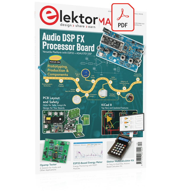
Elektor Digital Elektor November/December 2024 (PDF)
Elektor GREEN and GOLD members can download their digital edition here. Not a member yet? Click here. Audio DSP FX Processor BoardPart 1: Features and Design 50 Years of Elektor in English KiCad 8Top New and Updated Features Elektor MultiCalculator KitAn Arduino-Based Calculator Kit for Electronic Purposes Low-Cost GNSS RTK SystemsWith Centimeter-Level Degree of Accuracy PCB Layout and SafetyHints for a Safe, Long-Life Design of Your Boards Opamp TesterFor Audio and Other Applications Project Update #4: ESP32-Based Energy MeterEnergy Monitoring with MQTT Real-Time Spectrum Analyzer with Waveguide Technology and Multi-Interface PCsAaronia Establishes New Product Segment and Presents First Prototypes at Electronica in Munich Applications of Ynvisible’s E-paper DisplaysTransform Businesses and Shape the Future SMT InductorsCoils and Ferrites — Selection Made Easy Arrow Electronics to Showcase Innovative Technologies at electronica 2024 Using EMI Shielding to Achieve Electromagnetic Compatibility Compliance The Ultimate Tool for Every Electronics EnthusiastUnlock Endless Possibilities with Red Pitaya and 1,000+ Click Boards™ V-LD1 Distance Radar Module Siglent Presents Its New Vector Network Analyzer Platform SNA6000A HDI in the MiddleA New Cost-Effective PCB Pooling Service for Tiny BGAs Remote Access IoT LabOne and Only Solution for Remote Learning and Development in Embedded Industry Challenges of DFM Analysis for Flex and Rigid-Flex Design From Life's ExperienceMicrotechnophobia 3D Christmas TreeA 3D PCB with a Low-Cost, 32-bit Microcontroller Starting Out in Electronics……Continues with the Opamp! An Autonomous Sensor Node (Project Update #1)Reducing Idle Power Consumption with External RTC and Power Switch 2024: An AI OdysseyA Look Back at the Future LED Displays with the MAX7219A Hands-On Approach to a Great Chip Err-lectronicsCorrections, Updates, and Readers’ Letters VibroTactile GlovesA Breakthrough for Parkinson’s Patients
€ 7,50
-

Elektor Publishing Arduino UNO Q and AI
Learn to Build Intelligent Embedded Systems Build smarter embedded systems with Arduino UNO Q. This book gives you the tools, knowledge, and confidence to turn ideas into intelligent, working solutions using the Arduino UNO Q platform. Discover how to build intelligent embedded systems with the Arduino UNO Q and AI. Unlock the full potential of the Arduino UNO Q, a next-generation platform that combines the real-time power of the STM32U585 microcontroller with the flexibility of a Qualcomm Dragonwing QRB2210 microprocessor. Learn how to rapidly prototype real-world applications using the Arduino IDE for low-level embedded control and Python in Arduino App Lab for high-level development. Build confidence through hands-on projects that guide you step by step from basic board features to complete working systems. Explore ready-to-use, AI based Arduino App Lab examples and see how they can jump-start your development and reduce time to deployment. Step into the world of Edge AI with a clear, practical introduction to Edge Impulse Studio—no prior AI experience required. Follow a complete, real-world workflow to create a Keyword Spotting AI application, covering data collection, model training, optimization, and on-device inference using the Edge Impulse Studio. Bridge the gap between embedded systems and machine learning and learn how to bring intelligence directly onto your hardware. Perfect for embedded engineers, educators, students, and makers looking to stay ahead in AI-enabled product development.
€ 34,95
Members: € 31,46
-
Elektor Digital Elektor July/August 2021 (PDF)
Elektor Magazine EN July/August 2021 (PDF)
€ 7,50
-

Elektor Publishing Experimenting with Red Pitaya STEMlab Gen 2
Practical Projects and Programs With Experimenting with Red Pitaya STEMlab Gen 2, Red Pitaya goes beyond a versatile board. It becomes a powerful laboratory instrument for precision measurement, analysis, and control. From the fundamentals of electronic project development, monitoring, control, and design to testing, this book walks you step-by-step through everything you need to know to harness the full potential of Red Pitaya hardware and software. The book presents real-time, FPGA-based projects that are developed on a PC using the Vivado environment, then transferred to the Red Pitaya for execution and testing. You will learn about enhanced performance, expanded I/O capabilities, improved FPGA features, and advanced connectivity options that open up new frontiers for precision measurement, monitoring, and control in your embedded applications. Inside the book you will discover: A deep dive into Red Pitaya architecture and hardware design Electronic experiments using Red Pitaya for measurement and monitoring Hands-on projects using the Python programming language Practical guidance for FPGA programming using Red Pitaya Red Pitaya FPGA projects using the Verilog HDL under Vivado IDE Practical design of electronic projects including measurement and testing Step-by-step examples that bridge theory and real-world implementation Whether you are designing your own electronic circuits, developing signal analysis tools, or creating real-time control or monitoring systems, this book provides you the knowledge and confidence you need to fully learn and customize the Red Pitaya platform.
€ 39,95€ 32,95Best Price


