Bestsellers
-
Elektor Digital IoT Home Hacks with ESP8266 (E-book)
There are many so-called 'Arduino compatible' platforms on the market. The ESP8266 – in the form of the WeMos D1 Mini Pro – is one that really stands out. This device includes WiFi Internet access and the option of a flash file system using up to 16 MB of external flash memory. Furthermore, there are ample in/output pins (though only one analogue input), PWM, I²C, and one-wire. Needless to say, you are easily able to construct many small IoT devices! This book contains the following builds: A colourful smart home accessory refrigerator controller 230 V power monitor door lock monitor and some further spin-off devices. All builds are documented together with relevant background information for further study. For your convenience, there is a small PCB for most of the designs; you can also use a perf board. You don’t need to be an expert but the minimum recommended essentials include basic experience with a PC, software, and hardware, including the ability to surf the Internet and assemble PCBs. And of course: A handle was kept on development costs. All custom software for the IoT devices and PCB layouts are available for free download from at Elektor.com.
€ 34,95
Members: € 31,46
-

Elektor Publishing The Connected Autonomous Vehicle and its Environment
An Introduction to Real and Reduced-Scale Autonomous Vehicles Want to cut through the hype and get to the core of autonomous and connected vehicles? Then this book is your clear, accessible guide to a complex and fast-moving field. Starting with Intelligent Transport Systems (ITS), it walks you through the essential foundations, including Advanced Driver Assistance Systems (ADAS) – the stepping stones to full autonomy. Explore how self-driving cars mimic human behavior through a loop of perception, analysis, decision, and action. Discover the key functions that make it possible: localization, obstacle detection, driver monitoring, cooperative awareness – and the most challenging of all, trajectory planning, across strategic, tactical, and operational levels. Will vehicles be connected? The debate is on – but the standards are already here. Learn how connectivity, infrastructure, and vehicles can work in synergy through the innovative concept of floating car data (FCD). Dive into real-world implementation: with embedded electronics account-ing for over 30% of a modern vehicle‘s cost, we unpack the architecture, coordination, and tools required to manage the complexity – brought to life with a hands-on case study. To finish, we open the door to the future: building your own 1:10 scale autonomous vehicle. No plug-and-play solutions – just the foundations for a collaborative, creative, and geek-friendly challenge. Let’s drive the future together.
€ 34,95
Members: € 31,46
-
Elektor Digital Elektor Special: Solar Power Systems and Photovoltaics (PDF)
As demand for solar panel installation has risen sharply, especially for installations larger than balcony power plants, the order books of solar companies are full. If you ask for a quote today, you may have to wait a while, if your request isn't simply postponed indefinitely. Another consequence of the solar boom is that some companies are charging very high prices for installations. Yet there is an obvious and radical solution to the problem of excessive prices: Do it yourself, as the English say. The price of materials is currently affordable, and it's the ideal time for those who do the work themselves. They couldn't save more. Add to this the satisfaction of doing something useful, both economically and ecologically, and the pleasure of building yourself. In this special issue, you'll find a wide selection of Elektor assemblies, from solar panel controllers to solar water heaters and solar panel orientation systems. The issue also contains practical information on solar panel installation and the technology behind them. Finally, there are a number of articles on the subject of balcony power plants, from how to install them to how to connect them to the Internet... Contents BASICS Dimensioning Photovoltaic Panel ArraysAn introduction to photovoltaic energy and the commonest techniques,followed by simplified calculation models and setup guidelines. Light Sensor TechnologyMeasuring daylight using LEDs. Solar Power Made SimpleSolar charging with and without a controller. Cable Cross-sections and Energy Losses in Solar SystemsKey considerations on the minimum values to respect for electricalcurrent in solar panel cabling. Solar ModulesEverything you always wanted to know about solar panels... Ideal Diode ControllerDiode Circuits with Low Power Dissipation. TIPS Tracking for Solar Modules zBot Solar/Battery Power Supply Solar Cell Array Charger with Regulator Solar Cell Voltage Regulator Solar-Powered Night Light Alternative Solar Battery Charger PROJECTS Energy LoggerMeasuring and Recording Power Consumption. Tiny Solar SupplySunlight In, 3.3 V Out. A Do-It-Yourself DTURead Data from Small Inverters by μC. Solar ChargerPortable energy for people on the move. Solar Thermal Energy RegulatorMaximum power point tracking explored. 2-amp Maximum Power Tracking ChargerSolar Power To The Max. Computer-driven HeliostatFollow the sun or the stars. Garden LightingUsing solar cells. Solar Panel Voltage Converter for IoT DevicesYes we CAN exploit indoor lighting. Travel ChargerFree power in the mountains. Solar Cell Battery Charger/MonitorWith protection against deep discharge. Solar-powered Battery ChargerPIC12C671 avoids overcharging and deep charging. Converters for Photovoltaic PanelsContributed by TME (Transfer MultisortElektronik). Solar Charging RegulatorFor panels up to 53 watts. Solar-Powered ChargerFor lead-acid batteries. CAN Bus + Arduino for Solar PV Cell MonitoringDetect and locate serviceable panels in large arrays. Balcony Power Plant 2.0The latest: solar panels, installation and inverters
€ 14,95
Members: € 13,46
-

Great Scott Gadgets Acrylic Case for HackRF SDR
This clear acrylic case is the official case for the HackRF One/Pro board. It can replace the standard black plastic case of the HackRF One/Pro. Assembly Instructions Use a guitar pick or spudger to extract the HackRF One/Pro circuit board from the black plastic case. Insert one long screw into each corner of the bottom acrylic panel. Secure each long screw with a short (5 mm) spacer on the opposite side of the panel. Place the HackRF One/Pro circuit board (facing up) on top of the bottom panel, fitting the ends of the long screws through the corner mounting holes of the circuit board. Secure the circuit board with one long (6 mm) spacer in each corner. Place the top acrylic panel on top of the circuit board, aligning the cutouts with the circuit board’s expansion headers. Secure each corner with a short screw. Note: Do not overtighten! Hand-tighten only at every step.
€ 19,95
Members: € 17,96
-

Andonstar Andonstar ADSM302 5" HDMI Digital Microscope
The Andonstar ADSM302 is a versatile digital microscope with an integrated 5-inch LCD display and HDMI output for crystal-clear views in Full HD (1080p). With a 3-megapixel sensor, up to ~560x magnification, and two adjustable LED lights, it reveals the finest details – ideal for PCB inspections, soldering work, jewelry or insect analysis. Features 5" adjustable LCD monitor with adjustable tilt angle High resolution video & photo capture Wide table with comfortable headroom Heavy-weight stable metal stand Tall lifting stand (26 cm) Smooth adjustment wheels for focus and height Buttons on the monitor + remote control AV, USB, HDMI outputs SD card storage <32 GB Specifications Image sensor 3 Megapixels HD Sensor Video output 1080p Full HD (via HDMI)720p (via PC) Video format Real time play via HDMI w/o recordingMJPEG recording via PC/Mac Software Magnification Up to 560 times (HDMI monitor 22") Photo resolution 12M (see pixel formats in following table) Photo format JPEG Focus range 5 to 22 cm Frame rate Up to 30 f/s under 600 Lux Brightness Video-output interface HDMI/AV Storage microSD card, up to 32 GB PC support Windows XP/7/8/10PC software with measurementMacOS successfully tested under OSX with OBSsee video below Power source 5 V DC Light source 2x LED with the stand Screen size 5 inch (12.7 cm) Stand size 20 x 12 x 26.5 cm Resolution Captured Photos 4032 x 3024 3648 x 2736 3264 x 2448 2592 x 1944 2048 x 1536 640 x 480 1920 x 1080 1280 x 960 1280 x 720* Videos 1920 x 1080 640 x 480* * (USB with software) Included 1x Andonstar ADSM302 digital microscope 1x Metal stand with 2 LEDs 1x USB cable 1x HDMI cable 1x Adapter 1x AI remote 1x Instructions Downloads Manual Software
€ 199,00
-

Elektor Digital Assembly Language Essentials (E-book)
A Guide to Powerful Programming for Embedded Systems You must be a well-rounded professional to excel in the ever-evolving, rapidly developing embedded design and programming industry. Simply put, when it comes to electronics design and programming, the more topics you can master, the more you’ll flourish at your workplace and at your personal workbench. This shouldn’t be a surprise, as the line between the skills of a hardware engineer and software engineer is blurring. The former should have a good grasp of programming in order to build efficient systems. The latter should understand the details of the design (whether it’s a physical or virtual application) for which he or she is writing code. Thus, to be successful, a modern professional electronics engineer must have a solid grasp of both hardware design and programming. Assembly Language Essentials is a matter-of-fact guide to Assembly that will introduce you to the most fundamental programming language of a processor. Unlike other resources about Assembly that focus exclusively on specific processors and platforms, this book uses the architecture of a fictional processor with its own hardware and instruction set. This enables you to consider the importance of Assembly language without having to deal with predetermined hardware or architectural restrictions. You’ll immediately find this thorough introduction to Assembly to be a valuable resource, whether you know nothing about the language or you have used it before. The only prerequisite is that you have a working knowledge of at least one higher-level programming language, such as C or Java. Assembly Language Essentials is an indispensible resource for electronics engineering professionals, academics, and advanced students looking to enhance their programming skills. The book provides the following, and more: An introduction to Assembly language and its functionality Significant definitions associated with Assembly language, as well as essential terminology pertaining to higher-level programming languages and computer architecture Important algorithms that may be built into high-level languages, but must be done the “hard way” in Assembly language — multiplication, division, and polynomial evaluation A presentation of Interrupt Service Routines with examples A free, downloadable Assembler program for experimenting with Assembly
€ 29,95
Members: € 26,96
-
Elektor Digital Electronics for Space (E-book)
Space, the final frontier, will become more and more popular. The space industry is continually growing and new products and services will be required. Innovation is needed for the development of this industry. Today it is no longer possible to follow all the events in field of space. The space market is growing and activities are increasing, especially the market for small-satellites. This book wants to help close the gap and encourage electronic engineers to enter into the fascinating field of space electronics. One of the main difficulties is finding people with knowledge of space electronics design. Nowadays companies have to invest a lot of time and resources to instruct electronic engineers with no experience of space. Only a brief and basic introduction of this topic is typically achieved at university in space engineering lectures. Professionals with practical experience and the necessary theoretical knowledge are scarce. Companies from the space sector are searching for staff with knowledge of space electronics. This book will bring space closer aspiring to the space electronic hobbyists.
€ 24,95
Members: € 22,46
-

Elektor Digital Learning Digital Electronics (E-book)
With 20+ Practical Projects in Logic and Circuit Design This book is a practical guide to digital electronics, covering the essential components of modern digital systems: number systems, logic gates, Boolean algebra, combinational and sequential logic, and more. Through more than 20 structured projects, you’ll design and build digital systems using real-world components such as logic gates, multiplexers, decoders, flip-flops, counters, and shift registers. The projects range from basic LED logic circuits to digital locks, display systems, traffic light controllers, and timing-based designs. Selected projects introduce the use of tools such as CircuitVerse for circuit simulation, while several designs make use of 74HC-series logic devices, commonly used in digital hardware prototyping. Inside, you’ll find: Clear coverage of number systems and binary arithmetic Logic gate fundamentals and universal gate implementations Step-by-step projects using flip-flops, counters, and registers Real-world design with 74HC-series logic chips Techniques for designing combinational and sequential systems This book takes a design-first, application-driven approach to digital electronics—built around working circuits, tested logic, and hands-on experimentation.
€ 24,95
Members: € 22,46
-

Elektor Bundles Learn Edge AI with Raspberry Pi
This hands-on bundle lets you build real Edge AI applications with the Raspberry Pi Raspberry Pi AI HAT+ (13 TOPS) The Raspberry Pi AI HAT+ (13 TOPS) is an expansion board designed for the Raspberry Pi 5, featuring an integrated Hailo AI accelerator. This add-on offers a cost-effective, efficient, and accessible approach to incorporating high-performance AI capabilities, with applications spanning process control, security, home automation, and robotics. The AI HAT+ connects via the Raspberry Pi 5’s PCIe Gen3 interface. When the Raspberry Pi 5 is running a current version of the Raspberry Pi OS, it automatically detects the onboard Hailo accelerator, making the neural processing unit (NPU) available for AI tasks. Additionally, the rpicam-apps camera applications included in Raspberry Pi OS seamlessly support the AI module, automatically using the NPU for compatible post-processing functions. Raspberry Pi Camera Module 3 Raspberry Pi Camera Module 3 is a compact camera from Raspberry Pi. It offers an IMX708 12-megapixel sensor with HDR, and features phase detection autofocus. Camera Module 3 is available in standard and wide-angle variants, both of which are available with or without an infrared cut filter. Camera Module 3 can be used to take full HD video as well as stills photographs, and features an HDR mode up to 3 megapixels. Its operation is fully supported by the libcamera library, including Camera Module 3’s rapid autofocus feature: this makes it easy for beginners to use, while offering plenty for advanced users. Camera Module 3 is compatible with all Raspberry Pi computers. Book: Edge AI Made Practical – AI Projects for the Raspberry Pi with the AI HAT+ Edge AI is transforming everyday devices by putting intelligence where it matters most: directly inside the hardware. With on-device inference, a camera can recognize a visitor instantly, a phone can translate speech without streaming audio to the cloud, and a wearable can detect anomalies in real time—fast, private, and reliable even when the network disappears. This book is your practical guide to building exactly those kinds of systems with the Raspberry Pi AI HAT+ and the Hailo-8L accelerator. You’ll start with clear foundations: core AI and machine-learning concepts, how neural networks work, and what truly distinguishes Edge AI from cloud AI—plus an honest look at ethical considerations and future impacts. This bundle contains: Book: Edge AI Made Practical Raspberry Pi AI HAT+ (13 TOPS) Raspberry Pi Camera Module 3 Active Cooler for Raspberry Pi 5 FPC Display Cable for Raspberry Pi 5 (300 mm) Elektor Component Kit 40-pin GPIO Header Traffic Light Module LED red 5 V with built-in resistor LED yellow 5 V with built-in resistor LED green 5 V with built-in resistor LED blue 5 V with built-in resistor Breadboard (400 Tie-points) 10 Dupont wires male-female DHT22 sensor module Servo motor Required Raspberry Pi 5
€ 169,95
Best Price
-

JOY-iT Joy-Pi Advanced Development Platform (incl. Raspberry Pi 4, 8 GB)
For a limited time, the Joy-Pi Advanced is available in a great-value bundle with a Raspberry Pi 4 (8 GB)! The Joy-Pi Advanced is a compact and powerful device that allows you to realize your projects quickly and easily. Whether you already have a lot of experience, or next to none, the Joy-Pi Advanced lets you unleash your creativity. Thanks to its compatibility with a wide range of platforms, including Raspberry Pi, Raspberry Pi Pico, Arduino Nano, BBC micro:bit, and NodeMCU ESP32, you can easily and quickly access your preferred platform. In addition, the Joy-Pi Advanced features more than 30 stations, lessons, and modules, giving you an unlimited variety of ways to get your projects done. With the self-developed learning center, you can not only improve your skills but also create new projects. The learning center offers a wealth of information and tutorials that will guide you step by step through your projects. Joy-Pi Advanced is characterized in particular by its intelligent switch units, which allow an extended use of the available pins. A total of three switch units are integrated, each equipped with 12 individual switches that provide precise control of the connected sensors and modules. This system solves the well-known problem of limited pin count that occurs with conventional microcontrollers. The switch units allow you to operate a large number of sensors and modules in parallel by switching them on and off individually. This simulates multiple pin assignment, allowing you to exploit the full power of your projects without compromising functionality. By combining innovative adapter boards and the micro:bit slot, you can achieve seamless compatibility with a wide range of microcontrollers such as Raspberry Pi Pico, NodeMCU ESP32, micro:mit and Arduino Nano. The specially developed adapter boards are designed to perfectly match the respective microcontroller. By plugging the microcontroller onto the appropriate adapter board and then plugging it into the micro:bit slot, the Joy-Pi Advanced quickly and easily becomes compatible with the different microcontrollers. This allows seamless integration of your preferred platform and the ability to combine the strengths of the different microcontrollers in your projects. This way, you can fully focus on your creative projects without worrying about the compatibility of different microcontrollers. The Joy-Pi Advanced simplifies the development process and gives you the possibility to design your projects flexibly and individually. Features Highly integrated development platform & learning center Fast, easy & wireless combination of various sensors & actuators Installation option for Raspberry Pi 4 Compatible with various microcontrollers Self-developed, didactic learning platform for Raspberry Pi & Windows Specifications Compatible to Raspberry Pi 4, Arduino Nano, NodeMCU ESP32, BBC micro:bit, Raspberry Pi Pico Installed sensors, actuators & components 39 Learning platform Over 40 entries in the know-ledge database, 10 projects, 10 learning tasks, 14 visions Displays 7-segment display, 16x2 display, 1.8“ TFT display, 0.96" OLED display, 8x8 RGB matrix Sensors DS18B20, shock sensor, hall sensor, barometer, sound sensor, gyroscope, PIR sensor, Light barrier, NTC, Light sensor, 6x touch sensor, color sensor, ultrasonic distance sensor, DHT11 temperature & humidity sensor Control Joystick, 5x switches, potentiometer, rotary encoder, 4x4 button matrix, relays, PWM fan Motors Servo interface, Stepper motor interface, Vibration motor Measuring & conversion modules Analog-Digital Converter, Level converter, voltmeter, Variable voltage supply Other components RTC real time clock, buzzer, EEPROM memory, infrared receiver, breadboard, RFID reader Adapter boards Adapter for NodeMCU ESP32, Arduino Nano & Raspberry Pi Pico, Board connectors for Raspberry Pi & External Boards Electronic components Infrared remote control, RFID chip, RFID card, 6x alligator clips, microSD card reader, servo motor, stepper motor, 32 GB microSD card Components 40x resistors, 3x green LEDs, 3x yellow LEDs, 3x red LEDs, 1x transistor, 5x buttons, 1x potentiometer, 2x capacitors Other accessories Screw assortment, screwdriver, accessory storage bag, power supply & power cable, servo mount Power supply Built-in power supply: 36 W, 12 V, 3 A Case connector: Small device plug C8 Voltage outputs 12 V, 5 V, 3.3 V, Variable voltage output (2-11 V) Data buses & signal outputs I²C, SPI, Analog to digital converter Battery (RTC) CR2032 Dimensions 327 x 200 x 52 mm Included Raspberry Pi 4 (8 GB RAM) Downloads Joy-Pi website Datasheet Manual
€ 519,00€ 419,00Best Price
-

Elektor Digital Arduino 8-bit Sound Generation (E-book)
Arduinonext is an initiative powered by an electronics and microcontrollers specialist team aiming to help all those who are entering in the technology world, using the well-known Arduino platform to take the next step in electronics. We strive to bring you the necessary knowledge and experience for developing your own electronics applications; interacting with environment; measuring physical parameters; processing them and performing the necessary control actions. This is the first title in the 'Hands-On' series in which Arduino platform co-founder, David Cuartielles, introduces board programming, and demonstrates the making of an 8-bit Sound Generator.
€ 7,95
Members: € 7,16
-
Elektor Digital Elektor September/October 2024 (PDF)
Elektor GREEN and GOLD members can download their digital edition here. Not a member yet? Click here. An Autonomous Sensor NodeLoRa-Based Data Transmission and Power by Solar Cells Elektor eXpansion Board v1.0For ESP32-S3 and other XIAO controller boards Model Railroad with CameraInstalling an ESP32 CAM Module Broadband Magnetic Antenna for Long WaveMultiple Channels Without Tuning TensorFlow Lite on Small MicrocontrollersA (Very) Beginner’s Point of View A Hub for RS-422 and RS-485 DevicesWire Your Bus Like a Star RF ProbeWith LED Bar Graph Starting Out in Electronics……Reviews More Opamp Circuits Open VarioThe Open-Source Multifunction Variometer for Paragliding From Life’s ExperienceAbout Taking Things for Granted AI-Based Water Meter Reading (Part 2)Get Your Old Meter Onto the IoT! ML-Based Pest DetectionSmart Agriculture Device With IoT Connectivity Why Anybus CompactCom Is the Ideal Choice for Embedded Industrial Communication IQRF Communication StandardReliability for Lossy, Low-Rate Wireless Mesh Networks How to Build a Smart Agricultural RobotEssential Technical Considerations and Challenges Audio Notch Filter with Adjustable FrequencyUniversal Solution for Suppressing Frequencies in Audio Applications The LeoINAGPS SystemGets Useful Insights on Your Electric Vehicle Solar-Powered LoRa NodeA Modular, Compact, and Versatile IoT Solution AWS for Arduino and Co. (2)Sending Data Using AWS IoT ExpressLink Err-lectronicsCorrections, Updates, and Readers’ Letters 2024: An AI OdysseyDesktop Versus Embedded Accelerators: A Look at Some Options ESP32 Range ExtenderA Simple Antenna Modification
€ 7,50
-
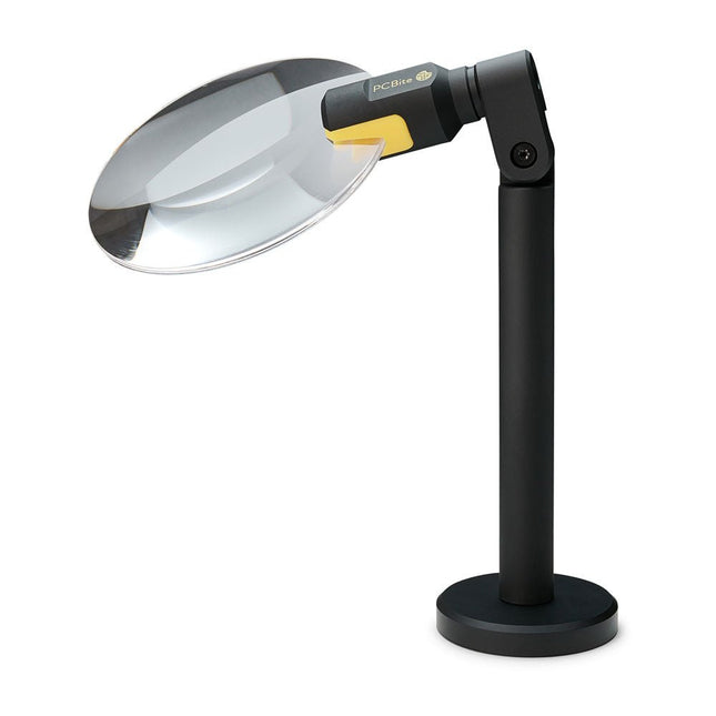
Sensepeek Sensepeek 4020 PCBite 3x Magnifier
The PCBite Magnifier (premium build quality made from CNC machined aluminum) enlarges your target and makes it easier to see during soldering, inspection and measurements. Especially useful when placing PCBite hands free probes on fine pitch SMD components during measurements. 3x magnification edgeless lens for increased visibility of the work surface and AR coating (anti-reflection) to reduce reflections from nearby light sources. Optimized design, magnification and focal point for use together with the PCBite PCB holders and baseplates included in all PCBite kits. Can also be used handheld but not standalone without a metal surface as base. At the bottom of the magnifier foot there is a strong magnet perfectly balanced in strength. A low friction bottom cap protects the magnet and the baseplate to make the magnifier easy to slide when repositioning or removing the magnifier from the baseplate. Friction based adjustment of lens tilt and rotate positions takes away the need for annoying and complicated set screws.
€ 71,39
-

OWON OWON XDM1241 True RMS Multimeter
The OWON XDM1241 is a fast, high-precision digital True RMS benchtop multimeter with a high-resolution 3.5-inch LCD and 50,000 counts. Its DC voltage accuracy is up to 0.05% and it can measure up to 65 values per second. Features 3.5' high-resolution LCD (480x320 pixels) 55000 counts, DC voltage accuracy up to 0.05% Up to 65 readings per second Dual line display supported Trend analysis accessible in chart mode AC True RMS measurements (bandwidth: 20 Hz – 1 kHz) SCPI support: Remote control the multimeter through PC software via USB port Data record function, you can record the measured data into internal memory, and then read and process the recorded data with your computer. Specifications Measurement Range Resolution Accuracy DC Voltage 50.000 mV 0.001 mV 0.1% +10 500.00 mV 0.01 mV 0.05% +5 5.0000 V 0.0001 V 0.05% +5 50.000 V 0.001 V 0.05% +5 500.00 V 0.01 V 0.1% +5 1000.0 V 0.1 V 0.1% +10 AC Voltage 500 mV~750 V 20 Hz~45 Hz 1% +30 45 Hz~65 Hz 0.5% +30 65 Hz~1 KHz 0.7% +30 DC Current 500 uA 0.01 uA 0.15% +20 5000 uA 0.1 uA 0.15% +10 50 mA 0.001 mA 0.15% +20 500 mA 0.01 mA 0.15% +10 5 A 0.0001 A 0.5% +10 10 A 0.001 A 0.5% +10 AC Current 500 uA~500 mA 20 Hz~1 KHz 0.5% +20 5 A-10 A 1.5% +20 Resistance 500 Ω 0.01 Ω 0.15% +10 5 KΩ 0.0001 KΩ 0.15% +5 50 KΩ 0.001 KΩ 0.15% +5 500 KΩ 0.01 KΩ 0.15% +5 5 MΩ 0.0001 MΩ 0.3% +5 50 MΩ 0.001 MΩ 1% +10 Frequency 10.000 Hz~60 MHz / ±(0.2% +10) Capacitance 50 nF~500 uF / 2.5% +10 5 mF~50 mF 5% +10 Diode 3.0000 V 0.0001 V / Continuity 1000 Ω 0.1 Ω Adjustable threshold Temperature K type, PT100 Max Display 55,000 counts Data-logging Function Logging Duration 15ms~9999.999s Logging Length 1,000 points Display 3.5' TFT LCD (480x320 pixels) Power supply Lithium battery via USB-C or 5 V DC input Dimensions 235 x 88 x 65 mm Weight approx. 0.5 kg Included 1x OWON XDM1241 Multimeter 2x Test leads 1x USB cable 1x USB to DC cord 1x Manual Downloads Programming Manual PC Software
€ 108,90
-
Elektor Digital Elektor Circuit Special 2024 PDF (EN)
Elektor GREEN and GOLD members can download their digital edition here. Not a member yet? Click here. Digital Load for High-Current TestingFrom Necessity to Innovation Vocal RemoverInstant Karaoke Circuit Audio A/B Selector With Gain ControlSwitches from Microphone to Line Inputs Better Charging for the LIR2032Be Kind to Your Coin Cells Touch Sensing Made SimpleA DIY Guide for Any Microcontroller Universal Infrared Remote SwitchA New Life for Old Remotes Microcontroller-Powered Moo BoxMaking Playful Sounds With a Microcontroller USB Battery Interface Powering Low-Draw Devices With Power BanksA “Stay Alive” Solution Small Class-A Audio Amplifier With Current OutputDrive Speakers with Current Instead of Voltage Pseudo-Balanced ModuleHigh CMRR with Unbalanced Audio Links Ni-MH Cells Automatic ChargerRefill All Your Battery Packs in One Go! Thyristor-Based Power Supply Protection Fingerprint Sensor SwitchA Useful Proof-of-Identity Device DC-DC 3-A Power ConverterUpgrade Your Fixed-Voltage Sources Remote Water Heater MonitorVoltage and Current Detection for AC Lines Attenuators for Audio Signals (1)Adjustable Via Jumpers Pimp My Car Battery Charger (Part 1)Don’t Throw It Away, Mod It! A Board for the Blue OnePCB for Alps Motorized Potentiometer with Feedback 50-Hz Reference from 60-Hz Mains VoltageHow to Use 50-Hz Electronics in 60-Hz Environments Digital IsolatorsRealizing Galvanic Isolation Easily Compact 12-W Hi-Fi Mono AmplifierSmall But Powerful LM386 Ramp Generator Three-Phase GeneratorWith Raspberry Pi Pico Door Opener for the Musically Talented Elektor Classic: Surf SynthesizerOcean Watersports Background Sound Generator (OWBSG) Pimp my Car Battery Charger (Part 2)Don’t Throw It Away, Mod It! Lamp Current MonitorWith a Raspberry Pi Pico Infrared Telegraphy Fnirsi SWM-10Repair Battery Packs With This Portable Intelligent Spot Welding Machine Stereo Audio Codec for the ESP32 and Co.No Need to Be Afraid of Audio Measurement Technology Tin Soldering TechniquesMake Them Well Right Away! Attenuators for Audio Signals (2)Switching Via Relays USB-C PowerDrawing Power from USB-C Power Adapters Three Circuits with Two and Three Counter ICs4017 ICs Working Together Active Components – The Diode A Timer For Ultra-Long DelaysSet It, and Forget It! Jack In and Jack OutA Useful Insert Option for Audio Circuits Power an ESP32 from a Single Li-ion Cell Hexadoku
€ 7,50
-
Elektor Digital C Programming for Embedded Microcontrollers (E-book)
Technology is constantly changing. New microcontrollers become available every year and old ones become redundant. The one thing that has stayed the same is the C programming language used to program these microcontrollers. If you would like to learn this standard language to program microcontrollers, then this book is for you! ARM microcontrollers are available from a large number of manufacturers. They are 32-bit microcontrollers and usually contain a decent amount of memory and a large number of on-chip peripherals. Although this book concentrates on ARM microcontrollers from Atmel, the C programming language applies equally to other manufacturer’s ARMs as well as other microcontrollers. Features of this book Use only free or open source software. Learn how to download, set up and use free C programming tools. Start learning the C language to write simple PC programs before tackling embedded programming - no need to buy an embedded system right away! Start learning to program from the very first chapter with simple programs and slowly build from there. No programming experience is necessary! Learn by doing - type and run the example programs and exercises. Sample programs and exercises can be downloaded from the Internet. A fun way to learn the C programming language. Ideal for electronic hobbyists, students and engineers wanting to learn the C programming language in an embedded environment on ARM microcontrollers.
€ 29,95
Members: € 26,96
-
Elektor Digital ESP8266 and MicroPython (E-book)
Recently, the development of a tiny chip called the ESP8266 has made it possible to interface any type of microcontroller to a Wi-Fi AP. The ESP8266 is a low-cost tiny Wi-Fi chip having fully built-in TCP/IP stack and a 32-bit microcontroller unit. This chip, produced by Shanghai based Chinese manufacturer Espressif System, is IEEE 802.11 b/g/n Wi-Fi compatible with on-chip program and data memory, and general purpose input-output ports. Several manufacturers have incorporated the ESP8266 chip in their hardware products (e.g. ESP-xx, NodeMCU etc) and offer these products as a means of connecting a microcontroller system such as the Android, PIC microcontroller or others to a Wi-Fi. The ESP8266 is a low-power chip and costs only a few Dollars. ESP8266 and MicroPython – Coding Cool Stuff is an introduction to the ESP8266 chip and describes the features of this chip and shows how various firmware and programming languages such as the MicroPython can be uploaded to the chip. The main aim of the book is to teach the readers how to use the MicroPython programming language on ESP8266 based hardware, especially on the NodeMCU. Several interesting and useful projects are given in the e-book (pdf) to show how to use the MicroPython in NodeMCU type ESP8266 hardware: Project “What shall I wear today?”: You will be developing a weather information system using a NodeMCU development board together with a Text-to-Speech processor module. Project “The Temperature and Humidity on the Cloud”: You will be developing a system that will get the ambient temperature and humidity using a sensor and then store this data on the cloud so that it can be accessed from anywhere. Project “Remote Web Based Control”: You will be developing a system that will remotely control two LEDs connected to a NodeMCU development board using an HTTP Web Server application.
€ 29,95
Members: € 26,96
-

Elektor Publishing SDR with HackRF One & HackRF Pro
Programming with GNU Radio HackRF is an open-source hardware platform developed by Great Scott Gadgets and serves as a versatile front end for software-defined radio (SDR). With HackRF One and its successor, HackRF Pro, users can develop their own SDR applications, build powerful receivers and transmitters, and tackle demanding RF measurement tasks. This book provides a practical introduction to the world of SDR. Step by step, the author shows how powerful SDR projects can be implemented with HackRF – from the fundamentals of RF technology to advanced applications using GNU Radio. In addition to working with SDR Sharp (SDR#), RadioConda, and GNU Radio, the book also covers the fundamentals of modern digital signal processing. Numerous experiments and easy-to-follow practical examples guide readers through topics such as AM, FM, and SSB reception, digital filters, shortwave radio, amateur radio, signal generators, and custom RF projects up to 6 GHz. Whether you are a maker, radio amateur, electronics enthusiast, or SDR beginner, this book provides solid knowledge, practical applications, and the motivation to creatively explore the possibilities of modern SDR technology.
€ 24,95
Members: € 22,46
-

OWON OWON OW18E True RMS Multimeter
Features 4 1/2 bit resolution (20000 Counts) Data Logger Multimeter Thermometer True RMS test supported BLE 4.0 wireless transmission, more stable,less power consumption Build-in offline record function Chart and Diagram mode helps to analyze the data tendency Flashlight function lightens the darkness Support NCV non-contact voltage sense Widely supported on Android, iOS, Windows Included OWON OW18E Multimeter Quick Guide Multimeter Lead K-type Thermocouple Bolt Driver App Download The Bluetooth function of this multimeter is compatible with Android-app version 1.5.8.0 or newer. Use the QR code in the box or go to http://files.owon.com.cn/bluetooth.
€ 59,95
-

OWON OWON HDS242 2-ch Oscilloscope (40 MHz) + Multimeter
The HDS242 is a portable 2-in-1 multifunctional tester, which can be used as a 2-ch oscilloscope and multimeter. It features a high-contrast 3.5-inch color display suitable for outdoor facility maintenance, rapid on-site measurement, automobile maintenance, power detection. etc. Features Oscilloscope + Multimeter 3.5-inch high-resolution, high-contrast color LCD display – suitable for outdoor use 18650 lithium battery – can work continuously for up to 6 hours USB-C interface – support power bank and PC connection Self-calibration function SCPI supported – facilitate secondary development Specifications Oscilloscope Bandwidth 40 MHz Channels 2-ch Oscilloscope Sample Rate 250 MSa/s Acquisition Model Normal, Peak detect Record Length 8K Display 3.5-inch LCD Waveform Refresh Rate 10,000 wfrms/s Input Coupling DC, AC, and Ground Input Impedance 1 MΩ ±2%, in parallel with 16pF ±10pF Probe Attenuation Factors 1X, 10X, 100X, 1000X, 10000X Max. Input Voltage 400 V (DC+AC, PK-PK, 1MΩ input impedance) (10:1 probe attenuation) Bandwidth Limit (typical) 20 MHz Horizontal Scale 5ns/div - 1000s/div, step by 1 - 2 - 52ns/div - 1000s/div, step by 1 - 2 - 55ns/div - 1000s/div, step by 1 - 2 - 52ns/div - 1000s/div, step by 1 - 2 - 5 Vertical Sensitivity 10mV/div - 10V/div Vertical Resolution 8 bits Trigger Type Edge Trigger Modes Auto, Normal, single Automatic Measurement Frequency, Period, Amplitude, Max, Min, Mean, PK-PK Cursor Measurement ΔV, ΔT, ΔT & ΔV between cursors Multimeter Max. Resolution 20,000 counts Testing Mode Voltage, Current, Resistance, Capacitance, Diode, and Continuity test Input Impedance 10 MΩ Max Input Voltage AC: 750 V | DC: 1000 V Max Input Current DC: 10 A | AC: 10 A Diode 0-2 V Other Connectivity USB Type-C Dimensions 198 x 96 x 38 mm (7.68 x 3.74 x 1.5') Weight 600 g (without batteries) Included 1x OWON HDS242 Oscilloscope 1x Soft Bag 1x Probe 1x Power Cord 1x Probe Adjust 1x USB Cable 1x Power Adapter 1x Pair of Multimeter Probe Leads (red one and black one) 1x Pair of Oscilloscope Probe Leads (BNC to Alligator Clip) 1x User Manual (English) Downloads User Manual SCPI Protocol Quick Guide PC Software
€ 112,87
-

Elektor Digital GSM/GPRS Projects (E-book)
Based on PIC microcontrollers and Arduino Every mobile phone includes a GSM/GPRS modem which enables the phone to communicate with the external world. With the help of the GSM modems, users can establish audio conversations and send and receive SMS text messages. In addition, the GPRS modem enables users to connect to the internet and to send and receive large files such as pictures and video over the internet. This book is aimed for the people who may want to learn how to use the GSM/GPRS modems in microcontroller based projects. Two types of popular microcontroller families are considered in the e-book: PIC microcontrollers, and the Arduino. The highly popular mid-performance PIC18F87J50 microcontroller is used in PIC based projects together with a GSM Click board. In addition, the SIM900 GSM/GPRS shield is used with the Arduino Uno projects. Both GSM and GPRS based projects are included in the e-book. The book will enable you to control equipment remotely by sending SMS messages from your mobile phone to the microcontroller, send the ambient temperature readings from the microcontroller to a mobile phone as SMS messages, use the GPRS commands to access the internet from a microcontroller, send temperature readings to the cloud using UDP and TCP protocols and so on. It is assumed that the reader has some basic working knowledge of the C language and the use of microcontrollers in simple projects. Although not necessary, knowledge of at least one member of the PIC microcontroller family and the Arduino Uno will be an advantage. It will also be useful if the user has some knowledge of basic electronics.
€ 24,95
Members: € 22,46
-

Elektor Digital Controller Area Network Projects with ARM and Arduino (E-book)
This book details the use of the ARM Cortex-M family of processors and the Arduino Uno in practical CAN bus based projects. Inside, it gives a detailed introduction to the architecture of the Cortex-M family whilst providing examples of popular hardware and software development kits. Using these kits helps to simplify the embedded design cycle considerably and makes it easier to develop, debug, and test a CAN bus based project. The architecture of the highly popular ARM Cortex-M processor STM32F407VGT6 is described at a high level by considering its various modules. In addition, the use of the mikroC Pro for ARM and Arduino Uno CAN bus library of functions are described in detail. This book is written for students, for practising engineers, for hobbyists, and for everyone else who may need to learn more about the CAN bus and its applications. The book assumes that the reader has some knowledge of basic electronics. Knowledge of the C programming language will be useful in later chapters of the book, and familiarity with at least one microcontroller will be an advantage, especially if the reader intends to develop microcontroller based projects using CAN bus. The book should be useful source of reference to anyone interested in finding an answer to one or more of the following questions: What bus systems are available for the automotive industry? What are the principles of the CAN bus? What types of frames (or data packets) are available in a CAN bus system? How can errors be detected in a CAN bus system and how reliable is a CAN bus system? What types of CAN bus controllers are there? What are the advantages of the ARM Cortex-M microcontrollers? How can one create a CAN bus project using an ARM microcontroller? How can one create a CAN bus project using an Arduino microcontroller? How can one monitor data on the CAN bus?
€ 32,95
Members: € 29,66
-

Elektor Digital Controller Area Network Projects (E-book)
The Controller Area Network (CAN) was originally developed to be used as a vehicle data bus system in passenger cars. Today, CAN controllers are available from over 20 manufacturers, and CAN is finding applications in other fields, such as medical, aerospace, process control, automation, and so on. This book is written for students, for practising engineers, for hobbyists, and for everyone else who may be interested to learn more about the CAN bus and its applications. The aim of this book is to teach you the basic principles of CAN networks and in addition the development of microcontroller based projects using the CAN bus. In summary, this book enables the reader to: Learn the theory of the CAN bus used in automotive industry Learn the principles, operation, and programming of microcontrollers Design complete microcontroller based projects using the C language Develop complete real CAN bus projects using microcontrollers Learn the principles of OBD systems used to debug vehicle electronics You will learn how to design microcontroller based CAN bus nodes, build a CAN bus, develop high-level programs, and then exchange data in real-time over the bus. You will also learn how to build microcontroller hardware and interface it to LEDs, LCDs, and A/D converters. The book assumes that the reader has some knowledge on basic electronics. Knowledge of the C programming language will be useful in later chapters of the book, and familiarity with at least one member of the PIC series of microcontrollers will be an advantage, especially if the reader intends to develop microcontroller based projects using the CAN bus.
€ 29,95
Members: € 26,96
-
Würth Trilogy of Connectors, 3rd Edition (E-book)
Contents Basic principles A connector is an electromechanical system that provides a separable connection between two subsystems of an electronic device without an unacceptable effect on the performance of the device. It will be shown that there are a lot of complex parameters to handle properly to make this statement true. Design / Selection / Assembly This chapter provides an overview of design and material requirements for contact finishes, contact springs and connector housings as well as the major degradation mechanisms for these connector components. To complete this chapter, material selection criteria for each will also be reviewed. Additionally the Level of Interconnection (LOI) was integrated into this chapter as it addresses, where the connector is used within an electronic system and therefore influences the requirements and durability of the connector depending on its use. Applications This chapter is heading to the practical work and shows how customers use connectors in their applications to offer some possibilities and to ease your daily work. Additionally it contains some special topics like tin-whisker or impedance of ZIF cable to offer you extended background knowledge.
€ 26,99
Members: € 24,29


