Programmers & Debuggers
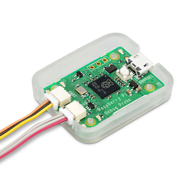
Raspberry Pi Foundation Raspberry Pi Debug Probe
The Raspberry Pi Debug Probe is an all-in-one USB-to-debug kit that provides all the necessary hardware and cables for easy, solderless, plug-and-play debugging. It features both a processor serial debug interface (by default the ARM Serial Wire Debug interface, but other interfaces can be supported) and an industry-standard UART interface. Both interfaces use the Raspberry Pi 3-pin debug connector. It is designed to make it easy to debug and program Raspberry Pi Pico and RP2040 with a range of host platforms including Windows, Mac, and typical Linux computers. While designed for use with Raspberry Pi products, the Debug Probe provides standard UART and CMSIS-DAP interfaces over USB, so it can also be used with other processors, or even just as a USB-to-UART cable. It works with OpenOCD and other tools that support CMSIS-DAP. The Debug Probe is based on Raspberry Pi Pico hardware and runs the open source Raspberry Pi Picoprobe software. The firmware is updated in the same way as Raspberry Pi Pico firmware, so it is easy to keep the unit up to date with the latest firmware, or to use custom firmware. Features USB to ARM Serial Wire Debug (SWD) port USB to UART bridge Compatible with the CMSIS-DAP standard Works with OpenOCD and other tools supporting CMSIS-DAP Open source, easily upgradeable firmware Specifications Dimensions: 22 x 32 mm Nominal I/O voltage: 3.3 V Operating temperature: -20°C to +70°C Included 1x Raspberry Pi Debug Probe 1x Plastic case 1x USB cable 3x Debug cables 3-pin JST connector to 3-pin JST connector cable 3-pin JST connector to 0.1-inch header (female) 3-pin JST connector to 0.1-inch header (male) Downloads Datasheet 3-pin Debug Connector Schematics Diagram
€ 14,95
Members identical
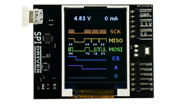
Excamera Labs SPIDriver
SPIDriver shows you what’s happening on the SPI bus in real time, so no more guessing about the bus state. Its purpose is to make understanding the functioning of SPI hardware more intuitive. It's useful if you're into debugging hardware or simply introduce a class to SPI for the first time.You can directly control LEDs and LCD displays just by having SPIDriver and you won't have to deal with microcontrollers. It's also a useful tool for examining, backing up and cloning an SPI flash as well as reading and writing SPI flash in circuit.SPIDriver is also applicable if you want to drive, test and evaluate different displays.With the help of current and voltage monitoring you'll be able to detect electrical problems at early stages. Thanks to the included color coded wires you can hook SPIDriver up without much effort; no pinout diagram required. It includes 3.3 V and 5 V supplies for your device, plus a high-side current meter.SPIDriver comes with software to control it from: a GUI the command-line C and C++ using a single source file Python 2 and 3, using a module Technical features Live display shows you exactly what it’s doing all the time Sustained SPI transfers at 500 Kbps USB line voltage monitor to detect supply problems, to 0.01 V Target device high-side current measurement, to 5 mA Two auxiliary output signals, A and B Two dedicated power outlines: of 3.3 V and 5 V All signals color coded to match jumper colors All signals are 3.3 V, and are 5 V tolerant Uses an FTDI USB serial adapter, and Silicon Labs automotive-grade EFM8 controller Also reports uptime, temperature, and running CRC of all traffic All sensors and signals controlled using a simple serial protocol GUI, command-line, C/C++, and Python 2/3 host software provided for Windows, Mac, and Linux Details Maximum power out current: up to 470 mA Signal current: up to 10 mA Device current: up to 25 mA Dimensions: 61 mm x 49 mm x 6 mm Interface: USB 2.0, micro USB connector Contents (SPIDriver Core) 1x SPIDriver 1x Set of hookup jumpers
€ 49,95
Members € 44,96
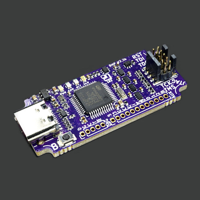
1 Bit Squared Black Magic Probe V2.3 - JTAG/SWD ARM Microcontroller Debugger
Black Magic Probe V2.3 is a JTAG and SWD Adapter with a built-in GDB server used for programming and debugging ARM Cortex MCUs. Its the best friend of any ARM microcontroller developer. All proceeds from BMP hardware sales go directly into the continued development, maintenance and support of the Open-Source Black Magic Debug project. Black Magic Probe gets rid of intermediate programs like OpenOCD or STLink server. This makes the operation faster and more reliable. You just open your GNU Debugger (GDB) and select the virtual com port offered by BMP23 as your extended remote target. For a full description and how-to visit the project website. Features Wide target IO voltage range support, 1.7 V up to 5 V, thanks to VREF referenced level shifters Power switch allowing supply of 3.3 V to the target through the VREF pin Standard ARM-Cortex 0.05' pitch 10pin debug connector Aux UART capable of up to 2 MBaud Small size (4 x 2 x 1 cm) (1.3 x 0.6 x 0.45'), saving space in your field kit and allowing the use of the debugger in very tight spaces and enclosures Jumpers allowing the connection of the UART TX/RX pins to the JTAG/SWD connector resulting in a 'Unified debug' connector TraceSWO UART, decoding hardware support 16 MByte on board flash AUX connector for accessories Mechanical layout allowing easier use of enclosures and mounting into bigger systems. For example: automated pogopin test equipment, automated Hardware In The Loop (HITL) Continous Integration (CI) systems Improved layout, allowing further improvement of the Black Magic Debug firmware reliability and speed using hardware protocol acceleration Included 1x Black Magic Probe Mini V2.3 (BMP23) 1x JTAG Ribbon Cable 1x 0.1' Header Serial Cable 1x 10-pin ARM Cortexto7-pin Adapter 1x UART 0.1' Cable Dimensions 70 x 17 mm (1.3 x 0.6 in) 3.6 g (0.128 oz)
€ 114,95
Members € 103,46
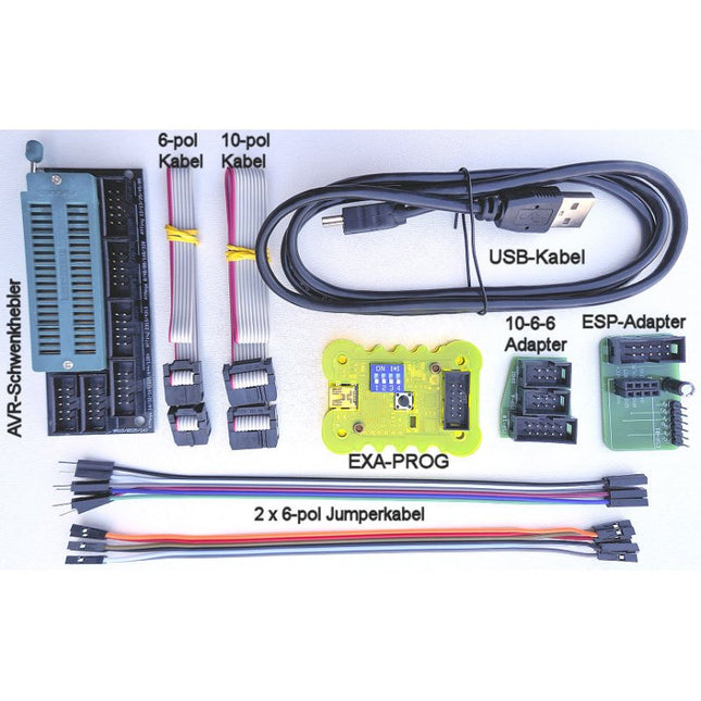
Diamex Diamex EXA-Prog Package
EXA-Prog in housing EXA-Prog represents the new generation of ISP programmers, which are not limited to one specific microcontroller type, but support several different controller architectures and programming interfaces. Laser-cut plexiglass housing. Two built-in status LEDs signal the current state of the programmer. Features Function selection via DIP switch Signal level switchable, 3.3 V, 5 V Integrated high voltage generator for UPDI programming Automatic bit-rate adjustment in AVR-ISP mode Clock generator for AVR controller with fuse oscillator Button to reset the connected microcontroller 10-pin standard ISP connector Optional accessories: 10-pin to 6-pin adapter, ESP01 adapter Mini-USB connector for power supply and connection to PC Firmware can be updated via USB Windows PC tool for testing the signal levels at the programming port. Current consumption without microcontroller connected: approx. 30 mA Signal level at programming connector: 5 V (USB voltage) or 3.3 V Power supply for the external circuit: max. 300 mA (3.3 V), max. 500 mA (5 V) UPDI high voltage: approx. 12.3 V Weight: approx. 25 g Adapter 10-pin to 6-pin IS P and 6-pin UPDI The optimal solution for in-system programming (ISP) of AVR controllers. There are two different standards for the AVR-ISP interface, 6-pin and 10-pin. With this adapter kit, you can exchange the programming lines between both standards. For programming AVR-UPDI a 6-pin connector is also needed. This adapter supports 10-pin to 6-pin for AVR-ISP programming and 10-pin to 6-pin for AVR-UPDI programming. ESP adapter No buttons or switches are needed to activate the ESP bootloader. When ESPTOOL is used, the bootloader is automatically activated and the firmware is started after programming is complete. If another program is used that does not take over this control itself, the bootloader of the ESP can also be activated by a long press on the RESET button of the EXA-PROG and the firmware can be started by a short press after programming. AVR swivel lever High-quality module with swivel lever zero force socket for almost all AVR controllers in DIL package. No own board is required. DIL controllers are easy and fast to program. Can also be used for series production. The 10-pin ISP standard connector from Atmel is used. Additionally, pin 3 is designed as a clock connector if the controller is set to an external clock. 5x 10-pin ISP well connectors for AVR controller in DIL package Compatible with all signal levels Pin 3 for the clock generator High quality swing lever socket (zero force socket) for variable 4-18 mm pin spacing Included EXA-Prog in housing Adapter 10-pin to 6-pin ISP and 6-pin UPDI ESP adapter AVR swivel lever Mini-USB cable 10-pin connection cable 6-pin connection cable 6-pin jumper cable, male-female 6-pin jumper cable, female-female
€ 74,95€ 64,95
Members identical
Microchip Microchip MPLAB PICkit 5 in-circuit debugger/programmer
The MPLAB PICkit 5 in-circuit debugger/programmer enables quick prototyping and portable, production-ready programming for all Microchip devices, including PIC microcontrollers (MCUs) and dsPIC Digital Signal Controllers (DSCs), AVR and SAM devices and Arm Cortex-based microprocessors (MPUs). It works alongside the MPLAB X Integrated Development Environment (IDE) to provide a powerful and easy-to-use Graphical User Interface (GUI) for debugging and programming. Alternatively, the MPLAB PICkit 5 in-circuit debugger/programmer can be used stand-alone with the MPLAB Programmer-to-Go (PTG) mobile app, allowing you to connect to the tool from your smartphone via Bluetooth. With stand-alone programming features accessible from your smartphone, the MPLAB PICkit 5 in-circuit debugger/programmer is a versatile programming companion that lets you prototype and debug your solution and then unplug and bring the device with you to deploy that solution out in the field. Features Improved Programmer-to-Go (PTG) support with the MPLAB PTG mobile app Connect wirelessly from your smartphone via Bluetooth Select from multiple saved program images on the SD card Start programming from the app or by pressing on the logo Supply 150 mA to the target Option to be self-powered from the target (2.7 V to 5 V) Simplify your workspace USB-C connector and cable No external power needed when the device is powered by high-speed USB 2.0 Use the eight-pin single in-line header Supports JTAG, SWD, UART VCP Adapter board allows use of standard connectors for JTAG, SWD, ICSP, and AVR Protocols Reduce Costs Features and performance at a fraction of the cost of comparable debuggers/programmers Included 1x MPLAB PICkit 5 In-Circuit Debugger/Programmer 1x USB-A to USB-C cable 2x MPLAB PICkit 5 In-Circuit Debugger/Programmer (stickers) Downloads User guide MPLAB X IDE
€ 164,95
Members € 148,46
Microchip Microchip MPLAB ICD 5 in-circuit debugger/programmer
The MPLAB ICD 5 In-Circuit Debugger/Programmer offers advanced connectivity and power options for developers of designs based on PIC, AVR and SAM devices and dsPIC Digital Signal Controllers (DSCs). It debugs and programs with the powerful and easy-to-use graphical user interface of MPLAB X Integrated Development Environment (IDE). This next-generation tool offers a variety of capabilities and features that you would normally find in more expensive products to speed up your development and reduce your debug time. With its support for Fast Ethernet connectivity and Power over Ethernet Plus (PoE+), the MPLAB ICD 5 Debugger/Programmer offers flexibility and the convenience of remote development while isolating your application from environmental conditions. Whether you're an experienced developer or just starting out, the MPLAB ICD 5 In-Circuit Debugger/Programmer will accelerate your development process and help you take your designs to the next level. Features USB-C interface makes it easy to connect to a PC High-Speed USB 2.0 host PC interface supports speeds up to 480 Mbps for fast data transfer rates PoE+ (IEEE 802.3at) offers a convenient and flexible option to power up the debugger/programmer and deliver power to the target Fast Ethernet connectivity supports speeds up to 100 Mbps Wired/DHCP/APIAP IP addressing Static IP addressing Connects to more targets using an RJ11 or RJ45 modular cable Includes adapter board that supports JTAG, SWD, ICSP and AVR MCU protocols Professional-grade safety features and support for devices ranging from 1.2 V to 5.5 V Safely powers the target at up to 1 A using the PoE power supply or a PC with a USB-C connector Receives feedback from debugger when an external power supply is needed for the target CE and RoHS compliant, conforms to industry standards Advanced trace capabilities Support for instrumented trace via the Arm Serial Wire Debug (SWD) interface Power monitoring Allows you to optimize your design's power consumption Captures power data, such as current and voltage values Works with MPLAB Data Visualizer, which graphically analyzes power data Data gateway interfaces UART over Windows Virtual COM Port (VCP) Power Continuous Integration/Continuous Delivery (CI/CD) Support Can be implemented over Ethernet using hardware in the loop Works with CI/CD wizard available with MPLAB X IDE v6.10 and later to set up system using Jenkins and Docker Powerful debugging High-powered debugging with MPLAB X IDE Multiple breakpoints, stopwatch and source code file debugging Selectable pull-up/pull-down option to the target interface in MPLAB X IDE’s editor for quick program modification and debugging High-speed programming Quick firmware reloading for fast debugging and in-circuit reprogramming Debugging speed can be adjusted for optimized programming Included MPLAB ICD 5 In-Circuit Debugger and Programmer USB-C cable Adapter kit Downloads User guide Datasheet
€ 649,00
Members € 584,10


