Physical Products
-
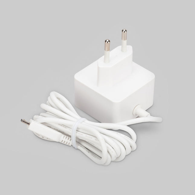
Raspberry Pi Foundation Official Micro-USB Power Supply for Raspberry Pi
Official Micro-USB Power Supply for Raspberry Pi (12.5 W) Input: 100-240 VAC Output: 5.1 V / 2.5 A power supply Connector: micro USB Length: 1.5 m
-

The Elektor RF & Communications Collection (USB Stick)
This USB stick holds a selection of more than 350 articles on RF, Radio and Communication published in Elektor Magazine. The content consists of both background articles and projects with the following topics: Basic radio-related circuits as well as more complex circuits like filters, oscillators, and amplifiers. Design, construction, and theory of antennas for transmitting and receiving radio signals efficiently. Design and analysis of RF circuits including filters, mixers, PLLs, and frequency synthesizers. Tools and techniques for predicting radio wave propagation paths and measuring RF signal strength. Techniques for processing digital signals in RF systems, including modulation and demodulation methods. Projects on radio receivers, AM, FM, SSB, CW, DRM, DAB, DAB+, Software Defined Radio, and more. Projects on Wi-Fi, Bluetooth, LoRaWAN, and more. You can use the article search function to locate specific content in the full text. The results are always shown as preformatted PDF documents. You can use Adobe Reader to browse articles, and you can use Adobe Reader’s integrated search functions to find instances of individual words and expressions.
€ 49,95€ 34,95
Best Price
-
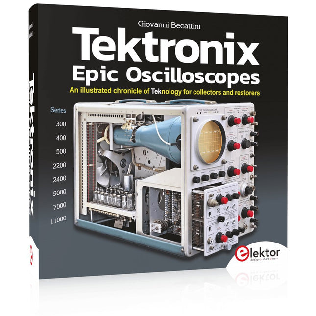
Elektor Publishing Tektronix Epic Oscilloscopes
An illustrated chronicle of Teknology for collectors and restorers Oscilloscopes have made a major contribution to the advancement of human knowledge, not only in electronics, but in all sciences, whenever a physical quantity can be converted into a timerelated electrical signal. This book traces the history of a crucial instrument through many Tektronix products. This is the company that invented and patented most of the functions found in all oscilloscopes today. Tek is and will always be synonymous with the oscilloscope. In nearly 600 pages, with hundreds of gorgeous photos, diagrams, anecdotes, and technical data, you'll travel through the history of Tektronix in a superb collector's edition with a technical point of view. The author is not afraid to get his hands dirty restoring his own Tek equipment. The journey starts in the early 1950s. It ends in the '90s, after exploring the ins and outs of the most interesting models in the 300, 400, 500, 5000, 7000, and 11000 series, from tubes to advanced hybrid technologies. Downloads NEW: Free Supplement (136 pages, 401 MB)
€ 79,95
Members: € 71,96
-
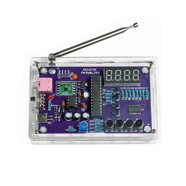
Generic FM Radio Kit
This DIY kit (HU-017A) is a wireless FM radio receiver with a 4-digit 7-segment display. It operates within the global FM receiving frequency band of 87.0-108.0 MHz, making it suitable for use in any country or region. The kit offers two power supply modes, allowing you to use it both at home and outdoors. This DIY electronic product will help you understand circuits and improve your soldering skills. Features 87.0-108.0 MHz FM Radio: Built-in RDA5807 FM data processor with a standard FM receiving frequency band. The FM frequency can be adjusted using the F+ and F- buttons. Adjustable Volume: Two volume adjustment methods – button and potentiometer. There are 15 volume levels. Active & Passive Audio Output: The kit has a built-in 0.5 W power amplifier to drive 8 Ω speakers directly. It also outputs audio signals to headsets or loudspeakers with AUX interfaces, allowing personal listening and sharing of FM audio. Configured with a 25 cm dedicated FM antenna and a (red) 4-digit 7-segment display for real-time display of FM radio frequency. The transparent acrylic shell protects the internal circuit board. It supports dual power supply methods – 5 V USB and 2x 1.5 V (AA) batteries. DIY Hand Soldering: The kit comes with various components that need to be installed manually. It helps exercise and improve soldering skills, making it suitable for electronics hobbyists, beginners, and educational purposes. Specifications Operating voltage DC 3 V/5 V Output impedance 8 Ω Output power 0.5 W Output channel Mono Receiver frequency 87.0 MHz~108.0 MHz Frequency accuracy 0.1 MHz Operating temperature −40°C to +85°C Operating humidity 5% to 95% RH Dimensions 107 x 70 x 23 mm IMPORTANT: Remove the batteries when powering the radio over to USB. Included 1x PCB 1x RDA5807M FM Receiver 1x STC15W404AS MCU 1x IC Socket 1x 74HC595D Register 1x TDA2822M Amplifier 1x IC Socket 1x AMS1117-3.3 V Voltage Converter 18x Metal Film Resistor 1x Potentiometer 4x Ceramic Capacitor 5x Electrolytic Capacitor 4x S8550 Transistor 1x Red LED 1x 4-digit 7-segment Display 1x Toggle Switch 1x SMD Micro USB Socket 1x Radio Antenna 1x AUX Audio Socket 4x Black Button 4x Button Cap 1x 0.5 W/8 Ω Speaker 1x Red/Black Wire 2x Double-sided adhesive 1x AA Battery Box 1x USB cable 6x Acrylic Board 4x Nylon Column Screw 4x M3 Screw 4x M3 Nut 4x M2x22 mm Screw 1x M2x6 mm Screw 5x M2 Nut
-

Elektor Publishing High-End Tube Amplifier Design
A Toolbox for Audio Lovers and Engineers Without any ambition to reach scientific levels, this book aims to be a toolbox for both audio lovers and high-end equipment designers. The elementary theory presented is the bare minimum for readers to grasp the operation and practical use of electrical, electromagnetic, physics, and electronic operations available in the designers’ toolbox. Each tool is explained in a minimum of words and theory without needless coverage of underlying equations or figures. The book chapters guide you through the process of designing quality amplifiers with vacuum tubes, from the very beginning, considering both technical and subjective requirements – in theory and practice. The book is a compilation of the author’s notes used in his professional and educational career but was nevertheless primarily written as a result of true love for the audiophile hobby.
€ 69,95
Members: € 62,96
-
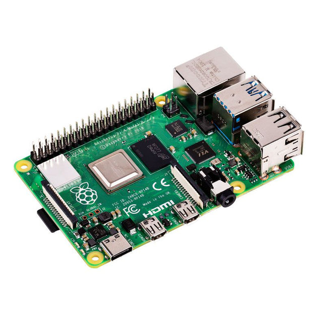
Raspberry Pi Foundation Raspberry Pi 4 B (1 GB RAM)
The Raspberry Pi 4 B is 3x faster than its 3 B+ predecessor and offers 4x faster multimedia performance (comparable to the desktop performance of an entry-level x86-based PC). Features High-performance 64-bit quad-core processor Dual-display support at resolutions up to 4K via a pair of micro-HDMI ports Hardware video decode at up to 4Kp60 Up to 8 GB of RAM Dual-band 2.4/5 GHz wireless LAN Bluetooth 5.0 Gigabit Ethernet USB 3.0 PoE capability (via a separate PoE HAT add-on) Specifications SoC Broadcom BCM2711 CPU 64-bit ARM Cortex-A72 (4x 1.5 GHz) GPU Broadcom VideoCore VI RAM Up to 8 GB LPDDR4 Wireless LAN 2.4 GHz and 5 GHz IEEE 802.11b/g/n/ac wireless LAN Bluetooth Bluetooth 5.0, BLE Ethernet Gigabit Ethernet USB 2x USB-A 3.02x USB-A 2.0 GPIO Standard 40-pin GPIO header (fully backwards-compatible with previous boards) Video 2x micro-HDMI ports (up to 4Kp60 supported)2-lane MIPI DSI port (display)2-lane MIPI CSI port (camera) Audio 4-pole stereo audio and composite video port Multimedia H.265 (4Kp60 decode)H.264 (1080p60 decode, 1080p30 encode)OpenGL ES, 3.0 graphics SD card microSD (for operating system and storage) Power 5 V | 3 A (via USB-C)5 V | 3 A (via GPIO)Power over Ethernet (PoE) enabled – (requires separate PoE HAT) Raspberry Pi 4 B 2 GB RAM 4 GB RAM 8 GB RAM
-
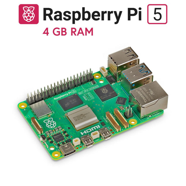
Raspberry Pi Foundation Raspberry Pi 5 (4 GB RAM)
The Raspberry Pi 5 delivers more performance than ever before. Thanks to the faster CPU, GPU and RAM, Raspberry Pi 5 is up to 3x faster than its already fast predecessor. In addition to the speed boost, the Raspberry Pi 5 (which features the new Raspberry Pi RP1 silicon for advanced I/O capabilities) also offers the following features for the first time ever: RTC, an on/off button and a PCIe interface. Features 64-bit quad-core ARM Cortex-A76 processor (2.4 GHz) VideoCore VII GPU (800 MHz) 4 GB of LPDDR4X RAM (4267 MHz) Raspberry Pi silicon RP1 I/O controller chip Real-time clock On/off button PCIe 2.0 UART connector Fan connector Specifications SoC Broadcom BCM2712 CPU ARM Cortex-A76 (ARM v8) 64-bit Clock speed 4x 2.4 GHz GPU VideoCore VII (800 MHz) RAM 4 GB LPDDR4X (4267 MHz) WiFi IEEE 802.11b/g/n/ac (2.4 GHz/5 GHz) Bluetooth Bluetooth 5.0, BLE Ethernet Gigabit Ethernet (with PoE+ support) USB 2x USB-A 3.0 (5 GBit/s)2x USB-A 2.0 PCI Express 1x PCIe 2.0 GPIO Standard 40-pin GPIO header Video 2x micro-HDMI ports (4K60)2x 4-lane MIPI (DSI/CSI) Multimedia H.265 (4K60 decode)OpenGL ES 3.1, Vulkan 1.2 SD card microSD Power 5 V/5 A (via USB-C)Power over Ethernet (PoE+) Raspberry Pi 4 vs Raspberry Pi 5 Raspberry Pi 4 Raspberry Pi 5 SoC Broadcom BCM2711 Broadcom BCM2712 CPU ARM Cortex-A72 (ARM v8) 64-bit ARM Cortex-A76 (ARM v8) 64-bit Clock speed 4x 1.5 GHz 4x 2.4 GHz L2 cache 1 MByte shared 4x 512 KByte L3 cache N/A 2 MByte shared GPU VideoCore VI (500 MHz) VideoCore VII (800 MHz) RAM 4 GB LPDDR4 (3200 MHz) 4 GB LPDDR4X (4267 MHz) WiFi IEEE 802.11b/g/n/ac (2.4 GHz/5 GHz) IEEE 802.11b/g/n/ac (2.4 GHz/5 GHz) Bluetooth Bluetooth 5.0, BLE Bluetooth 5.0, BLE Ethernet Gigabit Ethernet (with PoE support) Gigabit Ethernet (with PoE+ support) USB 2x USB-A 3.02x USB-A 2.0 2x USB-A 3.0 (5 GBit/s)2x USB-A 2.0 I/O controller chip N/A Raspberry Pi Silicon RP1 PCI Express N/A 1x PCIe 2.0 Real Time Clock (RTC) N/A RTC and RTC battery connector On/off button N/A Onboard power button Cooling N/A Fan connector GPIO Standard 40-pin GPIO header Standard 40-pin GPIO header UART via GPIO 1x UART connector SD card microSD slot (DDR50) microSD slot (SDR104) Video 2x micro-HDMI ports (4K60)1x 2-lane MIPI DSI port (display)1x 2-lane MIPI CSI port (camera) 2x micro-HDMI ports (4K60)2x 4-lane MIPI (DSI/CSI) Audio 4-pole 3.5 mm audio jack (stereo audio and composite video) N/A Multimedia H.265 (4K60 decode)H.264 (1080p60 decode, 1080p30 encode)OpenGL ES, 3.0 graphics H.265 (4K60 decode)OpenGL ES 3.1, Vulkan 1.2 Power 5 V/3 A (15 W)Power over Ethernet (PoE) 5 V/5 A (25 W), USB PDPower over Ethernet (PoE+) Raspberry Pi 5 2 GB RAM 8 GB RAM 16 GB RAM Downloads Datasheet Unboxing the Raspberry Pi 5 First Insights
-
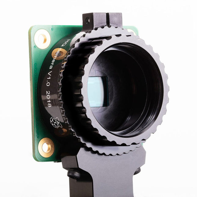
Raspberry Pi Foundation Raspberry Pi High Quality Camera Module
The Raspberry Pi High Quality Camera offers higher resolution (12 megapixels, compared to 8 megapixels), and sensitivity (approximately 50% greater area per pixel for improved low-light performance) than the existing Camera Module v2, and is designed to work with interchangeable lenses in both C and CS Mount form factors. Other lens form factors can be accommodated using third-party lens adapters. Specifications Sensor Sony IMX477R stacked, back-illuminated sensor12.3 megapixels7.9 mm sensor diagonal1.55 x 1.55 μm pixel size Output RAW12/10/8, COMP8 Back focus Adjustable (12.5–22.4 mm) Lens standards CS MountC Mount (C/CS adapter included) IR cut filter Integrated Ribbon cable length 200 mm Tripod mount 1/4”-20 Included 1x Circuit board carrying a Sony IMX477 sensor 1x FPC cable for connection to a Raspberry Pi 1x Milled aluminium lens mount with integrated tripod mount and focus adjustment ring 1x C/CS Mount adapter Required C/CS Mount Lens
-
Elektor Publishing FreeRTOS for ESP32-Arduino
Practical Multitasking Fundamentals Programming embedded systems is difficult because of resource constraints and limited debugging facilities. Why develop your own Real-Time Operating System (RTOS) as well as your application when the proven FreeRTOS software is freely available? Why not start with a validated foundation? Every software developer knows that you must divide a difficult problem into smaller ones to conquer it. Using separate preemptive tasks and FreeRTOS communication mechanisms, a clean separation of functions is achieved within the entire application. This results in safe and maintainable designs. Practicing engineers and students alike can use this book and the ESP32 Arduino environment to wade into FreeRTOS concepts at a comfortable pace. The well-organized text enables you to master each concept before starting the next chapter. Practical breadboard experiments and schematics are included to bring the lessons home. Experience is the best teacher. Each chapter includes exercises to test your knowledge. The coverage of the FreeRTOS Application Programming Interface (API) is complete for the ESP32 Arduino environment. You can apply what you learn to other FreeRTOS environments, including Espressif’s ESP-IDF. The source code is available from GitHub. All of these resources put you in the driver’s seat when it is time to develop your next uber-cool ESP32 project. What you will learn: How preemptive scheduling works within FreeRTOS The Arduino startup “loopTask” Message queues FreeRTOS timers and the IDLE task The semaphore, mutex, and their differences The mailbox and its application Real-time task priorities and its effect Interrupt interaction and use with FreeRTOS Queue sets Notifying tasks with events Event groups Critical sections Task local storage The gatekeeper task
€ 44,95
Members: € 40,46
-

FNIRSI FNIRSI FNB58 USB Tester (with Bluetooth)
The FNIRSI FNB58 USB tester (with Bluetooth) is a comprehensive and very accurate USB voltage and current meter. It features a 2.0-inch full-color HD TFT display, built-in USB-A, micro USB and USB-C interface. With this device you can measure the power supply or power consumption of products or the charging power of cell phones and power supplies. You can also determine the fast charging protocol of chargers. Features USB-A and USB-C interface 2.0" HD display Data at a glance Wide compatibility Ultra-precise data detection Play with fast charging technology Automatic protocol detection (PD2.0, 3.0, 3.1, PPS, QC2.0, 3.0, FCP, SCP, AFC, PE, DASH VOOC, SuperVOOC and more) Simple user interface, easy to operate 4 function curve displays (real-time voltage and current curve, offline curve recording, D+/D- voltage curve, high-speed power supply ripple measurement) Cable detection 10 groups of energy recording battery capacity calculation PC connectivity for data logging and firmware updates Bluetooth app for Android devices Specifications Voltage range 4-28 V Current range 0-7 A Power range 0-120 W Load equivalent internal resistance 0-9999.9 Ω D+/D- voltage 0-3.3 V Capacity 0-9999.99 Ah Power consumption 0-9999.99 Wh Cable resistance 0-9999.9 Ω Interfaces micro USB, USB-A, USB-C Dimensions 42 x 13 x 82 mm Downloads Manual Firmware V0.68
€ 49,95
-
Elektor Publishing Node-RED and Raspberry Pi Pico W
From basics to flows for sensors, automation, motors, MQTT, and cloud services This book is a learning guide and a reference. Use it to learn Node-RED, Raspberry Pi Pico W, and MicroPython, and add these state-of-the-art tools to your technology toolkit. It will introduce you to virtual machines, Docker, and MySQL in support of IoT projects based on Node-RED and the Raspberry Pi Pico W. This book combines several elements into a platform that powers the development of modern Internet of Things applications. These elements are a flow-based server, a WiFi-enabled microcontroller, a high-level programming language, and a deployment technology. Combining these elements gives you the tools you need to create automation systems at any scale. From home automation to industrial automation, this book will help you get started. Node-RED is an open-source flow-based development tool that makes it easy to wire together devices, APIs, and online services. Drag and drop nodes to create a flowchart that turns on your lights at sunset or sends you an email when a sensor detects movement. Raspberry Pi Pico W is a version of the Raspberry Pi Pico with added 802.11n Wi-Fi capability. It is an ideal device for physical computing tasks and an excellent match to the Node-RED. Quick book facts Project-based learning approach. Assumes no prior knowledge of flow-based programming tools. Learn to use essential infrastructure tools in your projects, such as virtual machines, Docker, MySQL and useful web APIs such as Google Sheets and OpenWeatherMap. Dozens of mini-projects supported by photographs, wiring schematics, and source code. Get these from the book GitHub repository. Step-by-step instructions on everything. All experiments are based on the Raspberry Pi Pico W. A Wi-Fi network is required for all projects. Hardware (including the Raspberry Pi Pico W) is available as a kit. Downloads GitHub
€ 49,95
Members: € 44,96
-

Elektor Bundles Universal Maker Sensor Bundle
Over 180 Projects with Raspberry Pi, Pico W, Arduino, and ESP32 This bundle contains the Universal Maker Sensor Kit, which consists of many sensors, actuators, displays, and motors. It’s perfect for environmental monitoring, smart home projects, robotics, and game controllers. The new Elektor book describes the design of many projects using the kit together with the popular Raspberry Pi, Raspberry Pi Pico W, Arduino Uno, and the ESP32 family of development boards. You can choose any of these development boards for your projects and either use the provided programs as they are, or modify these programs to suit your applications. This bundle contains: Book: Universal Maker Sensor Kit (normal price: €45) Universal Maker Sensor Kit (for Raspberry Pi, Pico W, Arduino, ESP32) (normal price: €70) Raspberry Pi Pico 2 W (normal price: €8) Book: Universal Maker Sensor Kit Learn to use more than 35 Sensors and Actuators with C++, Python, and MicroPython This book contains over 180 projects for all four major development boards (Arduino, Raspberry Pi, Pico W, and ESP32). Depending on the development board, projects are available in the C, Python, or MicroPython programming languages. The project titles, brief descriptions, wiring diagrams, and full program listings together with their detailed descriptions are given in the guide. Universal Maker Sensor Kit (for Raspberry Pi, Pico W, Arduino, ESP32) Discover endless creativity with the Universal Maker Sensor Kit, designed for use with Raspberry Pi, Pico W, Arduino, and ESP32. This versatile kit offers compatibility across popular development platforms, including Arduino Uno R4 Minima/WiFi, Uno R3, Mega 2560, Raspberry Pi 5, 4, 3B+, 3B, Zero, Pico W, and ESP32. Featuring over 35 sensors, actuators, and displays, it's perfect for projects ranging from environmental monitoring and smart home automation to robotics and interactive gaming. Step-by-step tutorials in C/C++, Python, and MicroPython guide beginners and experienced makers alike through 169 exciting projects. Features Wide Compatibility: Fully supports Arduino (Uno R3, Uno R4 Minima/WiFi, Mega 2560), Raspberry Pi (5, 4, 3B+, 3B, Zero, Pico W), and ESP32, enabling extensive flexibility across numerous development platforms. Includes instructions for building 169 projects. Comprehensive Components: Features more than 35 sensors, actuators, and display modules suitable for diverse projects such as environmental monitoring, smart home automation, robotics, and interactive game controllers. Detailed Tutorials: Provides clear, step-by-step tutorials covering Arduino, Raspberry Pi, Pico W, ESP32, and each included component. Tutorials are available in C/C++, Python, and MicroPython, catering effectively to both beginners and experienced makers. Suitable for All Skill Levels: Offers structured projects designed to guide users seamlessly from beginner to advanced proficiency in electronics and programming, enhancing creativity and technical expertise. Kit includes Breadboard Button Module Capacitive Soil Moisture Module Flame Sensor Module Gas/Smoke Sensor Module (MQ2) Gyroscope & Accelerometer Module (MPU6050) Hall Sensor Module Infrared Speed Sensor Module IR Obstacle Avoidance Sensor Module Joystick Module PCF8591 ADC DAC Converter Module Photoresistor Module PIR Motion Module (HC-SR501) Potentiometer Module Pulse Oximeter and Heart Rate Sensor Module (MAX30102) Raindrop Detection Module Real Time Clock Module (DS1302) Rotary Encoder Module Temperature Sensor Module (DS18B20) Temperature and Humidity Sensor Module (DHT11) Temperature, Humidity & Pressure Sensor (BMP280) Time of Flight Micro-LIDAR Distance Sensor (VL53L0X) Touch Sensor Module Ultrasonic Sensor Module (HC-SR04) Vibration Sensor Module (SW-420) Water Level Sensor Module I²C LCD 1602 OLED Display Module (SSD1306) RGB LED Module Traffic Light Module 5 V Relay Module Centrifugal Pump L9110 Motor Driver Module Passive Buzzer Module Servo Motor (SG90) TT Motor ESP8266 Module JDY-31 Bluetooth Module Power Supply Module Documentation Online Tutorial
-
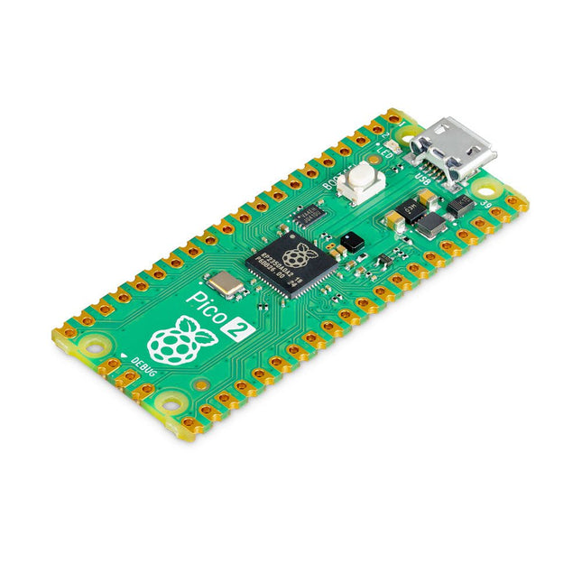
Raspberry Pi Foundation Raspberry Pi Pico 2
The Raspberry Pi Pico 2 is a new microcontroller board from the Raspberry Pi Foundation, based on the RP2350. It features a higher core clock speed, double the on-chip SRAM, double the on-board flash memory, more powerful Arm cores, optional RISC-V cores, new security features, and upgraded interfacing capabilities. The Raspberry Pi Pico 2 offers a significant boost in performance and features while maintaining hardware and software compatibility with earlier members of the Raspberry Pi Pico series. The RP2350 provides a comprehensive security architecture built around Arm TrustZone for Cortex-M. It incorporates signed boot, 8 KB of antifuse OTP for key storage, SHA-256 acceleration, a hardware TRNG, and fast glitch detectors. The unique dual-core, dual-architecture capability of the RP2350 allows users to choose between a pair of industry-standard Arm Cortex-M33 cores and a pair of open-hardware Hazard3 RISC-V cores. Programmable in C/C++ and Python, and supported by detailed documentation, the Raspberry Pi Pico 2 is the ideal microcontroller board for both enthusiasts and professional developers. Specifications CPU Dual Arm Cortex-M33 or dual RISC-V Hazard3 processors @ 150 MHz Memory 520 KB on-chip SRAM; 4 MB on-board QSPI flash Interfaces 26 multi-purpose GPIO pins, including 4 that can be used for AD Peripherals 2x UART 2x SPI controllers 2x I²C controllers 24x PWM channels 1x USB 1.1 controller and PHY, with host and device support 12x PIO state machines Input power 1.8-5.5 V DC Dimensions 21 x 51 mm Downloads Datasheet (Pico 2) Datasheet (RP2350)
-
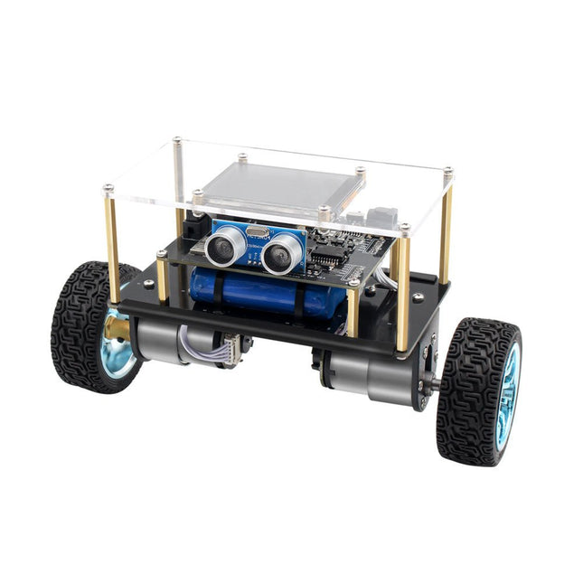
Elektor Labs Elektor Mini-Wheelie Self-Balancing Robot
Arduino-compatible, ESP32-controlled, 2-wheeled Balancing Robot The Elektor Mini-Wheelie is an experimental autonomous self-balancing robot platform. Based on an ESP32-S3 microcontroller, the self-balancing robot is fully programmable using the Arduino environment and open-source libraries. Its wireless capabilities allow it to be controlled remotely over Wi-Fi, Bluetooth or ESP-NOW or to communicate with a user or even another robot. An ultrasonic transducer is available for detecting obstacles. Its color display can be used for displaying cute facial expressions or, for the more down-to-earth users, cryptic debug messages. The robot comes as a neat kit of parts that you must assemble yourself. Everything is included, even a screwdriver. Note: The Mini-Wheelie is an educational development platform intended for learning, experimentation, and robotics development. It is not classified as a toy for children, and its features, documentation, and intended audience reflect this purpose. The product is aimed at students, educators, and developers who wish to explore robotics, programming, and hardware integration in an educational setting. Specifications ESP32-S3 microcontroller with Wi-Fi and Bluetooth MPU6050 6-axis Inertial Measurement Unit (IMU) Two independently controlled 12 V electric motors with tachometer Ultrasonic transducer 2.9" TFT color display (320 x 240) MicroSD card slot Battery power monitor 3S rechargeable Li-Po battery (11.1 V/2200 mAh) Battery charger included Arduino-based open-source software Dimensions (W x L x H): 23 x 8 x 13 cm Included 1x ESP32-S3 Mainboard + MPU6050 module 1x LCD board (2.9 inch) 1x Ultrasonic sensor 1x Battery pack (2200 mAh) 1x Battery charger 1x Motor tyre kit 1x Case board 1x Acrylic board 1x Screwdriver 1x Protective strip 1x Flex cable B (8 cm) 1x Flex cable A (12 cm) 1x Flex cable C 4x Copper column A (25 mm) 4x Copper column B (55 mm) 4x Copper column C (5 mm) 2x Plastic nylon column 8x Screws A (10 mm) 24x Screws B (M3x5) 8x Nuts 24x Metal washers 2x Zip tie 1x MicroSD card (32 GB) Downloads Documentation
-
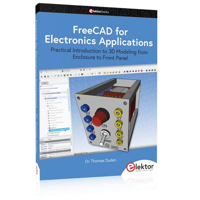
Elektor Publishing FreeCAD for Electronics Applications
Practical Introduction to 3D Modeling from Enclosure to Front Panel Embedding a vintage component, creating a professional looking home for a circuit board, or even designing a complex apparatus complete with a chassis – these and many other challenges turn into a stimulating pleasure with FreeCAD. Once you have internalized the basic processes, there are virtually no limits to your imagination. Starting to use a new software is never straightforward – especially with a tool as versatile as FreeCAD. Manageable, but at the same time easily usable individual components provide the starting point in this book. Putting these components together later results in assemblies. In the FreeCAD universe, a workable trajectory is demonstrated. The described procedure is illustrative so the examples are easily applied to custom tasks. The devices were made by the author and illustrated with photos. Creating a 3D design is requiring some effort but the initial investment pays off soon. Besides the impressive spatial representation of the projects, the extracted drawings yield a solid base for documentation and production. Extended FreeCAD capabilities like the unfolding of sheet metal parts enormously add to efficiency and pushes models forward into practical assembly. Soon you will definitely not want to do without FreeCAD!
€ 44,95
Members: € 40,46
-

FNIRSI FNIRSI LC1020E High Precision LCR Meter
The FNIRSI LC1020E High-Precision LCR Meter with ESR tester is a portable and intelligent solution for testing electronic components, offering a basic accuracy of up to 0.3%. It is ideal for engineers, technicians, and makers. The device supports L/Q, C/D, and R/D measurements using both series and parallel equivalent circuit models, and features a 2.8-inch TFT color display. With preset thresholds and audio-visual alerts, it enables fast pass/fail evaluation, making it perfect for batch testing and quality control. Supporting test frequencies up to 100 kHz, it is well suited for high-frequency analysis of inductors, capacitors, and resistors. Features ±0.05% accuracy with 4.5-digit resolution Automatic R/L/C identification for fast measurements 5 test frequencies (100 Hz–100 kHz) & 3 voltage levels (0.1–0.6 V) Dual display: L/C/R/Z + X/D/Q/θ/ESR Sorting mode & bias voltage for batch testing Dual ports (3-/5-terminal) with 4-wire Kelvin support Data hold & logging for efficient workflow Compact, rechargeable (3000 mAh) – ideal for lab & field use Specifications General Test Frequency 100 Hz, 120 Hz, 1 kHz, 10 kHz, 100 kHz Basic Accuracy 0.3% Display 2.8-inch TFT LCD display Display Digits Main Parameter: 4.5 digits Secondary Parameter: 4.5 digits Measurement Parameters Main Parameters: AUTO/R/C/L/Z Secondary Parameters: X/D/Q/θ/ESR Measurement Range L: 0-100H C: 0-100mF R: 0-10M Internal Bias 0.0 V, 0.5 V Test Level 0.1 V, 0.3 V, 0.6 V Calibration Functions Open circuit calibration, Short circuit calibration Comparison Function Used to calculate the relative error between the component measurement value and the nominal value, displayed as a percentage, and provides filtering results. Nominal values and tolerance can be set, with tolerance range adjustable from 0.1% to 99.9% Function Record Checks if the measured component data meets the set nominal value and tolerance, recording the number of successful and failed measurements Test Terminal Configuration Three-terminal, Five-terminal Output Impedance 100Ω Interface USB-C (Virtual serial port) Others Language settings, Screen brightness, Sound settings, Auto power-off, Calibration settings, System information Battery 3000 mAh Lithium battery Dimensions 18.5 x 8.5 x 3.5 cm Weight 680 g Capacitance (C) Range: 1mF-100mF 100 Hz: 5% ±5 digits 1 kHz: 3% ±5 digits 10 kHz: / 100 kHz: / Range: 1uF-1mF 100 Hz: 1% ±4 digits 1 kHz: 0.5% ±5 digits 10 kHz: 2% ±5 digits 100 kHz: 3% ±4 digits Range: 1nF-1uF 100 Hz: / 1 kHz: 0.3% ±2 digits 10 kHz: 0.4% ±2 digits 100 kHz: 1% ±4 digits Range: 1pF-1nF 100 Hz: / 1 kHz: 2% ±2 digits 10 kHz: 1.5% ±2 digits 100 kHz: 2% ±4 digits Inductance (L) Range: 1H-100H 100 Hz: 2% ±5 digits 1 kHz: 2% ±5 digits 10 kHz: / 100 kHz: / Range: 1mH-1H 100 Hz: 0.4% ±5 digits 1 kHz: 0.3% ±2 digits 10 kHz: 0.4% ±3 digits 100 kHz: 2.5% ±5 digits Range: 10uH-1mH 100 Hz: 3% ±5 digits 1 kHz: 0.5% ±4 digits 10 kHz: 0.5% ±3 digits 100 kHz: 1.5% ±5 digits Range: 1uH-10uH 100 Hz: / 1 kHz: 2% ±5 digits 10 kHz: 2% ±5 digits 100 kHz: 4% ±5 digits Resistance (R) Range: 1MΩ-10MΩ 100 Hz: 5% ±4 digits 1 kHz: 3% ±3 digits 10 kHz: / 100 kHz: / Range: 1KΩ-1MΩ 100 Hz: 0.4% ±4 digits 1 kHz: 0.2% ±2 digits 10 kHz: 0.3% ±3 digits 100 kHz: 0.6% ±5 digits Range: 1Ω-1KΩ 100 Hz: 1.5% ±4 digits 1 kHz: 0.3% ±2 digits 10 kHz: 0.3% ±3 digits 100 kHz: 0.6% ±5 digits Range: 10mΩ-1Ω 100 Hz: 4% ±4 digits 1 kHz: 2% ±5 digits 10 kHz: 2% ±5 digits 100 kHz: 5% ±5 digits Included 1x FNIRSI LC1020E LCR Meter 1x Kelvin Test Clip 2x Test Leads (1x black, 1x red) 1x Shorting Plate 1x USB-C Cable 1x Manual Downloads Manual Firmware V1.1
€ 84,95€ 69,95
Best Price
-

Elektor Bundles 555 Timer Projects (Bundle)
This bundle is all about designing projects based on the 555 timer IC. The book features over 45 fully tested and documented projects. Together with the kit, which contains more than 130 through-hole components, you can build all the projects described on a breadboard. The setup also makes it easy to modify and experiment with the projects. Over 45 Builds for the Legendary 555 Chip (and the 556, 558) Some of the projects in the book are: Alternately Flashing Two LEDs Changing LED Flashing Rate Touch Sensor On/Off Switch Switch On/Off Delay Light-Dependent Sound Dark/Light Switch Tone Burst Generator Long Duration Timer Chasing LEDs LED Roulette Game Traffic Lights Continuity Tester Electronic Lock Switch Contact Debouncing Toy Electronic Organ Multiple Sensor Alarm System Metronome Voltage Multipliers Electronic Dice 7-Segment Display Counter Motor Control 7-Segment Display Dice Electronic Siren Various Other Projects Kit Contents Resistors 1x 15 kΩ 1x 68 kΩ 2x 47 kΩ 1x 82 kΩ 2x 820 Ω 1x 8.2 kΩ 3x 10 kΩ 1x 1.8 kΩ 1x 6.8 kΩ 14x 2.2 kΩ 10x 680 Ω 1x 27 kΩ 1x 5.6 kΩ 1x 560 kΩ 1x 4.7 kΩ 1x 3.3 kΩ 3x 33 kΩ 1x 36 kΩ 2x 100 kΩ 5x 1 kΩ 1x 3.9 kΩ 2x 56 kΩ 2x 12 kΩ 1x 10 kΩ potentiometer 1x 1 MΩ potentiometer 2x 50 kΩ potentiometer 3x 20 kΩ potentiometer 1x 10 kΩ potentiometer 1x 10 kΩ potentiometer 1x 50 kΩ potentiometer 1x 100 kΩ potentiometer 1x 50 kΩ potentiometer Capacitors 1x 0.33 μF 1x 1 μF 1x 10 nF 1x 22 nF 1x 47 nF 1x 100 nF 1x 10 μF electrolytic 1x 33 μF electrolytic 2x 100 μF electrolytic LEDs 10x 5 mm red LED 10x 3 mm red LED 3x 3 mm yellow LED 3x 3 mm green LED 1x Common-cathode 7-segment LED Semiconductors 3x 555 timer 1x CD4017 counter 1x CD4026 counter 1x CD4011 NAND gate 4x 1N4148 diode 1x IRFZ46N MOSFET 1x Thermistor 1x Light dependent resistor (LDR) Miscellaneous 1x Passive buzzer 1x Active buzzer 1x SG90 servo 1x 8 Ω mini loudspeaker 1x 9 V DC brushed motor 1x 5 V relay 1x 9 V battery clip 7x Pushbutton switches 1x Breadboard 1x Breadboard jumper wires
€ 69,95€ 54,95
Best Price
-
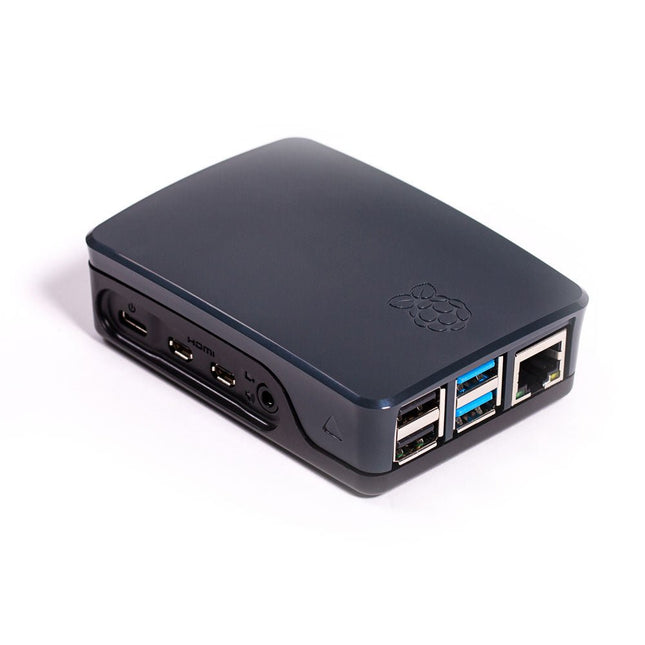
Raspberry Pi Foundation Official Case for Raspberry Pi 4 (black/gray)
Official Case for Raspberry Pi 4 (black/gray)
-

Raspberry Pi Foundation Raspberry Pi Debug Probe
The Raspberry Pi Debug Probe is an all-in-one USB-to-debug kit that provides all the necessary hardware and cables for easy, solderless, plug-and-play debugging. It features both a processor serial debug interface (by default the ARM Serial Wire Debug interface, but other interfaces can be supported) and an industry-standard UART interface. Both interfaces use the Raspberry Pi 3-pin debug connector. It is designed to make it easy to debug and program Raspberry Pi Pico and RP2040 with a range of host platforms including Windows, Mac, and typical Linux computers. While designed for use with Raspberry Pi products, the Debug Probe provides standard UART and CMSIS-DAP interfaces over USB, so it can also be used with other processors, or even just as a USB-to-UART cable. It works with OpenOCD and other tools that support CMSIS-DAP. The Debug Probe is based on Raspberry Pi Pico hardware and runs the open source Raspberry Pi Pico Probe software. The firmware is updated in the same way as Raspberry Pi Pico firmware, so it is easy to keep the unit up to date with the latest firmware, or to use custom firmware. Features USB to ARM Serial Wire Debug (SWD) port USB to UART bridge Compatible with the CMSIS-DAP standard Works with OpenOCD and other tools supporting CMSIS-DAP Open source, easily upgradeable firmware Specifications Dimensions: 22 x 32 mm Nominal I/O voltage: 3.3 V Operating temperature: -20°C to +70°C Included 1x Raspberry Pi Debug Probe 1x Plastic case 1x USB cable 3x Debug cables 3-pin JST connector to 3-pin JST connector cable 3-pin JST connector to 0.1-inch header (female) 3-pin JST connector to 0.1-inch header (male) Downloads Datasheet 3-pin Debug Connector Schematics Diagram Latest Firmware
-
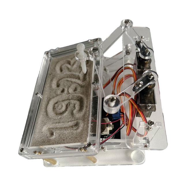
Elektor Labs Elektor Sand Clock for Raspberry Pi Pico
Raspberry Pi-based Eye Catcher A standard sand clock just shows how time passes. In contrast, this Raspberry Pi Pico-controlled sand clock shows the exact time by “engraving” the four digits for hour and minute into the layer of sand. After an adjustable time the sand is flattened out by two vibration motors and everything begins all over again. At the heart of the sand clock are two servo motors driving a writing pen through a pantograph mechanism. A third servo motor lifts the pen up and down. The sand container is equipped with two vibration motors to flatten the sand. The electronic part of the sand clock consists of a Raspberry Pi Pico and an RTC/driver board with a real-time clock, plus driver circuits for the servo motors. A detailed construction manual is available for downloading. Features Dimensions: 135 x 110 x 80 mm Build time: approx. 1.5 to 2 hours Included 3x Precut acrylic sheets with all mechanical parts 3x Mini servo motors 2x Vibration motors 1x Raspberry Pi Pico 1x RTC/driver board with assembled parts Nuts, bolts, spacers, and wires for the assembly Fine-grained white sand
€ 49,95€ 39,95
Best Price
-

Elektor Publishing The Book of 555 Timer Projects
Over 45 Builds for the Legendary 555 Chip (and the 556, 558) The 555 timer IC, originally introduced by the Signetics Corporation around 1971, is sure to rank high among the most popular analog integrated circuits ever produced. Originally called the IC Time Machine, this chip has been used in many timer-related projects by countless people over decades. This book is all about designing projects based on the 555 timer IC. Over 45 fully tested and documented projects are presented. All projects have been fully tested by the author by constructing them individually on a breadboard. You are not expected to have any programming experiences for constructing or using the projects given in the book. However, it’s definitely useful to have some knowledge of basic electronics and the use of a breadboard for constructing and testing electronic circuits. Some of the projects in the book are: Alternately Flashing Two LEDs Changing LED Flashing Rate Touch Sensor On/Off Switch Switch On/Off Delay Light-Dependent Sound Dark/Light Switch Tone Burst Generator Long Duration Timer Chasing LEDs LED Roulette Game Traffic Lights Continuity Tester Electronic Lock Switch Contact Debouncing Toy Electronic Organ Multiple Sensor Alarm System Metronome Voltage Multipliers Electronic Dice 7-Segment Display Counter Motor Control 7-Segment Display Dice Electronic Siren Various Other Projects The projects given in the book can be modified or expanded by you for your very own applications. Electronic engineering students, people engaged in designing small electronic circuits, and electronic hobbyists should find the projects in the book instructive, fun, interesting, and useful.
€ 34,95
Members: € 31,46
-

Generic LC Meter Kit
This LC meter kit is an easy-to-build, educational, and entertaining DIY project for measuring the inductance (L) of coils and inductors, the capacitance (C) of capacitors, other passive components and the frequency of signals. Specifications Power supply USB DC 5 V Capacitance measurement range of small non-polarized capacitors 1 pF~2200 pF Capacitance measurement range of electrolytic capacitors 1 µF~12000 µF Inductance measurement range 1 µH~1 H Frequency measurement range 20 Hz~400 kHz Dimensions (PCB) 91 x 80 mm Dimensions (Shell) 106 x 91 x 28 mm Included Doubled-sided PCB All required components incl. LCD display Six pre-cut transparent acrylic plates Screws and nuts
-

Elektor Bundles Arduino UNO Q (Bundle)
This bundle includes the Arduino UNO Q (2 GB) and the new book "Arduino UNO Q and AI". The Arduino UNO Q is the first UNO board with a hybrid dual-brain architecture, combining a powerful Linux processor with a real-time microcontroller – bringing advanced computing and precise control together on one board. Powered by a Qualcomm Dragonwing QRB2210 MPU running Debian Linux and a STM32U585 MCU for real-time tasks, the UNO Q is built for next-generation applications. From Edge Computing and AI to robotics and automation, it delivers high performance without sacrificing ease of use. Simply connect your peripherals and get started – no extra hardware required. Features Dual-core architecture: Linux MPU + real-time MCU Qualcomm Dragonwing QRB2210 with Debian Linux support STM32U585 microcontroller for deterministic control Runs Arduino sketches via Zephyr OS Ideal for AI, IoT, robotics, and industrial projects Specifications Microprocessor (MPU) Qualcomm Dragonwing QRB2210:Quad-core Arm Cortex-A53 @ 2.0 GHzAdreno GPU 3D graphics accelerator2× ISP (13 MP + 13 MP or 25 MP) @ 30 fps Microcontroller (MCU) STM32U585Arm Cortex-M33 up to 160 MHz2 MB flash memory786 KB SRAM RAM 2 GB LPDDR4 Power Supply From USB-C connector 5 V max at 3 AInput Voltage (VIN): 7-24 V Storage 16 GB eMMC USB 1× USB-C port with host/device role switching, power role switch and video output Connectivity Wi-Fi 5 (2.4/5 GHz) with onboard antennaBluetooth 5.1 with onboard antenna Interfaces I²C/I³CSPIPWMCANUARTPSSIGPIOJTAGADC Video Video output support via USB-CMIPI DSI pins on JMEDIA header Extra 4× RGB user-controllable LEDs8×13 Blue LED Matrix1× Qwiic connector voltage 3V3, I²C1× User push-buttonJCTL: MPU Remote Debug connector Audio Microphone IN / Headphone OUT / Line OUT on JMISC MPU Operating System Linux Debian OS with upstream support Real-time Operating System Arduino Core on Zephyr OS Containerization Docker and Docker Compose support Support Operating Systems for Arduino App Lab Windows: Windows 10 or later (64-bit)macOS: macOS 11 or later (64-bit)Linux: Ubuntu 22.04 or later, and Debian Trixie (64-bit) Dimensions 68.85 × 53.34 mm (UNO form factor) Downloads Datasheet User Manual Pinout Schematics Book: Arduino UNO Q and AI – Learn to Build Intelligent Embedded Systems Build smarter embedded systems with Arduino UNO Q. This book gives you the tools, knowledge, and confidence to turn ideas into intelligent, working solutions using the Arduino UNO Q platform. Discover how to build intelligent embedded systems with the Arduino UNO Q and AI. Unlock the full potential of the Arduino UNO Q, a next-generation platform that combines the real-time power of the STM32U585 microcontroller with the flexibility of a Qualcomm Dragonwing QRB2210 microprocessor. Learn how to rapidly prototype real-world applications using the Arduino IDE for low-level embedded control and Python in Arduino App Lab for high-level development. Build confidence through hands-on projects that guide you step by step from basic board features to complete working systems. Explore ready-to-use, AI based Arduino App Lab examples and see how they can jump-start your development and reduce time to deployment. Step into the world of Edge AI with a clear, practical introduction to Edge Impulse Studio—no prior AI experience required. Follow a complete, real-world workflow to create a Keyword Spotting AI application, covering data collection, model training, optimization, and on-device inference using the Edge Impulse Studio. Bridge the gap between embedded systems and machine learning and learn how to bring intelligence directly onto your hardware. Perfect for embedded engineers, educators, students, and makers looking to stay ahead in AI-enabled product development. This bundle contains: Arduino UNO Q (2 GB) (normal price: €50) Book: Arduino UNO Q and AI (normal price: €35)
€ 84,95€ 69,95
Best Price
-
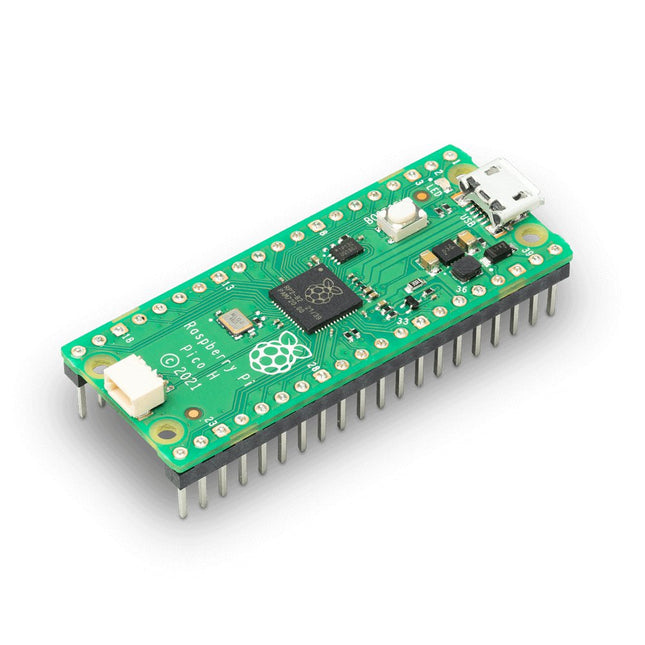
Raspberry Pi Foundation Raspberry Pi Pico H
Raspberry Pi Pico is a low-cost, high-performance microcontroller board and also the first product based on a chip developed by Raspberry Pi itself. The RP2040 microcontroller chip ('Raspberry Silicon') offers a dual-core ARM Cortex-M0+ processor (133 MHz), 256 KB RAM, 30 GPIO pins, and many other interface options. In addition, there is 2 MB of on-board QSPI flash memory for code and data storage. Specifications RP2040 microcontroller chip designed by Raspberry Pi in the UK Dual-core ARM Cortex M0+ processor, with a flexible clock running up to 133 MHz 264 kB SRAM, and 2 MB on-board Flash memory Castellated module allows soldering directly to carrier boards USB 1.1 host and device support Energy-efficient sleep and dormant modes Drag and drop programming using mass storage via USB 26x multifunction GPIO pins 2x SPI, 2x I²C, 2x UART, 3x 12-bit ADC, 16x controllable PWM channels On-chip accurate clock and timer Temperature sensor On-chip accelerated floating point libraries 8x programmable IO (PIO) state machines for custom peripherals H version of the Raspberry Pi Pico board with pre-soldered headers and 3-pin debug connector Downloads Specifications of 3-pin Debig Connector


