Physical Products
-
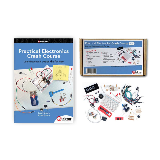
Elektor Bundles Practical Electronics Crash Course (Bundle)
Getting started in electronics is not as difficult as you may think. With this bundle (book + kit of parts), you can explore and learn the most important electrical and electronics engineering concepts in a fun way by doing various experiments. You will learn electronics practically without getting into complex technical jargon and long calculations. As a result, you will be creating your own projects soon. This kit contains the components required to build most of the detailed examples of the book on a breadboard and try them out for real. The kit can, of course, also be used without the book for building other circuits and doing your own experiments. Kit contents 1x 39 Ω, 1 W resistor 1x 47 Ω resistor 1x 180 Ω resistor 1x 330 Ω resistor 3x 1 kΩ resistor 1x 2.2 kΩ resistor 1x 3.9 kΩ resistor 1x 6.8 kΩ resistor 1x 10 kΩ resistor 1x 15 kΩ resistor 1x 22 kΩ resistor 1x 33 kΩ resistor 1x 47 kΩ resistor 1x 56 kΩ resistor 1x 82 kΩ resistor 1x 120 kΩ resistor 1x 680 kΩ resistor 2x 100 kΩ resistor 1x 10 kΩ trimmer 1x 10 kΩ linear potentiometer 1x 100 kΩ linear potentiometer 1x LDR 1x 1 nF ceramic capacitor 2x 10 nF ceramic capacitor 1x 100 nF ceramic capacitor 1x 1 µF, 25 V aluminium electrolytic capacitor 2x 10 µF, 25 V aluminium electrolytic capacitor 1x 100 µF, 25 V aluminium electrolytic capacitor 1x 470 µF, 25 V aluminium electrolytic capacitor 1x 1000 µF, 25 V aluminium electrolytic capacitor 1x RGB LED, Common-Cathode (CC) 1x 1N4148 small signal diode 1x 1N4733A 5.1 V, 1 W Zener diode 3x LED, red 2x BC337 NPN transistor 1x IRFZ44N N-channel MOSFET 2x NE555 timer 1x LM393 comparator 1x 74HCT08 quad AND gate 3x Tactile switch 2x SPDT switch 1x Relay, SPDT, 9 VDC 1x Active buzzer 1x Passive buzzer 50 cm Solid wire, 16 AWG, unjacketed 2x PP3 9 V battery clip 1x Breadboard 20x Jumper wire This bundle contains: Practical Electronics Crash Course Kit (valued at: €45) Book: Practical Electronics Crash Course (normal price: €45)
€ 89,95€ 69,95
Best Price
-

Raspberry Pi Foundation Official Raspberry Pi USB-C Adapter (black)
This small adapter allows you to convert an existing micro USB power supply into a USB-C power supply.
-
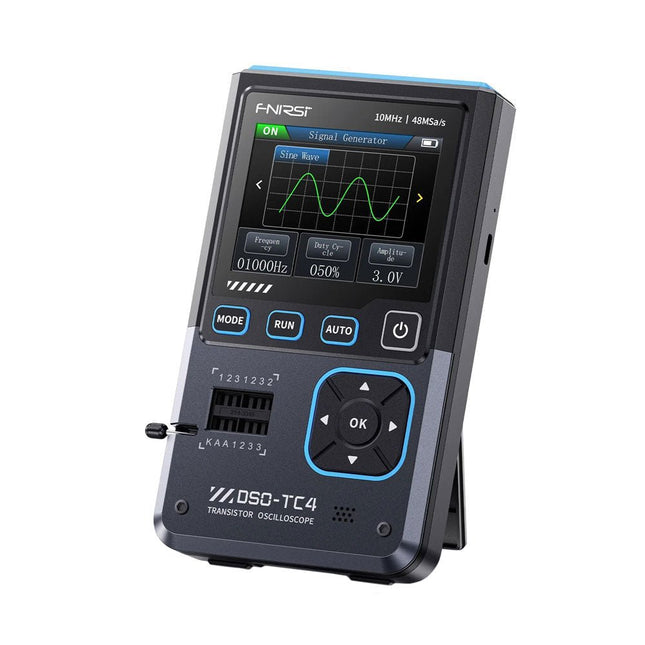
FNIRSI FNIRSI DSO-TC4 (3-in-1) Oscilloscope (10 MHz) + Transistor Tester + Signal Generator
The FNIRDSI DSO-TC4 is a multifunctional transistor oscilloscope that is both comprehensive and practical. It is designed for use in maintenance and R&D applications, integrating an oscilloscope, transistor tester, and signal generator into a single device. Features Equipped with a 2.8-inch TFT color screen for a clear and intuitive display Built-in high-capacity rechargeable lithium battery (1500 mAh) with a standby time of up to 4 hours Compact and lightweight, ideal for mobile use Specifications Oscilloscope Analog Bandwidth 10 MHz Real-Time Sampling Rate 48 MSa/s Input Impedance 1 MΩ Coupling Mode AC/DC Test Voltage Range 1:1 Probe: 80 Vpp (+40 V) 10:1 Probe: 800 Vpp (+400 V) Vertical Sensitivity 10 mV/div~10 V/div (X1 range) Vertical Displacement Adjustable with indication Time Base Range 50ns~20s Trigger Mode Auto/Normal/Single Trigger Type Rising edge, Falling edge Trigger Level Adjustable with indication Waveform Freeze Yes (HOLD function) Automatic Measurement Max, Min, Avg, RMS, Vpp, Frequency, Cycle, Duty Cycle Component Tester Transistor Amplification factor "hfe"; Base-Emitter voltage "Ube", Ic/Ie, Collector-Emitter reverse leakage current "Iceo", Ices, Forward voltage drop of protection diode "Uf" Diode Forward voltage drop <5 V (Forward voltage drop, Junction capacitance, Reverse leakage current) Zener Diode 0.01~32 V Reverse Breakdown Voltage (K-A-A Test Area) Field-Effect Transistor (FET) JFET: Gate capacitance "Cg", Drain current Id under "Vgs", Forward voltage drop of protection diode "Uf" IGBT: Drain current Id under Vgs, Forward voltage drop of protection diode Uf MIOSTET: Threshold voltage "Vt", Gate capacitance "Cg", Drain-Source resistance "Rds", Forward voltage drop of protection diode "Uf" Unidirectional SCR Trigger voltage <5V, Gate level (Gate voltage) Bidirectional SCR Trigger current <6mA (Gate voltage) Capacitor 25pF~100mF, Capacitance value, Loss factor "Vloss" Resistor 0.01Ω~50MΩ Inductor 10μH~1000μH, DC resistance DS18B20 Temperature sensor, Pins: GND, DQ, VDD DHT11 Temperature and humidity sensor, Pins: VDD, DATA, GND Signal Generator Output Waveform Supports 13 waveform outputs Waveform Frequency 0-50 KHz Square Wave Duty Cycle 0-100% Waveform Amplitude 0.1-3.0 V General Display 2.8-inch TFT color screen Backlight Brightness adjustable Power Supply USB-C (5 V/1 A) Battery 3.7 V/1500 mAh Languages English, German, Spanish, Portuguese, Russian, Chinese, Japanese, Korean Dimensions 90 x 142 x 27.5 mm Weight 186 g Included 1x FNIRSI DSO-TC4 (3-in-1) Oscilloscope (10 MHz) 1x P6100 Oscilloscope probes (10X) 1x Alligator clip probe 3x Test hooks 1x Adapter 1x USB-C charging cable 1x Manual Downloads Manual Firmware V0.0.7 (+V1.0.9)
€ 89,95€ 74,95
Best Price
-
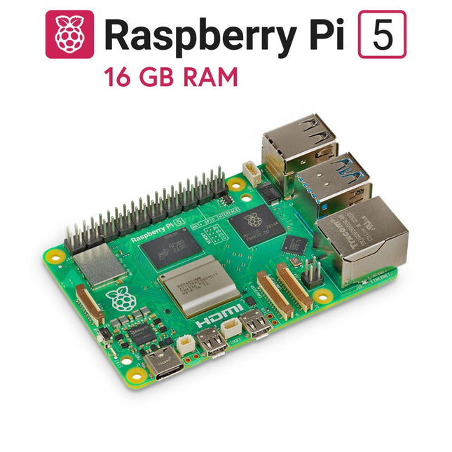
Raspberry Pi Foundation Raspberry Pi 5 (16 GB RAM)
The Raspberry Pi 5 delivers more performance than ever before. Thanks to the faster CPU, GPU and RAM, Raspberry Pi 5 is up to 3x faster than its already fast predecessor. In addition to the speed boost, the Raspberry Pi 5 (which features the new Raspberry Pi RP1 silicon for advanced I/O capabilities) also offers the following features for the first time ever: RTC, an on/off button and a PCIe interface. Features 64-bit quad-core ARM Cortex-A76 processor (2.4 GHz) VideoCore VII GPU (800 MHz) 16 GB of LPDDR4X RAM (4267 MHz) Raspberry Pi silicon RP1 I/O controller chip Real-time clock On/off button PCIe 2.0 UART connector Fan connector Specifications SoC Broadcom BCM2712 CPU ARM Cortex-A76 (ARM v8) 64-bit Clock speed 4x 2.4 GHz GPU VideoCore VII (800 MHz) RAM 16 GB LPDDR4X (4267 MHz) WiFi IEEE 802.11b/g/n/ac (2.4 GHz/5 GHz) Bluetooth Bluetooth 5.0, BLE Ethernet Gigabit Ethernet (with PoE+ support) USB 2x USB-A 3.0 (5 GBit/s)2x USB-A 2.0 PCI Express 1x PCIe 2.0 GPIO Standard 40-pin GPIO header Video 2x micro-HDMI ports (4K60)2x 4-lane MIPI (DSI/CSI) Multimedia H.265 (4K60 decode)OpenGL ES 3.1, Vulkan 1.2 SD card microSD Power 5 V/5 A (via USB-C)Power over Ethernet (PoE+) Raspberry Pi 5 2 GB RAM 4 GB RAM 8 GB RAM Downloads Datasheet Unboxing the Raspberry Pi 5 First Insights
-

Zhongdi ZD-153A Solder Fume Extractor
Fumes released during the soldering process are potentially harmful to health. This solder fume extractor is securely fastened to the work table with a bracket. Thanks to the 3 axes, the solder fume extractor can be positioned perfectly, i.e. directly above the rising solder fumes. The harmful solder fumes are extracted by a powerful but quiet fan and filtered by an activated-carbon filter mat. Features Removes solder fumes Absorbs toxic gases and fumes from brazing operations Helps reduce the likelihood of headaches, eye irration and neusea Adjustable absorption angle for accurate placement Easy replaceable activated carbon filter High-performance fan Low noise and long life service Specifications Absorption capacity: 1 m³/min (max.) Power consumption: 23 W Power supply: 220-240 VAC Amount of activated carbon filter: 7 g Maximum absorption weight: 2 g Dimensions: 220 x 270 x 168 mm (W x H x D) Weight: 1.4 kg
€ 52,95
-
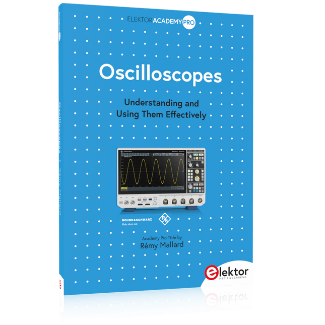
Elektor Publishing Oscilloscopes (Book)
Understanding and Using Them Effectively What happens in electronics is invisible to the naked eye. The instrument that allows to accurately visualize electrical signals, the one through which the effects of electronics become apparent to us, is the oscilloscope. Alas, when one first ventures into electronics, it is often without an oscilloscope. And one is left fumbling, both physically and mentally. Observing an electrical signal on a screen for the first time is a revelation. Nobody wishes to forgo that marvel again. There is no turning back. In electronics, if one wishes to progress with both enjoyment and understanding, an oscilloscope is essential. This marks the beginning of a period of questioning: how to choose one? And no sooner is that question answered than a whole string of others arises, which can be summed up in just one: how does one use the oscilloscope in such a way that what it displays truly reflects the reality of the signals? Rémy Mallard is a passionate communicator with a gift for making complex technical subjects understandable and engaging. In this book, he provides clear answers to essential questions about using an oscilloscope and offers a wealth of guidance to help readers explore and understand the electrical signals behind electronic systems. With his accessible style and practical insights, this book is a valuable tool for anyone eager to deepen their understanding of electronics.
€ 44,95
Members: € 40,46
-

QuantAsylum QuantAsylum QA403 24-bit Audio Analyzer
The QA403 is QuantAsylum's fourth-generation audio analyzer. The QA403 extends the functionality of the QA402 with improved noise and distortion performance, in addition to a flatter response at band edges. The compact size of the QA403 means you can take it just about anywhere. Features 24-bit ADC/DAC Up to 192 kS/s Fully isolated from PC Differential Input/Output USB powered Built-in Attenuator Fast Bootup and Driverless The QA403 is a driverless USB device, meaning it’s ready as soon as you plug it in. The software is free and it is quick and easy to move the hardware from one machine to the next. So, if you need to head to the factory to troubleshoot a problem or take the QA403 home for a work-from-home day, you can do it without hassle. No-Cal Design The QA403 comes with a factory calibration in its flash memory, ensuring consistent unit-to-unit performance. On your manufacturing line you can install another QA403 and be confident what you read on one unit will be very similar to the next unit. It is not expected that re-calibration will be required at regular intervals. Measurements Making basic measurements is quick and easy. In a few clicks you will understand the frequency response, THD(+N), gain, SNR and more of your device-under test. Dynamic Range The QA403 offers 8 gain ranges on the input (0 to +42 dBV in 6 steps), and 4 gain ranges on the output (-12 to +18 dBV in 10 dB steps). This ensures consistent performance over very wide ranges of input and output levels. The maximum AC input to the QA403 is +32 dBV = 40 Vrms. The maximum DC is ±40 V, and the maximum ACPEAK + DC = ±56 V. Easy Programmability The QA403 supports a REST interface, making it easy to automate measurements in just about any language you might anticipate. From Python to C++ to Visual Basic—if you know how to load a web page in your favorite language, you can control the QA403 remotely. Measurements are fast and responsive, usually with dozens of commands being processed per second. Isolated and USB Powered The QA403 is isolated from the PC, meaning you are measuring your DUT and not chasing some phantom ground loop. The QA403 is USB powered, like nearly all our instruments. If you are setting up remotely, throw a powered hub in your bag and your entire test setup can be running with a minimum of cables. Goodbye Soundcard, Hello QA403 Tired of trying to make a soundcard work? The calibration nightmare? The lack of gain stages? The limited drive? Are you tired of dealing with the fixed input ranges? The worry that you might destroy it with too much DC or AC? Tired of the ground loops? That’s why QuantAsylum built the QA403. Specifications Dimensions 177 x 44 x 97 mm (W x H x D) Weight 435 g Case Material Powder-coating Aluminum (2 mm thick front panel, 1.6 mm thick top/bottom) Downloads Datasheet Manual GitHub
€ 799,00
Members: € 719,10
-
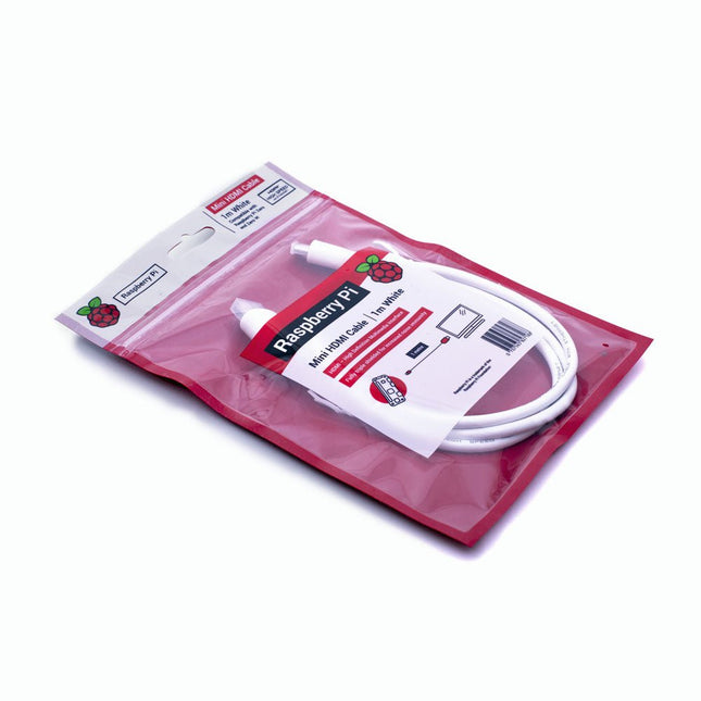
Raspberry Pi Foundation Official Mini-HDMI Cable for Raspberry Pi Zero
The official Raspberry Pi mini-HDMI to HDMI (A/M) cable designed for all Raspberry Pi Zero models. 19-pin HDMI Type D(M) to 19-pin HDMI Type A(M) 1 m cable (white) Nickel-plated plugs 4Kp60 compliant RoHS compliant 3 Mohm 300 VDC insulation, withstands 300 VDC for 0.1s
€ 3,95€ 1,95
Best Price
-
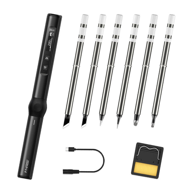
FNIRSI FNIRSI HS-01 Smart Soldering Iron (incl. 6 Soldering Tips)
The perfect tool for quick repairs The FNIRSI HS-01 is a powerful, adjustable smart soldering iron with a built-in 0.87-inch OLED display that quickly reaches temperatures between 80-420°C (180-780°F). The display shows all important information, including the status of the temperature level, the set temperature, the supply voltage and the power percentage. You can set the input voltage from 9-20 V directly in the menu according to your needs. The integrated sleep mode automatically turns off the iron after 30 minutes. Features 96 W input (DC) 65 W PD power OLED display Constant temperature & fast heating CNC metal integral molding Smart safety anti-scald Mini pocket size Ergonomic design Aluminum material Left/right hand switch Efficient heat radiation Inductive sleep Color: Black Specifications Power 65 W Screen 0.87" OLED Operating voltage 9-20 VDC Power supply USB-C Temperature range 80-420°C (180-780°F) Fast charging protocol PD trigger Dimensions 184 x 20 x 20 mm (7.24 x 0.79 x 0.79') Weight 56 g Power Selection Operating voltage 20 V 15 V 12 V 9 V Operating current ≥3.25 A ≥2.5 A ≥2 A ≥1.5 A Power 65 W 37.5 W 24 W 13.5 W Tin melting time 8s 12s 17s 30s Included 1x FNRISI HS-01 smart soldering iron 6x Soldering iron tips (HS01-BC2, HS01-KR, HS01-K65, HS01-B2, HS01-ILS, HS01-BC3) 1x DC to USB-C power cable 1x Mini soldering iron stand 1x Manual Required Power adapter USB-C cable Downloads Manual Firmware V0.3.s19
€ 82,00
-
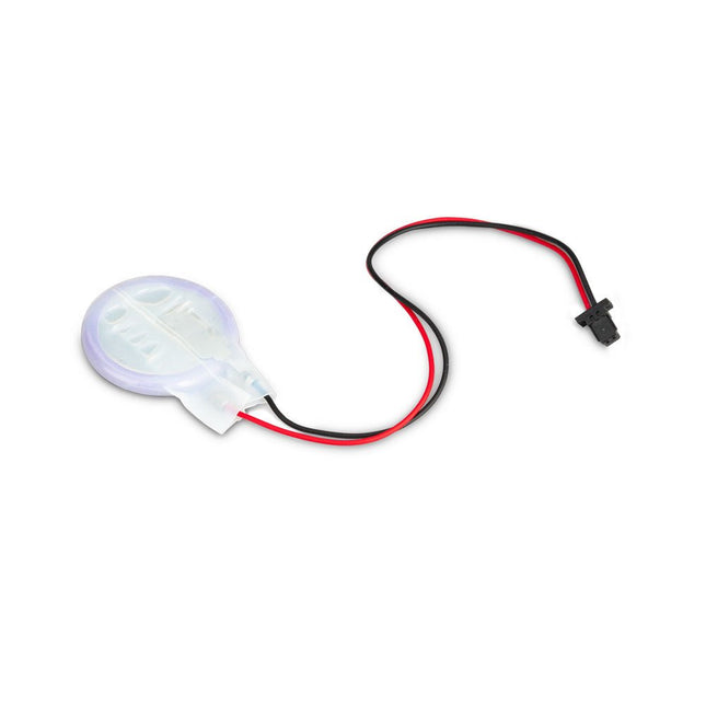
Raspberry Pi Foundation RTC Battery for Raspberry Pi 5
The power-management IC used on Raspberry Pi 5 integrates a real-time clock, and charging circuitry for a button cell which can power the clock while main power is disconnected. This Panasonic ML-2020 lithium manganese dioxide battery with a two-pin plug and a double-sided adhesive pad can be connected directly to the battery connector of the Raspberry Pi 5 and attached to the inside of a case or another convenient location.
-
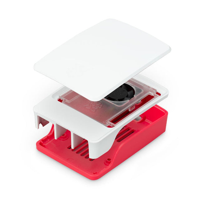
Raspberry Pi Foundation Official Case for Raspberry Pi 5 (white/red)
The Raspberry Pi 5 case is a refinement of the Raspberry Pi 4 case with improved thermal features to support the higher peak power consumption of the Raspberry Pi 5. It integrates a variable speed fan that is powered and controlled via a dedicated connector on the Raspberry Pi 5.
-

Elektor Classics The Elektor Arduino Collection (USB Stick)
This USB Stick contains more than 300 Arduino-related articles published in Elektor Magazine. The content includes both background articles and projects on the following topics: Software & hardware development: Tutorials on Arduino software development using Arduino IDE, Atmel Studio, Shields, and essential programming concepts. Learning: The Microcontroller Bootcamp offers a structured approach to programming embedded systems. Data acquisition & measurement: Projects such as a 16-bit data logger, lathe tachometer, and an AC grid analyzer for capturing and analyzing real-time signals. Wireless communication: Learn how to implement wireless networks, create an Android interface, and communicate effectively with microcontrollers. Robotics and automation: This covers the Arduino Nano Robot Controller, supporting boards for automation, and explores various Arduino shields to enhance functionality. Self-build projects: Unique projects such as laser projection, Numitron clock and thermometer, ELF receiver, Theremino, and touch LED interfaces highlight creative applications. Whether you're a beginner or an experienced maker, this collection is a valuable resource for learning, experimenting, and pushing the boundaries of Arduino technology.
€ 49,95€ 34,95
Best Price
-
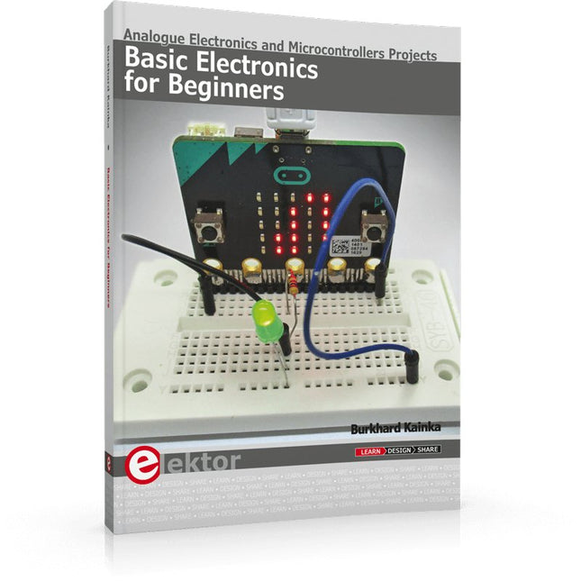
Elektor Publishing Basic Electronics for Beginners
Analogue Electronics and Microcontrollers Projects Hobbyist electronics can be a fun way to learn new skills that can be helpful to your career. Those who understand the basics of electronics can design their own circuits and projects. However, before you run, you need to learn to walk. It all starts with analogue electronics. You should be familiar with the simple components and circuits and understand their basic behaviors and the issues you may encounter. The best way to do this is through real experiments. Theory alone is not enough. This book offers a large number of practical entry-level circuits, with which everyone can gain the basic experience. Through the widespread introduction of microcontrollers, a new chapter in electronics has begun. Microcontrollers are now performing more and more tasks that were originally solved using discrete components and conventional ICs. Starting out has become easier and easier thanks to platforms including Bascom, Arduino, micro:bit. The book introduces numerous manageable microcontroller applications. It’s now a case of less soldering and more programming.
€ 39,95
Members: € 35,96
-

Elektor Bundles Elektor Raspberry Pi Pico Advanced Kit (Bundle)
Comprehensive Book-Hardware Bundle for the RP2040 Microcontroller with over 80 Projects Unlock the potential of modern controller technology with the Raspberry Pi Pico in this bundle. Perfect for both beginners and experienced users, the easy-to-follow guide takes you from the basics of electronics to the complexities of digital signal processing. With the Raspberry Pi Pico, the dedicated hardware kit and MicroPython programming, you will learn the key principles of circuit design, data collection, and processing. Get hands-on with over 80 projects like a stopwatch with an OLED display, a laser distance meter, and a servo-controlled fan. These projects are designed to help you apply what you've learned in real-world scenarios. The book also covers advanced topics like wireless RFID technology, object detection, and sensor integration for robotics. Whether you're looking to build your skills in electronics or dive deeper into embedded systems, this bundle is the perfect resource to help you explore the full potential of the Raspberry Pi Pico. Contents of the Bundle 1x Project Book (273 pages) 1x Raspberry Pi Pico H 1x Smart Car Kit Electronic Parts 2x Solderless breadboard (400 holes) 1x Solderless breadboard (170 holes) 5x Colorful 5 mm LEDs (green, red, blue, yellow and white) 1x Laser transmitter 1x Passive buzzer 1x Micro USB cable (30 cm) 1x 65 Jumper wires 1x 20 cm male to female Dupont wire 1x Clear case 1x Magnet (diameter: 8 mm, thickness: 5 mm) 1x Rotary potentiometer 10x 2 KΩ resistors 2x M2.5x30 mm copper pillars 10x Phillips pan head screws 10x M2.5 nickel hex nuts 1x 2-inch dual-purpose screwdriver Modules 1x RGB module 1x 9G servo 1x Dual-axis XY joystick module 1x RC522 RFID module 1x 4 Bits digital LED display module 1x Traffic light display module 1x Rotary Encoder module 1x 1602 LCD Display module (Blue) 1x Photoresistor module 1x DC motor with male Dupont wire 1x Fan blade 1x Raindrops module 1x OLED module 1x Membrane switch keyboard 1x Mini magnetic spring module 1x Infrared remote control 1x Infrared receiver module 1x DC stepper motor driver board 1x Button Sensors 1x Vibration sensor 1x Soil moisture sensor 1x Sound sensor 1x Mini PIR motion sensor 1x Temperature & Humidity sensor 1x Flame sensor 2x Crash sensor 2x Tracking sensor 1x Ultrasonic sensor
€ 99,95€ 79,95
Best Price
-

OWON OWON XDM1041 True RMS Multimeter
The OWON XDM1041 is a fast, high-precision digital True RMS benchtop multimeter with a high-resolution 3.5-inch LCD and 50,000 counts. Its DC voltage accuracy is up to 0.05% and it can measure up to 65 values per second. Features 3.5“ high-resolution LCD (480x320 pixels) 55000 counts, DC voltage accuracy up to 0.05% Up to 65 readings per second Dual line display supported Trend analysis accessible in chart mode AC True RMS measurements (bandwidth: 20 Hz – 1 kHz) SCPI support: Remote control the multimeter through PC software via USB port Data record function, you can record the measured data into internal memory, and then read and process the recorded data with your computer. Specifications Measurement Range Resolution Accuracy DC Voltage 50.000 mV 0.001 mV 0.1% +10 500.00 mV 0.01 mV 0.05% +5 5.0000 V 0.0001 V 0.05% +5 50.000 V 0.001 V 0.05% +5 500.00 V 0.01 V 0.1% +5 1000.0 V 0.1 V 0.1% +10 AC Voltage 500 mV~750 V 20 Hz~45 Hz 1% +30 45 Hz~65 Hz 0.5% +30 65 Hz~1 KHz 0.7% +30 DC Current 500 uA 0.01 uA 0.15% +20 5000 uA 0.1 uA 0.15% +10 50 mA 0.001 mA 0.15% +20 500 mA 0.01 mA 0.15% +10 5 A 0.0001 A 0.5% +10 10 A 0.001 A 0.5% +10 AC Current 500 uA~500 mA 20 Hz~1 KHz 0.5% +20 5 A-10 A 1.5% +20 Resistance 500 Ω 0.01 Ω 0.15% +10 5 KΩ 0.0001 KΩ 0.15% +5 50 KΩ 0.001 KΩ 0.15% +5 500 KΩ 0.01 KΩ 0.15% +5 5 MΩ 0.0001 MΩ 0.3% +5 50 MΩ 0.001 MΩ 1% +10 Frequency 10.000 Hz~60 MHz / ±(0.2% +10) Capacitance 50 nF~500 uF / 2.5% +10 5 mF~50 mF 5% +10 Diode 3.0000 V 0.0001 V / Continuity 1000 Ω 0.1 Ω Adjustable threshold Temperature K type, PT100 Max Display 55,000 counts Data-logging Function Logging Duration 15ms~9999.999s Logging Length 1,000 points Display 3.5“ TFT LCD (480x320 pixels) Power supply 230 V AC mains voltage Dimensions 200 x 88 x 150 mm Weight approx. 0.5 kg Included 1x OWON XDM1041 Multimeter 1x Power cord 2x Test leads 1x Fuse 1x USB cable 1x Manual Downloads Programming Manual PC Software
€ 94,38
-
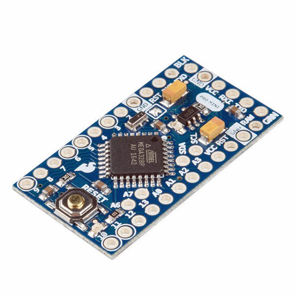
SparkFun SparkFun Arduino Pro Mini 328 (5 V, 16 MHz)
The Arduino Pro Mini is a microcontroller board based on the ATmega328P. It has 14 digital input/output pins (of which 6 can be used as PWM outputs), 6 analog inputs, an on-board resonator, a reset button, and holes for mounting pin headers. A six pin header can be connected to an FTDI cable or SparkFun breakout board to provide USB power and communication to the board. The Arduino Pro Mini is intended for semi-permanent installation in objects or exhibitions. The board comes without pre-mounted headers, allowing the use of various types of connectors or direct soldering of wires. The pin layout is compatible with the Arduino Mini. The Arduino Pro Mini was designed and is manufactured by SparkFun Electronics. Specifications Microcontroller ATmega328P Board Power Supply 5-12 V Circuit Operating Voltage 5 V Digital I/O Pins 14 PWM Pins 6 UART 1 SPI 1 I²C 1 Analog Input Pins 6 External Interrupts 2 DC Current per I/O Pin 40 mA Flash Memory 32 KB of which 2 KB used by bootloader SRAM 2 KB EEPROM 1 KB Clock Speed 16 MHz Dimensions 18 x 33.3 mm (0.7 x 1.3") Downloads Eagle files Schematics
€ 14,95€ 7,95
Best Price
-
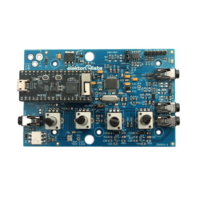
Elektor Labs Elektor Audio DSP FX Processor (New Revision)
The Elektor Audio DSP FX Processor combines an ESP32 microcontroller and an ADAU1701 Audio DSP from Analog Devices. Besides a user-programmable DSP core, the ADAU1701 has high-quality analog-to-digital and digital-to-analog converters built-in and features an I²S port. This makes it suitable as a high-quality audio interface for the ESP32. Programs for the ESP32 can be created with Arduino, Platform IO, CMake or by using the Espressif IDF in another way. Programs for the ADAU7101 audio DSPs are created with the free visual programming tool SigmaStudio by dragging and dropping pre-defined algorithm blocks on a canvas. Applications Bluetooth/Wi-Fi audio sink (e.g. loudspeaker) & source Guitar effect pedal (stomp box) Music synthesizer Sound/function generator Programmable cross-over filter for loudspeakers Advanced audio effects processor (reverb, chorus, pitch shifting, etc.) Internet-connected audio device DSP experimentation platform Wireless MIDI MIDI to CV converter and many more... Specifications ADAU1701 28-/56-bit, 50-MIPS digital audio processor supporting sampling rates of up to 192 kHz ESP32 32-bit dual-core microcontroller with Wi-Fi 802.11b/g/n and Bluetooth 4.2 BR/EDR and BLE 2x 24-bit audio inputs (2 V RMS, 20 kΩ) 4x 24-bit audio outputs (0.9 V RMS, 600 Ω) 4x Control potentiometer MIDI in- and output I²C expansion port Multi-mode operation Power supply: 5 V DC USB or 7.5-12 V DC (barrel jack, center pin is GND) Current consumption (average): 200 mA Included 1x ESP32 Audio DSP FX Processor board (assembled) 1x ESP32-PICO-KIT 2x Jumpers 2x 18-pin headers (female) 4x 10 KB potentiometers Downloads Documentation GitHub
€ 99,95€ 84,95
Best Price
-
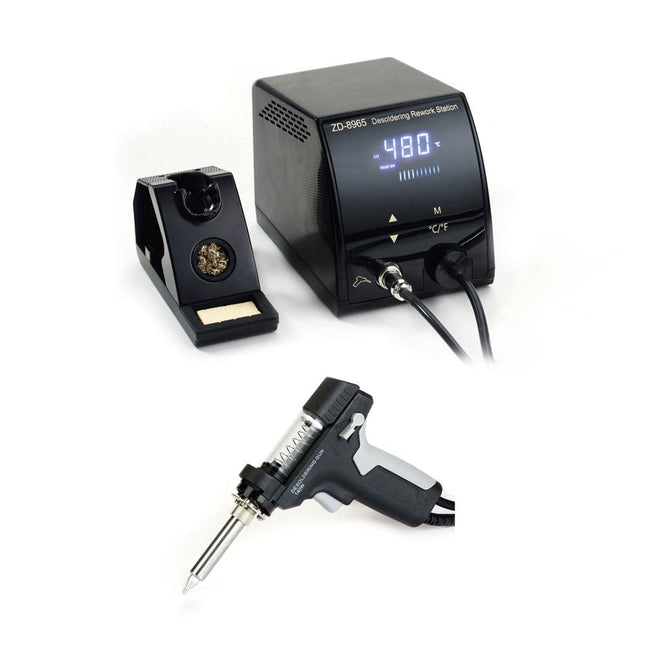
Zhongdi ZD-8965 Desoldering Station
The ZD-8965 is a digital temperature-controlled desoldering station equipped with ground protection and an LCD screen for temperature display. Despite its compact and robust design, this high-power desoldering station is easy to operate with just one hand. The ZD-8965 features a soldering gun with an integrated filter that captures any extracted material, allowing for continuous operation by simply replacing the filters. Additionally, a temperature sensor is embedded in the tip, enabling rapid response to temperature fluctuations for consistent performance. Features Effortlessly adjust the temperature between 160°C and 480°C using the convenient up/down buttons on the front panel. LED display to indicate the temperature in °C/°F Features an ergonomic pistol grip with a trigger for quick and efficient solder waste removal. The upgraded soldering gun includes a rear trigger, making it exceptionally convenient for replacing and cleaning components. Comes with a high-quality soldering gun and a sturdy holder. Equipped with a heavy-duty heater that ensures optimal desoldering performance every time. Specifications Station Voltage supply 220-240 V Power 140 W Vakuum pressure 600 mm HG Desoldering Gun Power 140 W (18 V DC)Heat up rating: 140 W Temperature 160-480°C (320-896°F) Heating element Ceramic heater Included 1x ZD-8965 Desoldering station 2x Spare soldering tips 3x Cleaning needles for desoldering tips 3x Spare filter for desoldering gun 1x Spare filter for desoldering station 1x Manual
€ 99,00
-

Elektor Labs Elektor AM Transmitter Kit
Build Your Own Vintage Radio Broadcaster The Elektor AM Transmitter Kit allows streaming audio to vintage AM radio receivers. Based on a Raspberry Pi Pico microcontroller module, the AM Transmitter can transmit on 32 frequencies in the AM band, from 500 kHz up to 1.6 MHz in 32 steps of approx. 35 kHz. The frequency is selected with a potentiometer and shown on a 0.96" OLED display. A pushbutton allows toggles the transmitting mode between On and Off. The range of the transmitter depends on the antenna. The onboard antenna provides a range of a few centimeters, requiring the AM Transmitter to be placed close to or inside the radio. An external loop antenna (not included) can be connected to increase the range. The Elektor AM Transmitter Kit comes as a kit of parts that you must solder to the board yourself. Features The board is compatible with a Hammond 1593N enclosure (not included).A 5 VDC power supply with micro-USB connector (e.g., an old phone charger) is needed to power the kit (not included). Current consumption is 100 mA. The Arduino software (requiring Earle Philhower’s RP2040 Boards Package) for the Elektor AM Transmitter Kit plus more information is available at the Elektor Labs page of this project. Component List Resistors R1, R4 = 100 Ω R2, R3, R8 = 10 kΩ R5, R6, R9, R10, R11 = 1 kΩ R7 = optional (not included) P1 = potentiometer 100 kΩ, linear Capacitors C1 = 22 µF 16V C2, C4 = 10 nF C3 = 150 pF Miscellaneous K1 = 4×1 pin socket K2, K3 = 3.5 mm socket Raspberry Pi Pico pushbutton, angle mount 0.96" monochrome I²C OLED display PCB 150292-1
€ 34,95€ 29,95
Best Price
-

Elektor Publishing Mastering FPGA Chip Design
For Speed, Area, Power, and Reliability This book teaches the fundamentals of FPGA operation, covering basic CMOS transistor theory to designing digital FPGA chips using LUTs, flip-flops, and embedded memories. Ideal for electrical engineers aiming to design large digital chips using FPGA technology. Discover: The inner workings of FPGA architecture and functionality. Hardware Description Languages (HDL) like Verilog and VHDL. The EDA tool flow for converting HDL source into a functional FPGA chip design. Insider tips for reliable, low power, and high performance FPGA designs. Example designs include: Computer-to-FPGA UART serial communication. An open-source Sump3 logic analyzer implementation. A fully functional graphics controller. What you need: Digilent BASYS3 or similar FPGA eval board with an AMD/Xilinx FPGA. Vivado EDA tool suite (available for download from AMD website free of charge). Project source files available from author’s GitHub site.
€ 39,95
Members: € 35,96
-
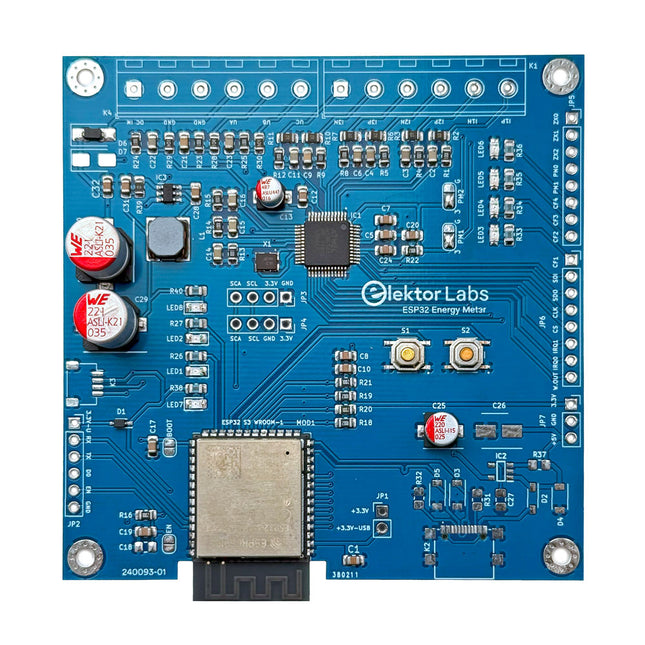
Elektor Labs Elektor ESP32 Energy Meter
The Elektor ESP32 Energy Meter is a device designed for real-time energy monitoring and smart home integration. Powered by the ESP32-S3 microcontroller, it offers robust performance with modular and scalable features. The device uses a 110/230 VAC to 12 VAC step-down transformer for voltage sampling, ensuring galvanic isolation and safety. Its compact PCB layout includes screw-type terminal blocks for secure connections, a Qwiic connector for additional sensors, and a programming header for direct ESP32-S3 configuration. The energy meter is compatible with single-phase and three-phase systems, making it adaptable for various applications. The energy meter is simple to set up and integrates with Home Assistant, offering real-time monitoring, historical analytics, and automation capabilities. It provides accurate measurements of voltage, current, and power, making it a valuable tool for energy management in homes and businesses. Features Comprehensive Energy Monitoring: Get detailed insights into your energy usage for smarter management and cost savings. Customizable Software: Tailor functionality to your needs by programming and integrating custom sensors. Smart Home Ready: Compatible with ESPHome, Home Assistant, and MQTT for full Smart Home integration. Safe & Flexible Design: Operates with a 110/230 VAC to 12 VAC step-down transformer and features a pre-assembled SMD board. Quick Start: Includes one Current Transformer (CT) sensor and access to free setup resources. Specifications Microcontroller ESP32-S3-WROOM-1-N8R2 Energy Metering IC ATM90E32AS Status Indicators 4x LEDs for power consumption indication2x Programmable LEDs for custom status notifications User Input 2x Push buttons for user control Display Output I²C OLED display for real-time power consumption visualization Input Voltage 12~16 VAC (via a step-down transformer 110/230 VAC to 12 VAC) Clamp Current Sensor YHDC SCT013-000 (100 A/50 mA) included Smart Home Integration ESPHome, Home Assistant, and MQTT for seamless connectivity Connectivity Header for programming, Qwiic for sensor expansion Applications Supports single-phase and three-phase energy monitoring systems Dimensions 79.5 x 79.5 mm Included 1x Partly assembled board (SMDs are pre-mounted) 2x Screw terminal block connectors (not mounted) 1x YHDC SCT013-000 current transformer Required Power transformer not included Downloads Datasheet (ESP32-S3-WROOM-1) Datasheet (ATM90E32AS) Datasheet (SCT013-000) Frequently Asked Questions (FAQ) From Prototype to Finished Product What started as an innovative project to create a reliable and user-friendly energy meter using the ESP32-S3 microcontroller has evolved into a robust product. Initially developed as an open-source project, the ESP32 Energy Meter aimed to provide precise energy monitoring, smart home integration and more. Through meticulous hardware and firmware development, the energy meter now stands as a compact, versatile solution for energy management.
€ 79,95€ 64,95
Best Price
-

Elektor Publishing Coding Modbus TCP/IP for Arduino
Example projects with Node-RED, MQTT, WinCC SCADA, Blynk, and ThingSpeak This comprehensive guide unlocks the power of Modbus TCP/IP communication with Arduino. From the basics of the Modbus protocol right up to full implementation in Arduino projects, the book walks you through the complete process with lucid explanations and practical examples. Learn how to set up Modbus TCP/IP communication with Arduino for seamless data exchange between devices over a network. Explore different Modbus functions and master reading and writing registers to control your devices remotely. Create Modbus client and server applications to integrate into your Arduino projects, boosting their connectivity and automation level. With detailed code snippets and illustrations, this guide is perfect for beginners and experienced Arduino enthusiasts alike. Whether you‘re a hobbyist looking to expand your skills or a professional seeking to implement Modbus TCP/IP communication in your projects, this book provides all the knowledge you need to harness the full potential of Modbus with Arduino. Projects covered in the book: TCP/IP communication between two Arduino Uno boards Modbus TCP/IP communication within the Node-RED environment Combining Arduino, Node-RED, and Blynk IoT cloud Interfacing Modbus TCP/IP with WinCC SCADA to control sensors Using MQTT protocol with Ethernet/ESP8266 Connecting to ThingSpeak IoT cloud using Ethernet/ESP8266
€ 39,95
Best Price
-
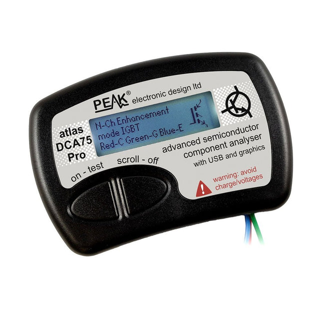
Peak Peak Atlas DCA75 Pro (Advanced Semiconductor Analyzer)
The DCA75 Pro is a great instrument that combines ease-of-use with amazing features. It can automatically identify a huge range of semiconductors, automatically identify pinouts and measure detailed parameters. Features Built-in graphics display (now backlit) to show detailed schematic of the component you're testing as well as pinout and measurement data USB connectivity to allow curve tracing, data storage/retrieval and device matching on your Windows PC (Windows 7 and higher) Single internal AAA alkaline cell for standalone operation Component Support Bipolar transistors (NPN/PNP inc Silicon/Germanium) Darlington transistors (NPN/PNP) Enhancement mode MOSFETs (N-Ch and P-Ch) Depletion mode MOSFETs (N-Ch and P-Ch) Junction FETs (N-Ch and P-Ch). Both symmetrical and asymmetrical types Enhancement IGBTs (N-Ch and P-Ch) Diodes and diode networks (2 and 3 lead types) Zener diodes (up to about 9 V) Voltage regulators (up to about 8 V) LEDs and bi-colour LEDs (2 lead and 3 lead types) Low power sensitive Triacs and Thyristors (<10 mA trigger and hold) Measurements BJT current gain (hFE) BJT base emitter voltage (Vbe) BJT collector leakage current MOSFET on and off gate threshold voltages MOSFET transconductance JFET pinch-off voltage JFET transconductance JFET IDSS (drain current for Vgs=0) IGBT on and off gate threshold voltages IGBT transconductance Voltage regulator output voltage Voltage regulator quiescent current consumption Voltage regulator drop-out voltage Zener voltage Diode forward voltage drop Specifications Analyzer type Semiconductor components Component detection Automatic Pinout detection Automatic, connect any way round Display type Graphic LCD (now backlit) Interface type USB for optional PC connection PC functions Curve tracing (Windows 7 and higher) Software Included on USB drive for Windows 7 and higher Battery Single AAA cell (supplied) Included Peak Atlas DCA75 Pro PC software on a USB Flash Drive for Windows 11, 10, 8, 7, XP Micro USB cable Fitted universal premium hook probes AAA Alkaline battery Downloads Datasheet (EN) User Guide (EN) User Guide (IT) Software Installation Guide (EN) Software and Firmware Package
€ 192,39
-

Elektor Publishing Arduino for Radio Amateur Applications
Program and build Arduino-based ham station utilities, tools, and instruments In addition to a detailed introduction to the exciting world of the Arduino microcontroller and its many variants, this book introduces you to the shields, modules, and components you can connect to the Arduino. Many of these components are discussed in detail and used in the projects included in this book to help you understand how these components can be incorporated into your own Arduino projects. Emphasis has been placed on designing and creating a wide range of amateur radio-related projects that can easily be built in just a few days. This book is written for ham radio operators and Arduino enthusiasts of all skill levels, and includes discussions about the tools, construction methods, and troubleshooting techniques used in creating amateur radio-related Arduino projects. The book teaches you how to create feature-rich Arduino-based projects, with the goal of helping you to advance beyond this book, and design and build your own ham radio Arduino projects. In addition, this book describes in detail the design, construction, programming, and operation of the following projects: CW Beacon and Foxhunt Keyer Mini Weather Station RF Probe with LED Bar Graph DTMF Tone Encoder DTMF Tone Decoder Waveform Generator Auto Power On/Off Bluetooth CW Keyer Station Power Monitor AC Current Monitor This book assumes a basic knowledge of electronics and circuit construction. Basic knowledge of how to program the Arduino using its IDE will also be beneficial.
€ 39,95
Members: € 35,96


