EASTER SALE: Order the Geekworm KVM-A3 Kit now and receive the e-book Raspberry Pi Full Stack (worth €35) for FREE!
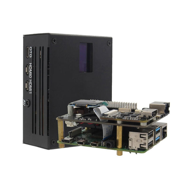
KVM stands for Keyboard, Video, and Mouse and it is a powerful open-source software that enables remote access via Raspberry Pi. This KVM-A3 kit is designed based on the Raspberry Pi 4.
With it, you can turn your computer on or off, restart it, configure the UEFI/BIOS, and even reinstall the operating system using a virtual CD-ROM or flash drive. You can either use your own remote keyboard and mouse, or let KVM simulate a keyboard, mouse, and monitor – presented through a web browser as if you were directly interacting with the remote system. It's true hardware-level access with no dependency on remote ports, protocols, or services!
Features
Designed especially for KVM (an open and affordable DIY IP-KVM based on Raspberry Pi)
Compatible with Raspberry Pi 4 (not included)
Fully compatible with PiKVM V3 OS
Control a server or computer using a web browser
HDMI Full HD capture based on the TC358743 chip
OTG keyboard and mouse support; mass storage drive emulation
Hardware Real-Time Clock (RTC) with CR1220 coin battery socket
Equipped with a cooling fan to dissipate heat from the Raspberry Pi
Features solid-state relays to protect Raspberry Pi GPIO pins from computer and ESD spikes
ATX control via RJ45 connector: switch the machine on or off, reset it, and monitor HDD and power LED status remotely
10-pin SH1.0 connector reserved for future I²S HDMI audio support
4-pin header and spacers reserved for I²C OLED display
Included
KVM-A3 Metal Case for Raspberry Pi 4
X630 HDMI to CSI-2 Module (for video capture)
X630-A3 Expansion Board (provides Ethernet, cooling, RTC, power input, etc.)
X630-A5 Adapter Board (installed inside the PC case; connects the computer motherboard to the IO panel cable of the PC case)
0.96-inch OLED Display (128 x 64 pixels)
Ethernet Cable (TIA/EIA-568.B standard; also serves as the ATX control signal cable)
Downloads
Wiki
PiKVM OS
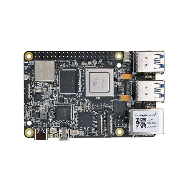
BeagleY-AI is a low-cost, open-source, and powerful 64-bit quad-core single-board computer, equipped with a GPU, DSP, and vision/deep learning accelerators, designed for developers and makers.
Users can take advantage of BeagleBoard.org's provided Debian Linux software images, which include a built-in development environment. This enables the seamless running of AI applications on a dedicated 4 TOPS co-processor, while simultaneously handling real-time I/O tasks with an 800 MHz microcontroller.
BeagleY-AI is designed to meet the needs of both professional developers and educational environments. It is affordable, easy to use, and open-source, removing barriers to innovation. Developers can explore in-depth lessons or push practical applications to their limits without restriction.
Specifications
Processor
TI AM67 with quad-core 64-bit Arm Cortex-A53, GPU, DSP, and vision/deep learning accelerators
RAM
4 GB LPDDR4
Wi-Fi
BeagleBoard BM3301 module based on TI CC3301 (802.11ax Wi-Fi)
Bluetooth
Bluetooth Low Energy 5.4 (BLE)
USB
• 4x USB-A 3.0 supporting simultaneous 5 Gbps operation• 1x USB-C 2.0 supports USB 2.0 device
Ethernet
Gigabit Ethernet, with PoE+ support (requires separate PoE+ HAT)
Camera/Display
1x 4-lane MIPI camera/display transceivers, 1x 4-lane MIPI camera
Display Output
1x HDMI display, 1x OLDI display
Real-time Clock (RTC)
Supports an external button battery for power failure time retention. It is only populated on EVT samples.
Debug UART
1x 3-pin debug UART
Power
5 V/5 A DC power via USB-C, with Power Delivery support
Power Button
On/Off included
PCIe Interface
PCI-Express Gen3 x1 interface for fast peripherals (requires separate M.2 HAT or other adapter)
Expansion Connector
40-pin header
Fan connector
1x 4-pin fan connector, supports PWM speed control and speed measurement
Storage
microSD card slot, with support for high-speed SDR104 mode
Tag Connect
1x JTAG, 1x Tag Connect for PMIC NVM Programming
Downloads
Pinout
Documentation
Quick start
Software
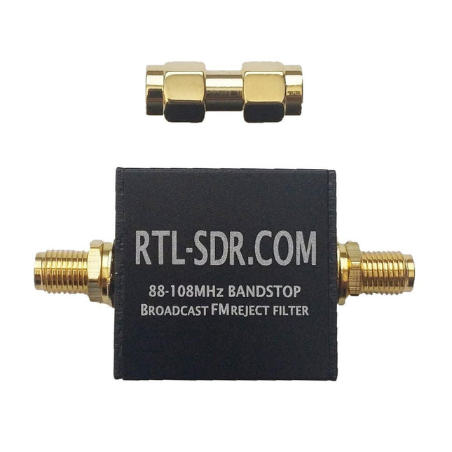
This filter rejects signals between 88-108 MHz with around 50 dB or more attenuation. A broadcast FM band-stop filter is very useful for use with SDRs as in some areas broadcast FM signals can be so strong that they overload the SDR, causing very poor performance in other bands. You can tell if this is the case for you if you see images of BCFM stations or interference that looks like a WFM signal at other frequencies when you turn up the gain.
The filter is based on a simple 7th order Chebyshev design. The 3 dB roll off is at 76 MHz and 122 MHz. 88 MHz is attenuated by almost 60 dB, and 108 MHz is attenuated by 45-50 dB. Outside of the pass band the insertion loss is practically zero below 500 MHz, less than 0.5 dB from 500 MHz – 1 GHz, and below 1.5 dB between 1-2 GHz. Between 2-3 GHz performance degrades slightly, but insertion loss remains below 1.5 dB for most frequencies. The filter can also pass up to 80 mA of DC current (probably can do more) and has negligible DC resistance.
The filter comes in a 28 x 28 x 13 mm aluminum enclosure and uses female SMA connectors on each end. Included in the package is also a SMA male to SMA male straight barrel adapter.
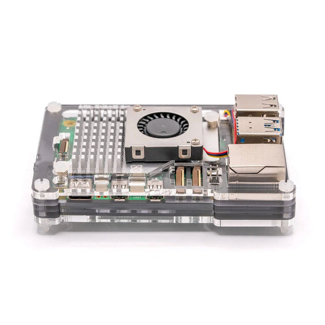
The slim, hackable and attractive case for Raspberry Pi 5.
Pibow 5 lets you access all the ports and connectors on your Raspberry Pi and even has a clever little tab that will let you push the Pi 5's brand new power button whilst it's safely ensconced in its case. The case is designed to fit neatly around Raspberry Pi's Active Cooler.
Features
Compatible with Raspberry Pi 5 Official Active Cooler
Super-slimline profile
Fully HAT/pHAT compatible
Protects your Raspberry Pi 5
Clear top leaves Raspberry Pi 5 visible (so you can gaze upon its wonder).
GPIO cut-out
Leaves all ports and connectors accessible
External Power Button Nubbin via compliant mechanism magic
Mounting holes on the base that will accommodate M2.5 screws/bolts and the studs on popular Danish ABS construction blocks
Made from lightweight high-quality cast acrylic
Great for hacking and tinkering
Crafted out of five unique layers including a transparent top that leaves your Raspberry Pi visible inside. Each layer is laser-cut from colourful high-quality cast acrylic and once stacked they securely contain a Raspberry Pi 5 while leaving the primary ports and GPIO accessible.
This case is lightweight and ideal for mounting to any surface. No tools are required for assembly or disassembly!
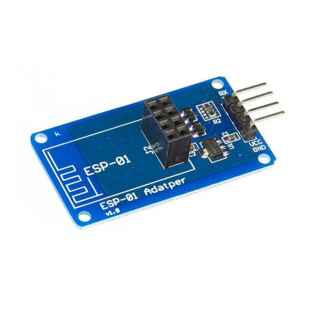
The ESP-01 Adapter 3.3-5 V is the ideal solution for connecting an ESP-01 ESP8266 module to a 5 V system such as Arduino Uno.
Features
Adapter module for ESP-01 Wi-Fi module
3.3 V voltage regulator circuit & onboard level conversion for easy use of 5 V microcontroller with ESP-01 Wi-Fi module
Compatible with Uno R3
4.5~5.5 V (on-board 3.3 V LDO Regulator)
Interface logic voltage: 3.3-5 V compatible (on-board level shift)
Current: 0-240 mA
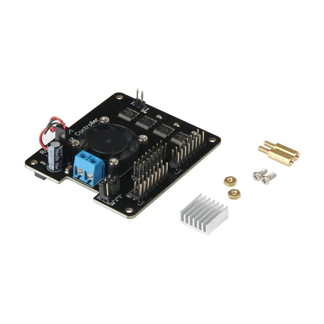
FUNCTION Logic level converter from 3.3 V to 5V for controlling of up to 3 LED matrix rows PASSIVE AND ACTIVE COOLING Aluminium heatsink with a 25x25mm sized fan COMPATIBLE WITH Raspberry Pi 3A/B/A+/B+, 4B INPUT VOLTAGE 5 Volt INTERFACES 3x HUB75 plugs DATA LINE E SWITCHABLE with jumpers to Pin 4 or 8 DIMENSIONS 65 x 56 x 26 mm WEIGHT 40 g ITEMS SHIPPED Controller, heatsink, fan, 2 spacers, 6 screws and nuts, 4 flat washers, 2 jumpers EAN 4250236819631 ARTICLE NO. RB-MatrixCtrl
RF circuit design is now more important than ever as we find ourselves in an increasingly wireless world. Radio is the backbone of today’s wireless industry with protocols such as Bluetooth, Wi-Fi, WiMax, and ZigBee. Most, if not all, mobile devices have an RF component and this book tells the reader how to design and integrate that component in a very practical fashion. This book has been updated to include today's integrated circuit (IC) and system-level design issues as well as keeping its classic ‘wire lead’ material.
Design Concepts and Tools Include
The Basics: Wires, Resistors, Capacitors, Inductors
Resonant Circuits: Resonance, Insertion Loss
Filter Design: High-pass, Bandpass, Band-rejection
Impedance Matching: The L Network, Smith Charts, Software Design Tools
Transistors: Materials, Y Parameters, S Parameters
Small Signal RF Amplifier: Transistor Biasing, Y Parameters, S Parameters
RF Power Amplifiers: Automatic Shutdown Circuitry, Broadband Transformers, Practical Winding Hints
RF Front-End: Architectures, Software-Defined Radios, ADC’s Effects
RF Design Tools: Languages, Flow, Modeling
This Electronic Component Storage Box with 128 compartments is an essential tool for anyone handling small electronic components, particularly SMDs. It provides a practical, well-organized solution for storing a wide array of miniature parts like resistors, capacitors, diodes, and transistors. Each component can be stored in its own dedicated space, ensuring that the specific part you need for any project is always easy to locate.
Whether you're a professional electronics engineer, a maker or a DIY enthusiast, this storage box offers the perfect blend of functionality and convenience. Its design helps eliminate clutter, optimize component management and keep your work environment tidy so you can focus on what really matters: building and troubleshooting electronic circuits.
Dimensions of each compartment (L x W x H): 22 x 15 x 16 mm
Dimensions of the box (L x W x H): 280 x 215 x 45 mm
Included
1x Component Storage Box (incl. 128 compartments with lids and foam)
3x Spare lids
2x Sheets of blank labels
2x Box labels
Specifications Material: Conductive fastener tape: nylon Interior surface: conductive carbon Grounding cord: PU coil cord with resistor of 1 Mohm Band size: 2 x 23 cm Band resistivity: < 50 Ohm Color: blue
Create lightning with the touch of your fingers or the clap of your hands
The Plasma Magic Ball is a cutting-edge tech gadget and an eye-catching piece of art. Inside the glass sphere, a special gas mixture creates mesmerizing light effects when activated by high-frequency current – like holding a storm in your hands.
Perfect for use at home, in the office, schools, hotels, or bars, it’s a unique decorative element that sparks curiosity. Looking for a fun and unusual gift? The Plasma Magic Ball is a great choice for friends and family alike.
Despite its stunning effects, the Plasma Magic Ball uses very little electricity. The glass itself is made of specially hardened, high-strength material and can withstand temperatures of up to 522°C (972°F).
Specifications
Material
Plastic
Ball diameter
6 inch (15 cm)
Input voltage
220 V
Output voltage
12 V
Power
15 W
Dimensions
25 x 15.5 x 15.5 cm
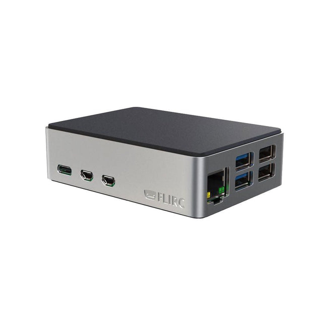
Discover the perfect case for your Raspberry Pi 5. FLIRC has made the power button accessible and improved it with LED support. Enjoy the familiar aluminium core heatsink you've come to love, nestled between two matte black soft-touch panels. Customised to fit into your entertainment system. Built-in Heat Sink This is the first affordable Raspberry Pi case made from aluminium. FLIRC wanted to ensure that form didn't take precedence over function, so they used the aluminium body of the case as a built-in heat sink. Included with the case is a thermal pad and 4 screws for easy assembly. Stability and Access FLIRC has built in rubber feet to elevate the case so that it simply floats under your TV. In addition to the built-in heatsink, small ventilation slots on the bottom ensure that the Raspberry Pi stays cool. The GPIO pins are accessible via the slot at the bottom of the case, and the SD card does not need to be disassembled to reach them. Power Button and LED Support The power button of the Raspberry Pi 5 is natively supported by the FLIRC housing. The activity LEDs are also clearly visible.
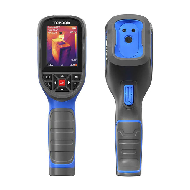
The TOPDON TC004 SE is a reliable thermal camera designed for locating and tackling industrial, electrical, building, HVAC, and automotive problems with confidence. With an impressive battery life of up to 21 hours (at low brightness), it ensures all-day use. Its video recording capability allows you to monitor maintenance history and reassure customers that systems are functioning safely.
The TC004 SE enhances your diagnostic capabilities, excelling in pinpointing and resolving issues across multiple industries, including industrial, electrical, building, HVAC, and automotive.
Features
21-hour runtime for reliable all-day use (at low brightness)
Supports video recording for later review
Store up to 160,000 images with built-in 32 GB storage
Professional PC software for expanded display and thermal data analysis
Switch between 1x, 2x, and 4x digital zoom to capture every detail
Detailed & smooth images with 256 x 192 IR resolution and 25 Hz refresh rate
Mount on a tripod for steady monitoring
Two built-in LED lights for inspecting hard-to-reach areas
Specifications
TC004
TC004 SE
TC004 Lite
Display
2.8" Color TFT (320 x 240 Pixels)
2.8" Color TFT (320 x 240 Pixels)
2.8" Color TFT (320 x 240 Pixels)
IR light resolution
256 x 192 Pixels
256 x 192 Pixels
160 x 120 Pixels
Spectral range
8~14 μm
8~14 μm
8~14 μm
FOV
52.5° x 39.5°
56° x 42°
40° x 30°
Storage
2 GB RAM + 16 GB TF card
32 GB Built-in
512 MB Built-in
Measuring range
−20~350°C (−4~662°F)
−20~550°C (−4~1022°F)
−20~550°C (−4~1022°F)
Temperature resolution
0.1°C (0.18°F)
0.1°C (0.18°F)
0.1°C (0.18°F)
Measuring modes
Center spot/hot spot/cold spot
Center spot/hot spot/cold spot
Center spot/hot spot/cold spot
Measuring accuracy
±2°C or ±2%
±2°C or ±2%
±2°C or ±2%
Frame rate
25 Hz
25 Hz
25 Hz
Focal length
3.2 mm (0.12")
3.2 mm (0.12")
2.6 mm (0.1")
NETD
<40 mK
<40 mK
<40 mK
Magnification
1x/2x/4x (digital zoom)
1x/2x/4x (digital zoom)
1x/2x/4x (digital zoom)
Tripod screw hole
Yes
Yes
Yes
High/Low temperature alarm
Yes
Yes
Yes
LED flashlight
Yes
Yes
No
Video recording
Yes
Yes
No
Auto shutdown
5 min, 10 min, 20 min, OFF
5 min, 10 min, 20 min, OFF
5 min, 10 min, 20 min, OFF
Battery
Built-in 5000 mAh battery
Built-in 5300 mAh battery
Built-in 2900 mAh battery
Charging time
4 h
4 h
4 h
Standby time
12 h
16 h (High Brightness)21 h (Low Brightness)
15 h
Operating system
Standalone use/Windows devices
Standalone use/Windows devices
Standalone use
PC-based analysis
Supports image analysis with PC
Yes
No
Dimensions
240 x 70 x 90 mm
240 x 70 x 90 mm
240 x 70 x 90 mm
Weight
520 g
520 g
520 g
Included
1x TOPDON TC004 SE Thermal Imaging Camera
1x USB Power Supply
4x Plugs (EU, UK, US, and AU)
1x USB Cable
1x Storage Bag
1x Manual
Downloads
Manual
PC Software (Windows)
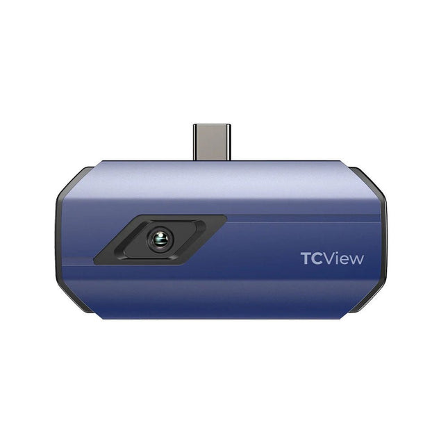
The TC001 is a portable camera that transforms your Android smartphone/tablet or Windows laptop into a powerful thermal imager. Simply download the accompanying app, connect the TC001 to your device’s USB-C port, and access thermal technology once exclusive to specialists.
Ideal for home inspectors, HVAC technicians, electricians, automotive technicians, and even farmers seeking to protect crops and livestock, the TC001 is perfect for professionals across various fields.
Specifications
Resolution
256 x 192 pixels
Pixel Size
12 μm
Spectral Range
8~14 μm
Focal Length
3.2 mm
Temperature Range
−20°C to 550°C (−4°F to 1022°F)
Temperature Accuracy
±2°C or ±2%
Temperature Resolution
0.1°C
Frame Rate
25 Hz
NETD
<40 mK
Field of View
56° x 42°
Color Palettes
10 Colors
High/Low Temperature Alarm
Yes
Compatible Systems
Android/Windows Devices with USB-C
Dimensions
71 x 42 x 14 mm
Weight
30 g
Included
TC001 Thermal Imaging Camera
Multifunctional Adapter Cable (50 cm)
Carrying Bag
Cleaning Cloth
Manual
Downloads
Manual
Datasheet
Android App
Windows App
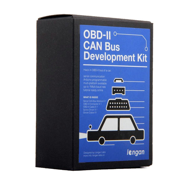
This kit is the perfect solution for you to communicate with your vehicle's OBD-II interface without visiting a mechanic. It includes a Serial CAN Bus module, an OBD-II Connector, and other accessories to help you do all the diagnostics and data logging with ease. There is also a tutorial which is based on Arduino and you can easily obtain data from your vehicle by following this tutorial.
Features
Fast serial communication with CAN Bus rate up to 1 MB/s
Easy Setup with all components included
Easily get started with the provided Arduino-based tutorials
Multi-platform support (Arduino, Raspberry Pi, Beaglebone Board, etc.)
Included
1x Serial CAN Bus Module
1x OBD-II Connector
1x Screwdriver
1x Cable for CAN Bus
1x Grove Cable
Downloads
Wiki
Arduino Library
Schematics
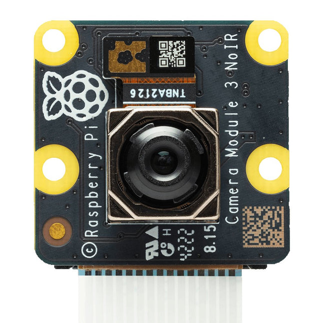
Raspberry Pi Camera Module 3 is a compact camera from Raspberry Pi. It offers an IMX708 12-megapixel sensor with HDR, and features phase detection autofocus. Camera Module 3 is available in standard and wide-angle variants, both of which are available with or without an infrared cut filter.
Camera Module 3 can be used to take full HD video as well as stills photographs, and features an HDR mode up to 3 megapixels. Its operation is fully supported by the libcamera library, including Camera Module 3’s rapid autofocus feature: this makes it easy for beginners to use, while offering plenty for advanced users. Camera Module 3 is compatible with all Raspberry Pi computers.
All variants of Raspberry Pi Camera Module 3 feature:
Back-illuminated and stacked CMOS 12-megapixel image sensor (Sony IMX708)
High signal-to-noise ratio (SNR)
Built-in 2D Dynamic Defect Pixel Correction (DPC)
Phase Detection Autofocus (PDAF) for rapid autofocus
QBC Re-mosaic function
HDR mode (up to 3 megapixel output)
CSI-2 serial data output
2-wire serial communication (supports I²C fast mode and fast-mode plus)
2-wire serial control of focus mechanism
Specifications
Sensor
Sony IMX708
Resolution
11.9 MP
Sensor size
7.4 mm sensor diagonal
Pixel size
1.4 x 1.4 µm
Horizontal/vertical
4608 x 2592 pixels
Common video modes
1080p50, 720p100, 480p120
Output
RAW10
IR cut filter
Integrated in standard variants; not present in NoIR variants
Autofocus system
Phase Detection Autofocus
Ribbon cable length
200 mm
Cable connector
15 x 1 mm FPC
Dimensions
25 x 24 x 11.5 mm (12.4 mm height for Wide variants)
Variants of Raspberry Pi Camera Module 3
Camera Module 3
Camera Module 3 NoIR
Camera Module 3 Wide
Camera Module 3 Wide NoIR
Focus range
10 cm - ∞
10 cm - ∞
5 cm - ∞
5 cm - ∞
Focal length
4.74 mm
4.74 mm
2.75 mm
2.75 mm
Diagonal field of view
75 degrees
75 degrees
120 degrees
120 degrees
Horizontal field of view
66 degrees
66 degrees
102 degrees
102 degrees
Vertical field of view
41 degrees
41 degrees
67 degrees
67 degrees
Focal ratio (F-stop)
F1.8
F1.8
F2.2
F2.2
Infrared-sensitive
No
Yes
No
Yes
Downloads
GitHub
Documentation
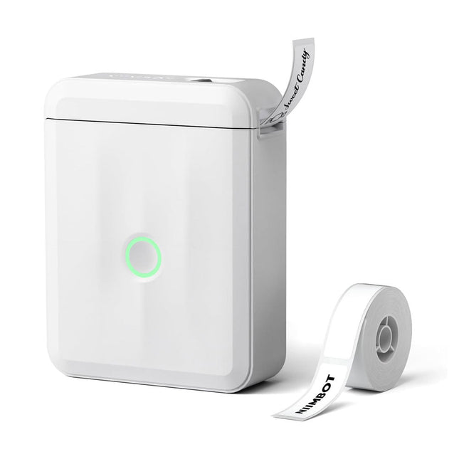
Based on direct thermal technology, the Niimbot D110 label printer offers a printing experience without ink, toner or ribbons, making it a cost-effective solution compared to traditional printers. Its compact size and light weight make it easy to transport and fits easily into any pocket.
With Bluetooth connectivity and a built-in 1500 mAh battery, this wireless mini printer allows you to print from up to 10 meters away, giving you flexibility on the go, whether you're printing from your smartphone or tablet.
The "Niimbot" app (available for iOS and Android) offers a variety of free templates for customizing labels.
Specifications
Model
D110_M (Upgraded Version 2024)
Material
ABS
Resolution
203 DPI
Printing speed
30-60 mm/s
Print width
12-15 mm
Printing technology
Thermal
Operating temperature
5°C ~ 45°C (41°F ~ 113°F)
Battery capacity
1500 mAh
Charging interface
USB-C
Charging time
2 hours
Connection
Bluetooth 4.0
Wireless distance
10 m
Dimensions
98 x 76 x 30 mm
Weight
149 g
Included
1x Niimbot D110 Label Printer
1x Label tape (12 x 40 mm)
1x USB cable
1x Manual
Downloads
iOS App
Android App
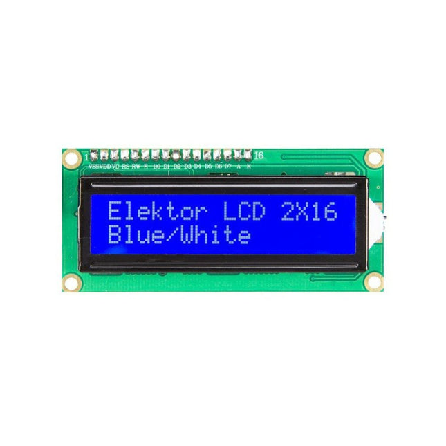
2x16 Character LCD Module (blue/white)
Pin No. Pin Name Descriptions 1 VSS Ground 2 VDD Supply voltage for logic 3 V0 Input voltage for LCD 4 RS Data / Instruction Regster Select (H : Data signal, L : Instruction signal) 5 R/W Read / Write (H : Read mode, L : Write mode) 6 E Enable signal 7 DB0 Data bit 0 8 DB1 Data bit 1 9 DB2 Data bit 2 10 DB3 Data bit 3 11 DB4 Data bit 4 12 DB5 Data bit 5 13 DB6 Data bit 6 14 DB7 Data bit 7 15 LED_A Backlight Anode 16 LED_K Backlight Cathode
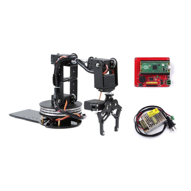
Raspberry Pi Pico is a great solution for servo control. With the hardware PIO, the Pico can control the servos by hardware, without usage of times/ interrupts, and limit the usage of the MCU. Driving the six servos on this robotic arm takes very little MCU capacity, so the MCU can deal with other tasks easily. This 6 DOF robotic arm is a handy tool for teaching and learning robotics and Pico usage. There are five MG996s (four are needed in the assembly and one for backup) and three 25-kg servos (two needed in the assembly and one for backup). Note that for the servos the angle ranges from 0° to 180°. All the servos need to be preset to 90° (with logic HIGH 1.5 ms duty) before the assembly to avoid servo damage during movement. This product includes all the necessary items needed to create a robotic arm based on Pico and Micropython. Included 1x Raspberry Pi Pico 1x Raspberry Pi Pico Servo Driver 1x Set '6 DOF Robot Arm' 1x 5 V/5 A Power Supply 2x Backup Servo Downloads GitHub Wiki Assembly Guide Assembly Video
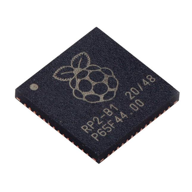
Technical Specifications Dual ARM Cortex-M0+ @ 133 MHz 264 kB on-chip SRAM in six independent banks Support for up to 16 MB of off-chip Flash memory via dedicated QSPI bus DMA controller Fully-connected AHB crossbar Interpolator and integer divider peripherals On-chip programmable LDO to generate core voltage 2x on-chip PLLs to generate USB and core clocks 30x GPIO pins, 4 of which can be used as analogue inputs Peripherals 2x UARTs 2x SPI controllers 2x I²C controllers 16x PWM channels USB 1.1 controller and PHY, with host and device support 8x PIO state machines What you'll get 10x bare RP2040 chips
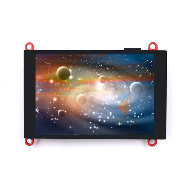
The ESP32-S3 Parallel TFT not only offers more SRAM and ROM (compared to the S2 version), but with Bluetooth 5.0 it is also suitable for applications such as local monitoring and controlling.
The built-in LCD driver ILI9488 uses 16-bit parallel lines to communicate with ESP32-S3, the main clock can be up to 20 MHz, which makes the display smooth enough for video displays. With this display, you can create more IoT display projects.
Features
Controller: ESP32-S3-WROOM-1, PCB Antenna, 16 MB Flash, 2 MB PSRAM, ESP32-S3-WROOM-1-N16R2
Wireless: Wifi & Bluetooth 5.0
LCD: 3.5-inch TFT LCD
Resolution: 480x320
Color: RGB
LCD Interface: 16-bit parallel
LCD Driver: ILI9488
Touch Panel: Capacitive
Touch Panel Driver: FT6236
USB: Dual USB Type-C (one for USB-to-UART and one for native USB)
UART to UART Chip: CP2104
Power Supply: USB Type-C 5.0 V (4.0 V~5.25 V)
Button: Flash button and reset button
Mabee Interface: 1x I²C, 1x GPIO
Backlight Controller: Yes
MicroSD: Yes
Arduino support: Yes
Type-C Power Delivery: Not supported
Operation temperature: -40℃ to +85℃
Dimension: 66 x 84.3 x 12 mm
Weight: 52 g
Downloads
ESP32-S3 Datasheet
GitHub
Wiki
LVGL Demo Code
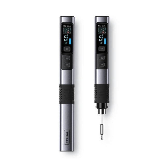
The FNIRSI HS-02A is an improved version of the HS-01 soldering iron with a better grip and a shorter tip for more comfort and precision during use. It features a larger 0.96-inch IPS HD color display that allows for better visibility of settings and status. With an output power of 100 W, the HS-02A heats up quickly and reaches operating temperature in about 2 seconds. The temperature is adjustable in a range of 100-450°C (212-842°F) to meet different soldering requirements.
Features
Temperature: 100-450°C (212-842°F)
Accurate temperature adjusting and control
Fast heating
CNC Metal Shell
Adaptive Power
100 W High Power
Protocols: PD, QC
Specifications
Temperature Range
100-450°C (212-842°F)
Working Voltage
9-20 V
Display
0.96" IPS HD Color Screen
Power Supply
USB-C
Fast Charging Protocols
PD / QC
Power
100 W (max)
Dimensions
180 x 20 mm
Weight
61 g
Included
1x FNRISI HS-02A Smart soldering iron
6x Soldering iron tips (HS02A-KU, HS02A-K, HS02A-JS, HS02A-I, HS02A-C2, HS02A-B)
1x 100 W USB-C power supply (EU)
1x DC to USB-C power cable
1x USC-C charging cable
1x Mini soldering iron stand
1x Manual
Downloads
Manual
Firmware V1.7
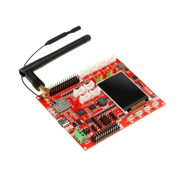
Lora technology and Lora devices have been widely used in the field of the Internet of Things (IoT), and more and more people are joining and learning Lora development, making it an indispensable part of the IoT world. To help beginners learn and develop Lora technology better, a Lora development board has been designed specifically for beginners, which uses RP2040 as the main control and is equipped with the RA-08H module that supports Lora and LoRaWAN protocols to help users realize development. RP2040 is a dual-core, high-performance, and low-power ARM Cortex-M0+ architecture chip, suitable for IoT, robots, control, embedded systems, and other application fields. RA-08H is made from the Semtech-authorized ASR6601 RF chip, which supports the 868 MHz frequency band, has a 32 MHz MCU built-in, which has more powerful functions than ordinary RF modules, and also supports AT command control. This board retains various functional interfaces for development, such as the Crowtail interface, the common PIN to PIN header that leads out GPIO ports, and provides 3.3 V and 5 V outputs, suitable for the development and use of commonly used sensors and electronic modules on the market. In addition, the board also reserves RS485 interface, SPI, I²C, and UART interfaces, which can be compatible with more sensors/modules. In addition to the basic development interfaces, the board also integrates some commonly used functions, such as a buzzer, a custom button, red-yellow-green three-color indicator lights, and a 1.8-inch SPI interface LCD screen with a resolution of 128x160. Features Uses RP2040 as the main controller, with two 32-bit ARM Cortex M0+ processor cores (dual-core), and provides more powerful performance Integrates the RA-08H module with 32 MHz MCU, supports the 868 MHz frequency band and AT command control Abundant external interface resources, compatible with Crowtail series modules and other common interface modules on the market Integrates commonly used functions like buzzer, LED light, LCD display and custom button, making it more concise and convenient when creating projects Onboard 1.8-inch 128x160 SPI-TFT-LCD, ST7735S driver chip Compatible with Arduino/Micropython, easy to carry out different projects Specifications Main Chip Raspberry Pi RP2040, built-in 264 KB SRAM, onboard 4 MB Flash Processor Dual Core Arm Cortex-M0+ @ 133 MHz RA-08H Frequency band 803-930 MHz RA-08H Interface External antenna, SMA interface or IPEX first-generation interface LCD Display Onboard 1.8-inch 128x160SPI-TFT-LCD LCD Resolution 128x160 LCD Driver ST7735S (4-wire SPI) Development environment Arduino/MicroPython Interfaces 1x passive buzzer 4x user-defined buttons 6x programmable LEDs 1x RS485 communication interface 8x 5 V Crowtail interfaces (2x analog interfaces, 2x digital interfaces, 2x UART, 2x I²C) 12x 5 V universal pin header IO 14x 3.3 V universal pin header IO 1x 3.3 V/5 V switchable SPI 1x 3.3 V/5 V switchable UART 3x 3.3 V/5 V switchable I²C Working input voltage USB 5 V/1 A Operating temperature -10°C ~ 65°C Dimensions 102 x 76.5 mm (L x W) Included 1x Lora RA-08H Development Board 1x Lora Spring Antenna (868 MHz) 1x Lora Rubber Antenna (868 Mhz) Downloads Wiki
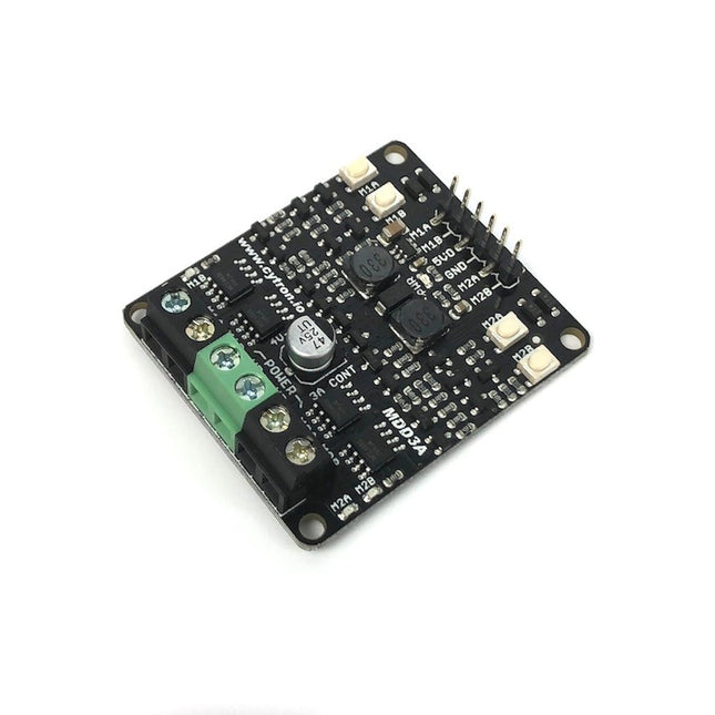
Features: Supports motor voltage from 4 V to 16 V DC Bidirectional control for two brushed DC motor. Control one unipolar or one bipolar stepper motor. Maximum Motor Current: 3A continuous, 5A peak LEDs for motor output state. Buttons for quick testing. Compatible with Arduino and Raspberry Pi PWM frequency up to 20kHz Reverse polarity protection Here you can find the product's Datasheet. Check out the sample code provided by Cytron here.