Development Boards
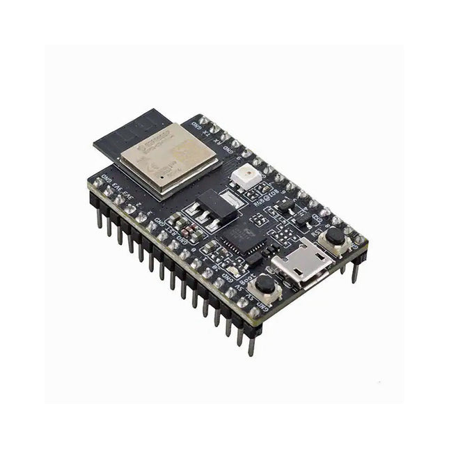
Espressif ESP32-C3-DevKitM-1
ESP32-C3-DevKitM-1 is an entry-level development board based on ESP32-C3-MINI-1, a module named for its small size. This board integrates complete Wi-Fi and Bluetooth LE functions. Most of the I/O pins on the ESP32-C3-MINI-1 module are broken out to the pin headers on both sides of this board for easy interfacing. Developers can either connect peripherals with jumper wires or mount ESP32-C3-DevKitM-1 on a breadboard. Specifications ESP32-C3-MINI-1 ESP32-C3-MINI-1 is a general-purpose Wi-Fi and Bluetooth LE combo module that comes with a PCB antenna. At the core of this module is ESP32-C3FN4, a chip that has an embedded flash of 4 MB. Since flash is packaged in the ESP32-C3FN4 chip, rather than integrated into the module, ESP32-C3-MINI-1 has a smaller package size. 5 V to 3.3 V LDO Power regulator that converts a 5 V supply into a 3.3 V output. 5 V Power On LED Turns on when the USB power is connected to the board. Pin Headers All available GPIO pins (except for the SPI bus for flash) are broken out to the pin headers on the board. For details, please see Header Block. Boot Button Download button. Holding down Boot and then pressing Reset initiates Firmware Download mode for downloading firmware through the serial port. Micro-USB Port USB interface. Power supply for the board as well as the communication interface between a computer and the ESP32-C3FN4 chip. Reset Button Press this button to restart the system. USB-to-UART Bridge Single USB-UART bridge chip provides transfer rates up to 3 Mbps. RGB LED Addressable RGB LED, driven by GPIO 8. Downloads ESP32-C3 Datasheet ESP32-C3-MINI-1 Datasheet ESP32-C3-DevKitM-1 Schematic ESP32-C3-DevKitM-1 PCB Layout ESP32-C3-DevKitM-1 Dimensions
€ 19,95
Members € 17,96
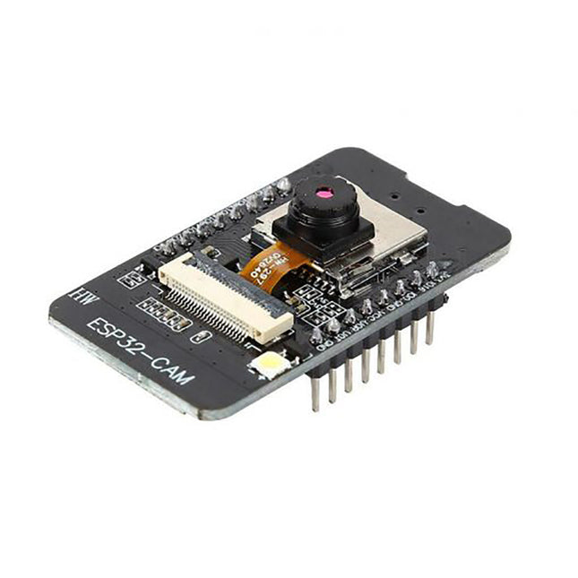
Espressif ESP32-Cam-CH340 Development Board
Features Product model: HW-818 Working voltage: DC 5V Product size: 27mm x 48.5 mm x 4.5 mm / 1.06” x 1.9” x 0.17” SPI Flash: Default 32Mbit RAM: Internal 520KB + External 4MPSRAM Bluetooth: Bluetooth 4.2 BR/EDR and BLE standards Wi-Fi: 802 II b/g/n/e/i Support interfaces: UART, SPI, I2C, PWM Supporting TF Card: Maximum Supporting 4G IO port: 9 Serial port rate: default 115200 BPS Image output format: JPEG (OV2640 only), BMP, GRAYSCALE Spectrum range: 2412-2484 MHz Antenna form: board PCB antenna, gain 2dBi Transmitting power: 802.l1b: 17 + 2dBm (1lMbps) 802.l1g:14+2dBm (54Mbps) 802.l1n:13+2dBm (MCS7)
€ 11,95
Members € 10,76
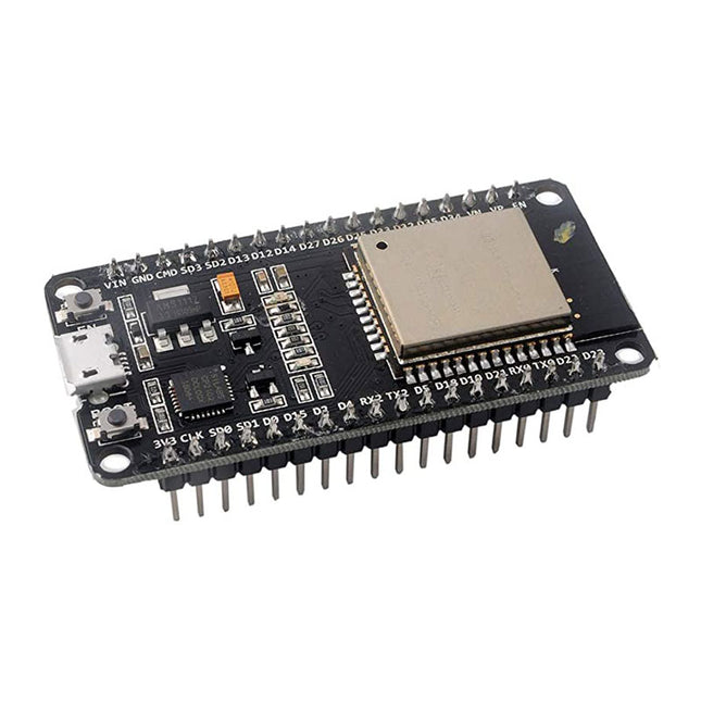
Espressif ESP32-DevKitC-32D
ESP32-DevKitC V4 is a small-sized ESP32-based development board produced by Espressif. Most of the I/O pins are broken out to the pin headers on both sides for easy interfacing. Developers can connect these pins to peripherals as needed. Standard headers also make development easy and convenient when using a breadboard. The board supports various ESP32 modules, including ESP32-WROOM-32, ESP32-WROOM-32U, ESP32-WROOM-32D, ESP32-SOLO-1, and ESP32-WROVER series. The following list and figure below describe key components, interfaces and controls of ESP32-DevKitC V4 board ESP32-WROOM-32 module soldered to the ESP32-DevKitC V4 board. Optional Space for ESP32-WROVER: Longer ESP32-WROVER modules may be soldered instead of the ESP32-WROOM-32. A single chip USB-to-UART bridge provides up to 3 Mbps transfers rates. Download button: holding down the Boot button and pressing the EN button initiates the firmware download mode. Then the user can download firmware through the serial port. EN Button: Reset button - pressing this button resets the system Micro USB Port: USB interface. It functions as the power supply for the board and the communication interface between PC and the ESP module. 5 V Power On LED: This LED lights when the USB or an external 5 V power supply is applied to the board. I/O Connector: Most of the pins on the ESP module are broken out to the pin headers on the board. Users can program ESP32 to enable multiple functions such as PWM, ADC, DAC, I2C, I2S, SPI, etc ESP32-DevKitC V4 schematic (PDF)
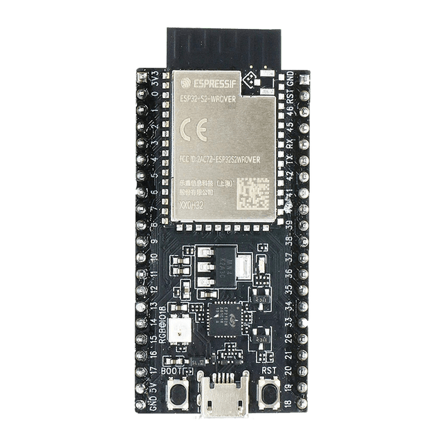
Espressif ESP32-S2-Saola-1R Development Board
ESP32-S2-Saola-1R is a small-sized ESP32-S2 based development board. Most of the I/O pins are broken out to the pin headers on both sides for easy interfacing. Developers can either connect peripherals with jumper wires or mount ESP32-S2-Saola-1R on a breadboard.ESP32-S2-Saola-1R is equipped with the ESP32-S2-WROVER module, a powerful, generic Wi-Fi MCU module that has a rich set of peripherals. It is an ideal choice for a wide variety of application scenarios relating to Internet of Things (IoT), wearable electronics and smart home. The board a PCB antenna and features a 4 MB external SPI flash and an additional 2 MB SPI Pseudo static RAM (PSRAM).FeaturesMCU ESP32-S2 embedded, Xtensa® single-core 32-bit LX7 microprocessor, up to 240 MHz 128 KB ROM 320 KB SRAM 16 KB SRAM in RTC WiFi 802.11 b/g/n Bit rate: 802.11n up to 150 Mbps A-MPDU and A-MSDU aggregation 0.4 µs guard interval support Center frequency range of operating channel: 2412 ~ 2484 MHz Hardware Interfaces: GPIO, SPI, LCD, UART, I²C, I²S, Camera interface, IR, pulse counter, LED PWM, TWAI (compatible with ISO 11898-1), USB OTG 1.1, ADC, DAC, touch sensor, temperature sensor 40 MHz crystal oscillator 4 MB SPI flash Operating voltage/Power supply: 3.0 ~ 3.6 V Operating temperature range: –40 ~ 85 °C Dimensions: 18 × 31 × 3.3 mm Applications Generic Low-power IoT Sensor Hub Generic Low-power IoT Data Loggers Cameras for Video Streaming Over-the-top (OTT) Devices USB Devices Speech Recognition Image Recognition Mesh Network Home Automation Smart Home Control Panel Smart Building Industrial Automation Smart Agriculture Audio Applications Health Care Applications Wi-Fi-enabled Toys Wearable Electronics Retail & Catering Applications Smart POS Machines
€ 22,95
Members € 20,66

Espressif ESP32-S2-Saola-1M Development Board
ESP32-S2-Saola-1M is a small-sized ESP32-S2 based development board. Most of the I/O pins are broken out to the pin headers on both sides for easy interfacing. Developers can either connect peripherals with jumper wires or mount ESP32-S2-Saola-1M on a breadboard.ESP32-S2-Saola-1M is equipped with the ESP32-S2-WROOM module, a powerful, generic Wi-Fi MCU module that has a rich set of peripherals. It is an ideal choice for a wide variety of application scenarios relating to Internet of Things (IoT), wearable electronics and smart home. The board a PCB antenna and features a 4 MB external SPI flash.FeaturesMCU ESP32-S2 embedded, Xtensa® single-core 32-bit LX7 microprocessor, up to 240 MHz 128 KB ROM 320 KB SRAM 16 KB SRAM in RTC WiFi 802.11 b/g/n Bit rate: 802.11n up to 150 Mbps A-MPDU and A-MSDU aggregation 0.4 µs guard interval support Center frequency range of operating channel: 2412 ~ 2484 MHz Hardware Interfaces: GPIO, SPI, LCD, UART, I²C, I²S, Camera interface, IR, pulse counter, LED PWM, TWAI (compatible with ISO 11898-1), USB OTG 1.1, ADC, DAC, touch sensor, temperature sensor 40 MHz crystal oscillator 4 MB SPI flash Operating voltage/Power supply: 3.0 ~ 3.6 V Operating temperature range: –40 ~ 85 °C Dimensions: 18 × 31 × 3.3 mm Applications Generic Low-power IoT Sensor Hub Generic Low-power IoT Data Loggers Cameras for Video Streaming Over-the-top (OTT) Devices USB Devices Speech Recognition Image Recognition Mesh Network Home Automation Smart Home Control Panel Smart Building Industrial Automation Smart Agriculture Audio Applications Health Care Applications Wi-Fi-enabled Toys Wearable Electronics Retail & Catering Applications Smart POS Machines
€ 29,95
Members € 26,96
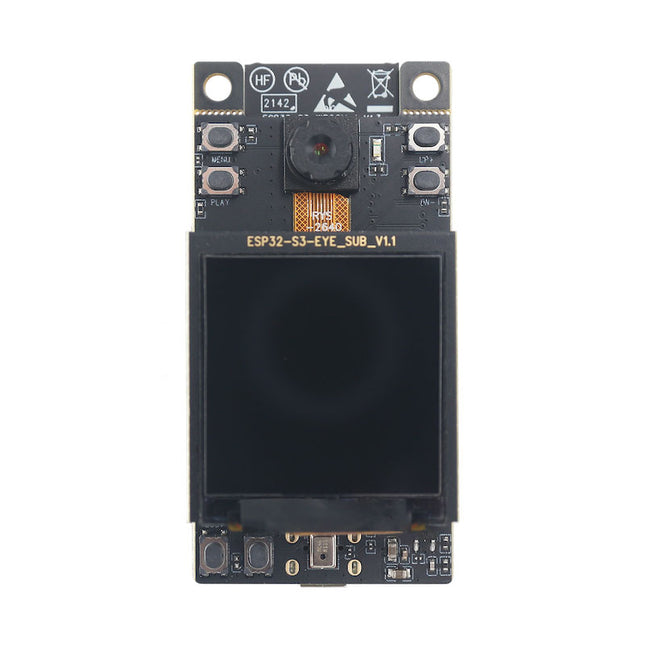
Espressif ESP32-S3-EYE
ESP32-S3-EYE is a small-sized AI development board. It is based on the ESP32-S3 SoC and ESP-WHO, Espressif’s AI development framework. The ESP32-S3-EYE board consists of two parts: the main board (ESP32-S3-EYE-MB) features the ESP32-S3-WROOM-1 module, a 2-Megapixel camera, a SD card slot, a digital microphone, a USB port, and function buttons; and the sub board (ESP32-S3-EYE-SUB) integrates an LCD display. The main board and sub board are connected through pin headers. ESP32-S3-EYE offers plenty of storage, with an 8 MB Octal PSRAM and a 8 MB flash. It also supports image transmission via Wi-Fi and debugging through a Micro-USB port. Specifications Camera The 2 MP camera OV2640 has a 66.5° field of view and a maximum resolution of 1600x1200. You can change the resolution when developing applications. Module Power LED The LED (green) turns on when USB power is connected to the board. If it is not turned on, it indicates either the USB power is not supplied, or the 5 V to 3.3 V LDO is broken. Software can configure GPIO3 to set different LED statuses (turned on/off, flashing) for different statuses of the board. Note: GPIO3 must be set up in open-drain mode. Pulling GPIO3 up may burn the LED. Pin Headers Connect the female headers on the sub board. 5 V to 3.3 V LDO Power regulator that converts a 5 V supply into a 3.3 V output for the module. Digital Microphone The digital I²S MEMS microphone features 61 dB SNR and –26 dBFS sensitivity, working at 3.3 V. FPC Connector Connects the main board and the sub board. Function Button There are six function buttons on the board. Users can configure any functions as needed except for the RST button. ESP32-S3-WROOM-1 The ESP32-S3-WROOM-1 module embeds the ESP32-S3R8 chip variant that provides Wi-Fi and Bluetooth 5 (LE) connectivity, as well as dedicated vector instructions for accelerating neural network computing and signal processing. On top of the integrated 8 MB Octal SPI PSRAM offered by the SoC, the module also comes with 8 MB flash, allowing for fast data access. ESP32-S3-WROOM-1U module is also supported. MicroSD Card Slot Used for inserting a MicroSD card to expand memory capacity. 3.3 V to 1.5 V LDO Power regulator that converts a 3.3 V supply into a 1.5 V output for the camera. 3.3 V to 2.8 V LDO Power regulator that converts a 3.3 V supply into a 2.8 V output for the camera. USB Port A Micro-USB port used for 5 V power supply to the board, as well as for communication with the chip via GPIO19 and GPIO20. Battery Soldering Points Used for soldering a battery socket to connect an external Li-ion battery that can serve as an alternative power supply to the board. If you use an external battery, make sure it has built-in protection circuit and fuse. The recommended specifications of the battery: capacity > 1000 mAh, output voltage 3.7 V, input voltage 4.2 V – 5 V. Battery Charger Chip 1 A linear Li-ion battery charger (ME4054BM5G-N) in ThinSOT package. The power source for charging is the USB Port. Battery Red LED When the USB power is connected to the board and a battery is not connected, the red LED blinks. If a battery is connected and being charged, the red LED turns on. When the battery is fully charged, it turns off. Accelerometer Three-axis accelerometer (QMA7981) for screen rotation, etc.
€ 59,95
Members € 53,96
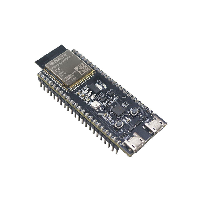
Espressif ESP32-S3-DevKitC-1U-N8R8
The ESP32-S3-DevKitC-1 is an entry-level development board equipped with ESP32-S3-WROOM-1U, a general-purpose Wi-Fi + Bluetooth Low Energy MCU module that integrates complete Wi-Fi and Bluetooth Low Energy functions. Most of the I/O pins on the module are broken out to the pin headers on both sides of this board for easy interfacing. Developers can either connect peripherals with jumper wires or mount ESP32-S3-DevKitC-1 on a breadboard. Features Module integrated: ESP32-S3-WROOM-1U-N8R8 Flash: 8 MB QD PSRAM: 8 MB OT SPI voltage: 3.3 V Specifications ESP32-S3-WROOM-1U ESP32-S3-WROOM-1U is a powerful, generic Wi-Fi + Bluetooth Low Energy MCU module that has a rich set of peripherals. It provides acceleration for neural network computing and signal processing workloads. ESP32-S3-WROOM-1U comes with an external antenna connector. 5 V to 3.3 V LDO Power regulator that converts a 5 V supply into a 3.3 V output. Pin Headers All available GPIO pins (except for the SPI bus for flash) are broken out to the pin headers on the board for easy interfacing and programming. USB-to-UART Port A Micro-USB port used for power supply to the board, for flashing applications to the chip, as well as for communication with the chip via the on-board USB-to-UART bridge. Boot Button Download button. Holding down Boot and then pressing Reset initiates Firmware Download mode for downloading firmware through the serial port. Reset Button Press this button to restart the system. USB Port ESP32-S3 full-speed USB OTG interface, compliant with the USB 1.1 specification. The interface is used for power supply to the board, for flashing applications to the chip, for communication with the chip using USB 1.1 protocols, as well as for JTAG debugging. USB-to-UART Bridge Single USB-to-UART bridge chip provides transfer rates up to 3 Mbps. RGB LED Addressable RGB LED, driven by GPIO38. 3.3 V Power On LED Turns on when the USB power is connected to the board. Downloads Pinout
€ 29,95
Members € 26,96


