Development Boards
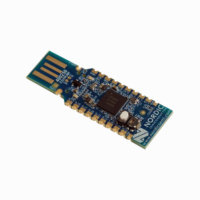
Nordic Semiconductor nRF52840 USB Dongle
The nRF52840 dongle is a small, low-cost USB dongle that supports Bluetooth 5.3, Bluetooth mesh, Thread, ZigBee, 802.15.4, ANT and 2.4 GHz proprietary protocols. The dongle is the perfect target hardware for use with nRF Connect for Desktop as it is low-cost but still support all the short range wireless standards used with Nordic devices. The dongle has been designed to be used as a wireless HW device together with nRF Connect for Desktop. For other use cases please do note that there is no debug support on the dongle, only support for programming the device and communicating through USB. It is supported by most of the nRF Connect for Desktop apps and will automatically be programmed if needed. In addition custom applications can be compiled and downloaded to the dongle. It has a user programmable RGB LED, a green LED, a user programmable button as well as 15 GPIO accessible from castellated solder points along the edge. Example applications are available in the nRF5 SDK under the board name PCA10059. The nRF52840 dongle is supported by nRF Connect for Desktop as well as programming through nRFUtil. Features Bluetooth 5.2 ready multiprotocol radio 2 Mbps Long Range Advertising Extensions Channel Selection Algorithm #2 (CSA #2) IEEE 802.15.4 radio support Thread ZigBee Arm Cortex-M4 with floating point support DSP instruction set ARM CryptoCell CC310 cryptographic accelerator 15 GPIO available via edge castellation USB interface direct to nRF52840 SoC Integrated 2.4 GHz PCB antenna 1 user-programmable button 1 user-programmable RGB LED 1 user-programmable LED 1.7-5.5 V operation from USB or external Downloads Datasheet Hardware Files
€ 19,95
Members € 17,96
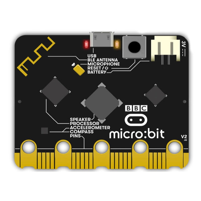
BBC micro:bit v2
Differences between micro:bit v1 and micro:bit v2 The BBC micro:bit v2 is equipped with BLE Bluetooth 5.0 It has a Power off button(push and hold power button) MEMS microphone with a LED indicator Onboard speaker Touch-sensitive logo pin LED power indicator A notched edge connector for easier connections.
€ 24,95
Members € 22,46
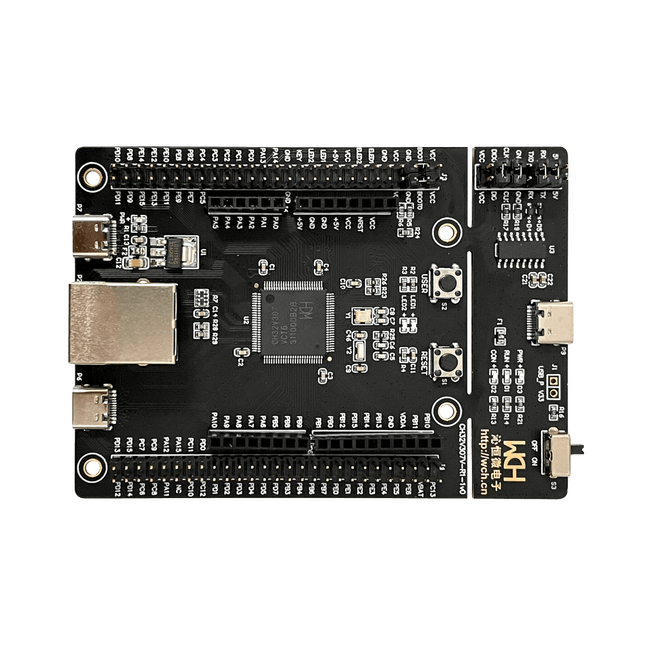
WCH CH32V307V-EVT-R1 RISC-V Development Board
WCH CH32V307 RISC-V development board features 8 UART ports controlled over Ethernet The CH32V307 is an interconnected microcontroller, based on 32-bit RISC-V core, with hardware stack area and fast interrupt entry. Compared with standard RISC-V, the interrupt response speed is greatly improved. With single-precision float point instruction sets added and stack area extended, the CH32V307 has higher performance, the number of U(S)ART is extended to 8, and the number of motor timer is extended to 4. The CH32V307 provides USB2.0 high-speed interface (480 Mbps) and has built-in PHY transceiver. Ethernet MAC is upgraded to GbE and integrates 10M PHY module. Features RISC-V4F processor, max 144 MHz system clock frequency Single-cycle multiplication and hardware division, hardware float point unit (FPU) 64KB SRAM, 256 KB Flash Supply voltage: 2.5 V/3.3 V, GPIO unit is supplied independently Multiple low-power modes: sleep/stop/standby Power-on/power-down reset (POR/PDR), programmable voltage detector (PVD) 2 general DMA controllers, 18 channels in total 4 amplifiers Single true random number generator (TRNG) 2x 12-bit DAC 2-unit 16-channel 12-bit ADC, 16-channel TouchKey 10 timers USB2.0 full-speed OTG interface USB2.0 high-speed host/device interface (built-in 480 Mbps PHY) 3 USARTs, 5 UARTs 2 CAN interfaces (2.0B active) SDIO interface, FSMC interface, DVP 2x I²C, 3x SPI, 2x I²S 80 I/O ports, can be mapped to 16 external interrupts CRC calculation unit, 96-bit unique chip ID Serial 2-wire debug interface Packages: LQFP64M, LQFP100 Downloads Datasheet GitHub
€ 19,95€ 11,95
Members identical
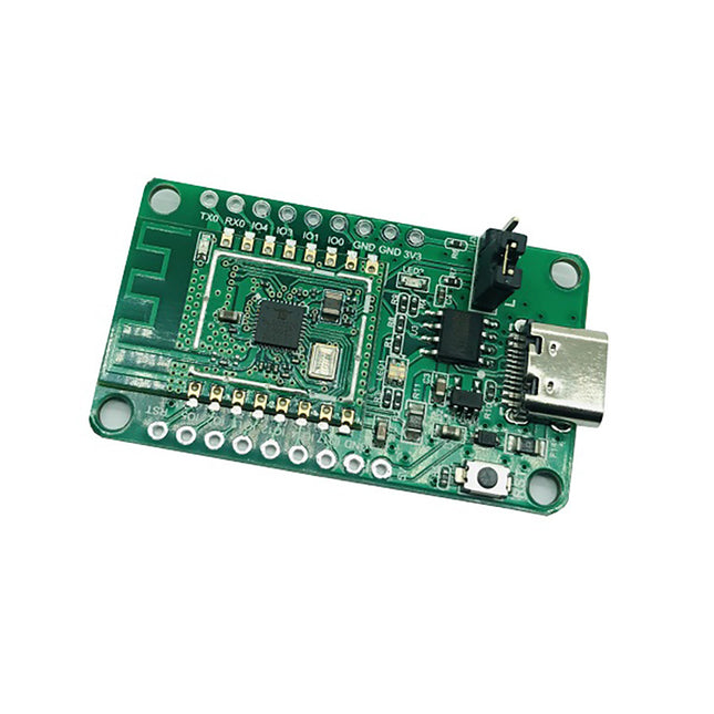
Pinecone BL602 Evaluation Board
Features Build in USB to Serial interface Build-in PCB antenna Powered by Pineseed BL602 SoC using Pinenut model: 12S stamp 2 MB Flash USB-C connection Suitable to breadboard BIY project On board three color LEDs output Dimensions: 25.4 x 44.0 mm Note: USB cable is not included.
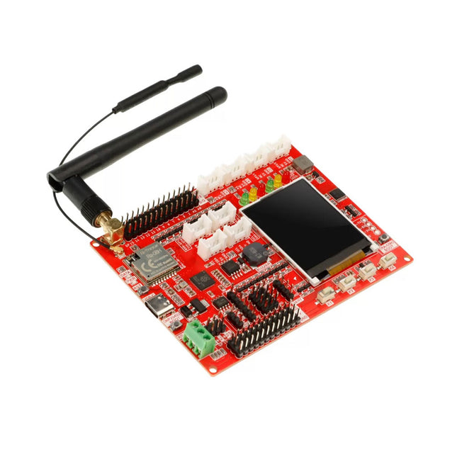
RA-08H LoRaWAN Development Board with integrated RP2040 and 1.8" LCD (EU868)
Lora technology and Lora devices have been widely used in the field of the Internet of Things (IoT), and more and more people are joining and learning Lora development, making it an indispensable part of the IoT world. To help beginners learn and develop Lora technology better, a Lora development board has been designed specifically for beginners, which uses RP2040 as the main control and is equipped with the RA-08H module that supports Lora and LoRaWAN protocols to help users realize development. RP2040 is a dual-core, high-performance, and low-power ARM Cortex-M0+ architecture chip, suitable for IoT, robots, control, embedded systems, and other application fields. RA-08H is made from the Semtech-authorized ASR6601 RF chip, which supports the 868 MHz frequency band, has a 32 MHz MCU built-in, which has more powerful functions than ordinary RF modules, and also supports AT command control. This board retains various functional interfaces for development, such as the Crowtail interface, the common PIN to PIN header that leads out GPIO ports, and provides 3.3 V and 5 V outputs, suitable for the development and use of commonly used sensors and electronic modules on the market. In addition, the board also reserves RS485 interface, SPI, I²C, and UART interfaces, which can be compatible with more sensors/modules. In addition to the basic development interfaces, the board also integrates some commonly used functions, such as a buzzer, a custom button, red-yellow-green three-color indicator lights, and a 1.8-inch SPI interface LCD screen with a resolution of 128x160. Features Uses RP2040 as the main controller, with two 32-bit ARM Cortex M0+ processor cores (dual-core), and provides more powerful performance Integrates the RA-08H module with 32 MHz MCU, supports the 868 MHz frequency band and AT command control Abundant external interface resources, compatible with Crowtail series modules and other common interface modules on the market Integrates commonly used functions like buzzer, LED light, LCD display and custom button, making it more concise and convenient when creating projects Onboard 1.8-inch 128x160 SPI-TFT-LCD, ST7735S driver chip Compatible with Arduino/Micropython, easy to carry out different projects Specifications Main Chip Raspberry Pi RP2040, built-in 264 KB SRAM, onboard 4 MB Flash Processor Dual Core Arm Cortex-M0+ @ 133 MHz RA-08H Frequency band 803-930 MHz RA-08H Interface External antenna, SMA interface or IPEX first-generation interface LCD Display Onboard 1.8-inch 128x160SPI-TFT-LCD LCD Resolution 128x160 LCD Driver ST7735S (4-wire SPI) Development environment Arduino/MicroPython Interfaces 1x passive buzzer 4x user-defined buttons 6x programmable LEDs 1x RS485 communication interface 8x 5 V Crowtail interfaces (2x analog interfaces, 2x digital interfaces, 2x UART, 2x I²C) 12x 5 V universal pin header IO 14x 3.3 V universal pin header IO 1x 3.3 V/5 V switchable SPI 1x 3.3 V/5 V switchable UART 3x 3.3 V/5 V switchable I²C Working input voltage USB 5 V/1 A Operating temperature -10°C ~ 65°C Dimensions 102 x 76.5 mm (L x W) Included 1x Lora RA-08H Development Board 1x Lora Spring Antenna (868 MHz) 1x Lora Rubber Antenna (868 Mhz) Downloads Wiki
€ 32,95
Members € 29,66
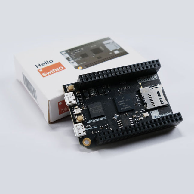
SwiftIO - Swift-based Microcontroller Board
SwiftIO offers a full Swift compiler and framework environment that runs on the microcontroller. The SwiftIO board is a compact electronic circuit board that runs Swift on the bare metal, giving you a system that can be used to control all kinds of electronic projects. Features NXP i.MX RT1052 Crossover Processor with ARM Cortex-M7 core @ 600 MHz 8 MB SPI Flash, 32 MB SDRAM On-board DAPLink debugger On-board USB to UART for serial communication On-board RGB LED On-board SD socket 46x GPIO, 12x ADC, 14x PWM, 4x UART, 2x I²C, 2x SPI etc. Many additional advanced features to meet the needs of advanced users Zephyr RTOS support MadMachine IDE is the premier integrated development environment for SwiftIO, which makes it easy to write Swift code and download it to the board.
€ 74,95€ 59,95
Members identical
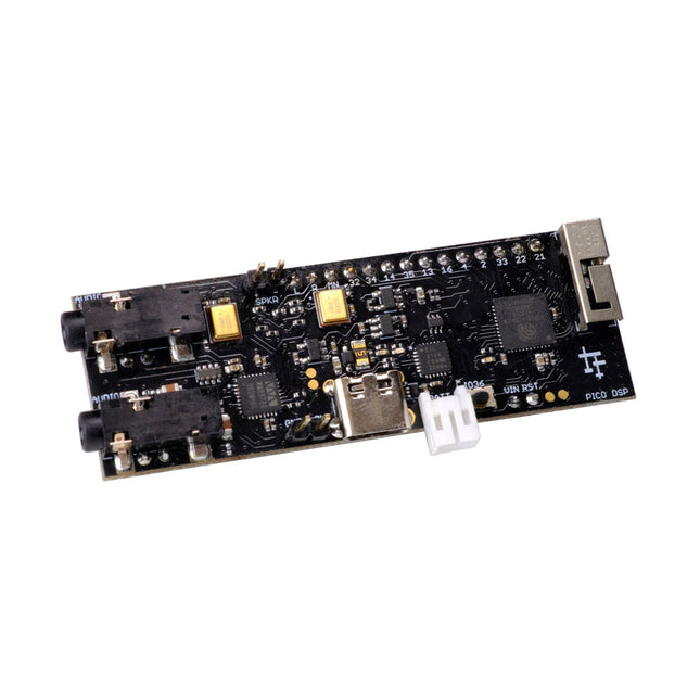
PÚCA DSP ESP32 Development Board
PÚCA DSP is an open-source, Arduino-compatible ESP32 development board for audio and digital signal processing (DSP) applications with expansive audio-processing features. It provides audio inputs, audio outputs, a low-noise microphone array, an integrated test-speaker option, additional memory, battery-charge management, and ESD protection all on a small, breadboard-friendly PCB. Synthesizers, Installations, Voice UI, and More PÚCA DSP can be used for a wide range of DSP applications, including but not limited to those in the fields of music, art, creative technology, and adaptive technology. Music-related examples include digital-music synthesis, mobile recording, Bluetooth speakers, wireless line-level directional microphones, and the design of smart musical instruments. Art-related examples include acoustic sensor networks, sound-art installations, and Internet-radio applications. Examples related to creative and adaptive technology include voice user interface (VUI) design and Web audio for the Internet of Sounds. Compact, Integrated Design PÚCA DSP was designed for portability. When used with an external 3.7 V rechargeable battery, it can be deployed almost anywhere or integrated into just about any device, instrument, or installation. Its design emerged from months of experimentation with various ESP32 development boards, DAC breakout boards, ADC breakout boards, Microphone breakout boards, and audio-connector breakout boards, and – despite its diminutive size – it manages to provide all of that functionality in a single board. And it dos so without compromising signal quality. Specifications Processor & Memory Espressif ESP32 Pico D4 Processor 32-bit dual core 80 MHz / 160 MHz / 240 MHz 4 MB SPI Flash with 8 MB additional PSRAM (Original Edition) Wireless 2.4 GHz Wi-Fi 802.11b/g/n Bluetooth BLE 4.2 3D Antenna Audio Wolfson WM8978 Stereo Audio Codec Audio Line In on 3.5 mm stereo onnector Audio Headphone / Line Out on 3.5 mm stereo connector Stereo Aux Line In, Audio Mono Out routed to GPIO Header 2x Knowles SPM0687LR5H-1 MEMS Microphones ESD protection on all audio inputs and outputs Support for 8, 11.025, 12, 16, 22.05, 24, 32, 44.1 and 48 kHz sample rates 1 W Speaker Driver, routed to GPIO Header DAC SNR 98 dB, THD -84 dB (‘A’ weighted @ 48 kHz) ADC SNR 95 dB, THD -84 dB (‘A’ weighted @ 48 kHz) Line input impedance: 1 MOhm Line output impedance: 33 Ohm Form Factor and Connectivity Breadboard friendly 70 x 24 mm 11x GPIO pins broken out to 2.54 mm pitch header, with access to both ESP32 ADC channels, JTAG and capacitive touch pins USB 2.0 over USB Type C connector Power 3.7/4.2 V Lithium Polymer Rechargeable Battery, USB or external 5 V DC power source ESP32 and Audio Codec can be placed into low power modes under software control Battery voltage level detection ESD protection on USB data bus Downloads GitHub Datasheet Links Crowd Supply Campaign (includes FAQs) Hardware Overview Programming the Board The Audio Codec
€ 69,95
Members € 62,96
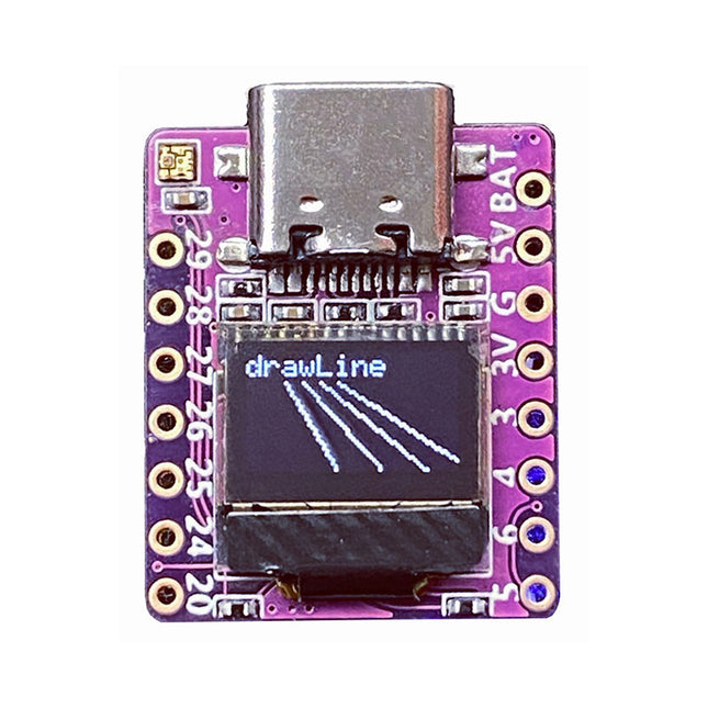
01Space RP2040-0.42LCD Development Board
Arduino, MicroPython, and CircuitPython-compatible compact development board powered by Raspberry Pi RP2040RP2040-0.42LCD is a high-performance development board with integrated 0.42' LCD (70x40 resolution) with flexible digital interfaces.It incorporates Raspberry Pi's RP2040 microcontroller chip. The RP2040 features a dual-core Arm Cortex-M0+ processor clocked at 133 MHz with 264 KB internal SRAM and 2 MB flash storage.Specifications SoC Raspberry Pi RP2040 dual-core Cortex-M0+ microcontroller at up to 125 MHz, with 264 KB SRAM Storage 2 MB SPI flash Display 0.42-inch OLED USB 1x USB Type-C port for power and programming Expansion – Qwiic I²C connector– 7-pin and 8-pin headers with up to 11x GPIOs, 2x SPI, 2x I²C, 4x ADC, 1x UART, 5 V, 3.3 V, VBAT, GND Misc – Reset and Boot buttons– RGB LED, power LED Power supply – 5 V via USB-C port or Vin– VBAT pin for battery input– 3.3 V regulator with 500 mA peak output Dimensions 23.5 x 18 mm Weight 2.5 g DownloadsGitHub
€ 19,95
Members € 17,96
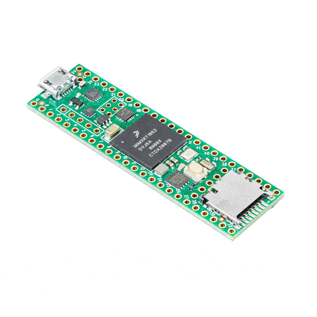
Teensy 4.1 Development Board
Specifications ARM Cortex-M7 at 600 MHz 2 USB ports, both 480 MBit/sec 2048K Flash (64K reserved for recovery & EEPROM emulation) 1024K RAM (512K is tightly coupled) 2 I2S Digital Audio 3 CAN Bus (1 with CAN FD) 1 S/PDIF Digital Audio 3 SPI, all with 16 word FIFO 1 SDIO (4 bit) native SD 3 I2C, all with 4 byte FIFO 7 Serial, all with 4 byte FIFO 32 general-purpose DMA channels 31 PWM pins 40 digital pins, all interrupt capable 14 analogue pins, 2 ADCs on chip Random Number Generator Cryptographic Acceleration Pixel Processing Pipeline RTC for date/time Peripheral cross triggering Programmable FlexIO Power On/Off management USB Host Teensy 4.1's USB Host port allows you to connect USB devices, like keyboards and MIDI musical instruments. A 5 pin header and a USB Host cable are needed to be able to plug in a USB device. You can also use one of these cables to connect to the USB pins. Memory The bottom side of Teensy 4.1 has locations to solder 2 memory chips. The smaller area is meant for a PSRAM SOIC-8 chip. The larger location is intended for QSPI flash memory. Power Consumption & Management When running at 600 MHz, the Teensy 4.1 consumes approximately 100mA current and provides support for dynamic clock scaling. Unlike traditional microcontrollers, where changing the clock speed causes wrong baud rates, and other issues, Teensy 4.1 hardware and Teensyduino's software support for Arduino timing functions are designed to allow dynamically speed changes. Serial baud rates, audio streaming sample rates, and Arduino functions like delay() and millis(), and Teensyduino's extensions like IntervalTimer and elapsedMillis, continue to work correctly while the CPU changes speed. Teensy 4.1 also provides a power shut off feature. By connecting a pushbutton to the On/Off pin, the 3.3V power supply can be completely disabled by holding the button for five seconds and turned back on by a brief button press. If a coin cell is connected to VBAT, Teensy 4.1's RTC also continues to keep track of date & time while the power is off. Teensy 4.1 furthermore can also be overclocked, well beyond 600MHz! The ARM Cortex-M7 brings many powerful CPU features to an accurate real-time microcontroller platform. The Cortex-M7 is a dual-issue superscaler processor, meaning the M7 can execute two instructions per clock cycle, at 600MHz! Of course, running two simultaneously depends upon the compiler ordering instructions and registers. Initial benchmarks have shown C++ code compiled by Arduino tends to achieve two instructions about 40% to 50% of the time while performing numerically intensive work using integers and pointers. The Cortex-M7 is the first ARM microcontroller to use branch prediction. On M4, loops and other code which use branch, it can take three clock cycles. With M7, after a loop has executed a few times, the branch prediction removes that overhead, allowing the branch instruction to run in only a single clock cycle. Tightly Coupled Memory is a unique feature which allows Cortex-M7 fast single-cycle access to memory using a pair of 64 bit wide buses. The ITCM bus provides a 64-bit path to fetch instructions. The DTCM bus is a pair of 32-bit paths, allowing M7 to perform up to two separate memory accesses in the same cycle. These extremely high-speed buses are different from M7's main AXI bus, which accesses other memory and peripherals. 512 of memory can be accessed as tightly coupled memory. Teensyduino automatically allocates your Arduino sketch code into ITCM, and all non-malloc memory use to the fast DTCM unless you add new keywords to override the optimized default. Memory not accessed on the tightly coupled buses is optimized for DMA access by peripherals. Because the bulk of M7's memory access is done on the two tightly coupled buses, powerful DMA-based peripherals have excellent access to the non-TCM memory for highly efficient I/O. Teensy 4.1's Cortex-M7 processor includes a floating-point unit (FPU) which supports both 64 bit 'double' and 32-bit 'float'. With M4's FPU on Teensy 3.5 & 3.6, and also Atmel SAMD51 chips, only 32-bit float is hardware accelerated. Any use of double, double functions like log(), sin(), cos() means slow software implemented math. Teensy 4.1 executes all of these with FPU hardware. For more information, check out the official Teensy 4.1 page here.
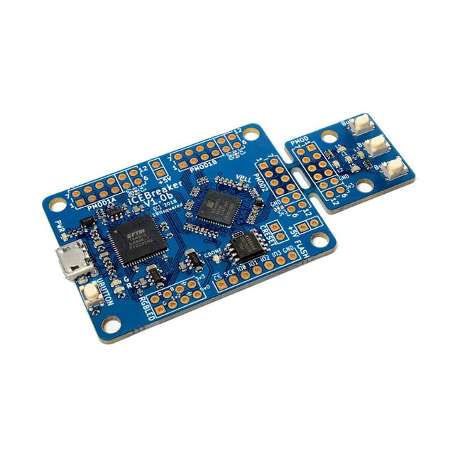
iCEBreaker FPGA Development Board
The iCEBreaker FPGA board is an open-source educational FPGA development board. The iCEBreaker is great for classes and workshops teaching the use of the open source FPGA design flow through Yosys, nextpnr, IceStorm, Icarus Verilog, Amaranth HDL and others. This means the board is low cost and has a nice set of features to allow for the design of interesting classes and workshop exercises. At the same time it allows the user to use the proprietary vendor tools if they choose to. After the workshop the boards can be easily used as a development board as most GPIO are exposed, broken out and configurable through jumpers on the back of the board. There is only a minimal amount of buttons and LED that can't be disconnected and used for your own purposes. Documentation Workshop
€ 89,95
Members € 80,96


