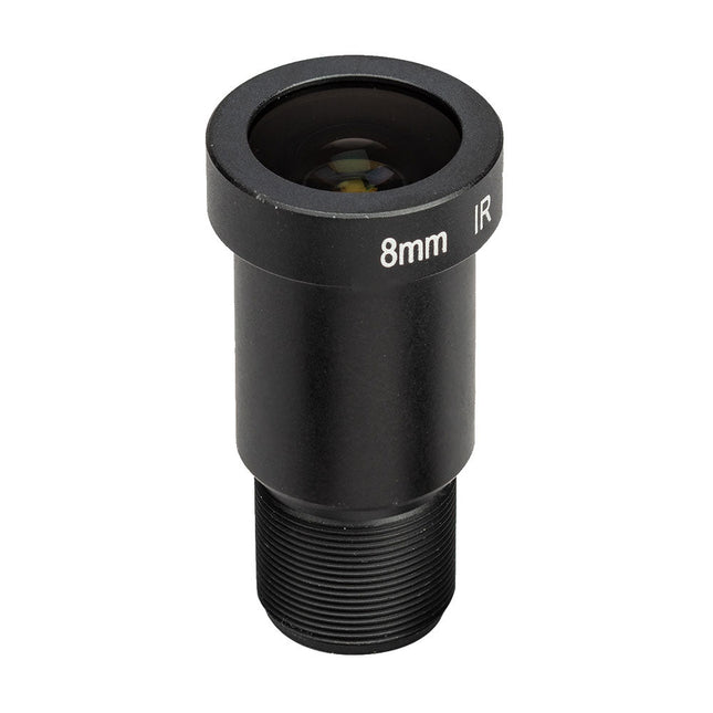
The M12 Mount Lens (12 MP, 8 mm) is ideal for use with the Raspberry Pi HQ Camera Module, offering sharp and detailed imaging for a wide range of applications.
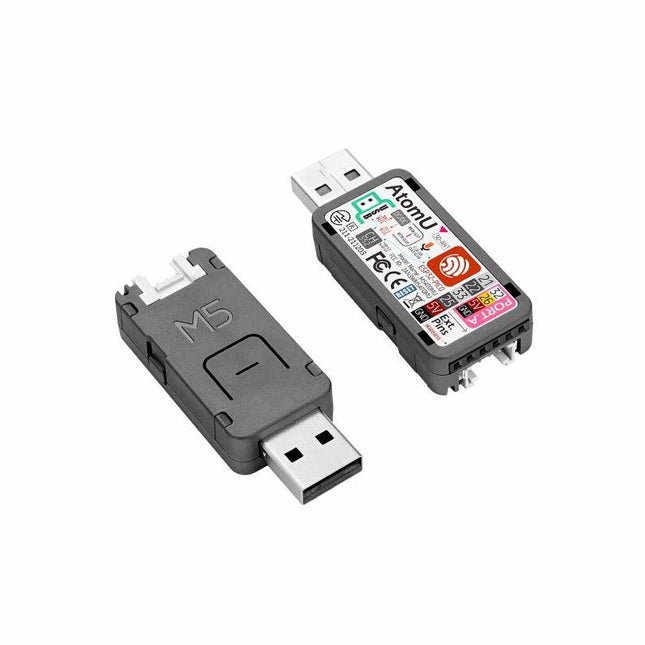
ATOM U is a compact low-power consumption speech recognition IoT development kit. It adopts an ESP32 chipset, equipped with 2 low-power Xtensa 32-bit LX6 microprocessors with the main frequency of up to 240 MHz. Built-in USB-A interface, IR emitter, programmable RGB LED. Plug-and-play, easy to upload and download programs. Integrated Wi-Fi and digital microphone SPM1423 (I2S) for the clear sound record. suitable for HMI, Speech-to-Text (STT). Low-code development ATOM U supports UIFlow graphical programming platform, scripting-free, cloud push; Fully compatible with Arduino, MicroPython, ESP32-IDF, and other mainstream development platforms, to quickly build various applications. High integration ATOM U contains a USB-A port for programming/power supply, IR emitter, programmable RGB LED x1, button x1; Finely tuned RF circuit, providing stable and reliable wireless communication. Strong expandability ATOM U is easy access to M5Stack's hardware and software system. Features ESP32-PICO-D4 (2.4GHz Wi-Fi dual mode) Integrated programmable RGB LED and button Compact design Built-in IR emitter Expandable pinout and GROVE port Development platform: UIFlow MicroPython Arduino Specifications ESP32-PICO-D4 240MHz dual core, 600 DMIPS, 520KB SRAM, 2.4G Wi-Fi Microphone SPM1423 Microphone sensitivity 94 dB SPL@1 KHz Typical value: -22 dBFS Microphone signal-to-noise ratio 94 dB SPL@1 KHz, A-weighted Typical value: 61.4 dB Standby working current 40.4 mA Support input sound frequency 100 Hz ~ 10 KHz Support PDM clock frequency 1.0 ~ 3.25 MHz Weight 8.4 g Product size 52 x 20 x 10 mm Downloads Documentation
Features Compatible with Raspberry Pi 4 only
Cutout in lid for 40x30mm heatsink or Fan SHIM
Super-slimline profile Fully HAT-compatible Protects your beloved Pi Clear top and base leave Raspberry Pi 4 visible GPIO cut-out Handy laser-etched port labels Leaves all ports accessible Made from lightweight, high-quality, cast acrylic Great for hacking and tinkering! Made in Sheffield, UK Weighing just over 50 grams, the case is lightweight and ideal for mounting to any surface. No tools are required for assembly or disassembly. The dimensions are: 99 × 66 × 15 mm. In the video below you can see a quick assembly guide.
Take control of and monitor your world with this ultimate jack-of-all-trades Raspberry Pi HAT!
This home monitoring and automation controller is packed with features to supercharge Raspberry Pi projects. With relays, analog channels, powered outputs, and buffered inputs (all 24 V tolerant), a wide range of devices and sensors can be connected simultaneously.
Each channel includes its own indicator LED for instant status feedback. Even the analog channels feature dimming LEDs that reflect live sensor values—smooth and practical.
Ideal for smart home and automation projects such as greenhouse irrigation, automated fish feeding, or customized scheduling.
Features
3x 24 V @ 2 A relays (NC and NO terminals)
3x 12-bit ADC @ 0-24 V (±2% accuracy)
3x 24 V tolerant buffered inputs
3x 24 V tolerant sinking outputs
15x channel indicator LEDs
1x 12-bit ADC @ 0-3.3 V
3.5 mm screw terminals
Power, Comms, and Warn! LED indicators
SPI, TX (#14), RX (#15), #25 pins broken out
Automation HAT pinout
Compatible with all 40-pin header Raspberry Pi models
Python library
Schematic
Comes fully assembled (broken out pins require soldering)
Software
As ever, we've made a super-simple to use Python library to take advantage of Automation HAT's multitudinous functions, with examples to get you started.
Our input, output and relay examples show you how to read the analog and digital inputs, switch the outputs on and off, and control the relays.
Notes
We recommend you use a set of brass M2.5 standoffs with Automation HAT to avoid pins contacting the HDMI port if the HAT is pushed down
Loads for the buffered outputs should be switched on the ground side, i.e. 12/24 V (from supply) -> load -> output terminal -> ground (from supply)
The relays can tolerate up to 2 A each and should be switched on the high side
The sinking outputs can sink a maximum 500 mA total across the 3 outputs, so if you use a single channel you can sink the whole 500 mA across it.
The accuracy of the ADC is ±2%.
Do not use to switch mains voltages!
This 10.1-inch HDMI touch screen has a high-definition resolution of 1280x800 and supports a viewing angle of 178°, providing an excellent visual experience. It supports Raspberry Pi, Windows, Linux, Ubuntu and other systems, and is also compatible with Raspberry Pi 3/3B+/4B/5, Jetson Nano, Beaglebone, Banana Pi and other mainstream development boards. You can easily adjust the desired brightness by adjusting the backlight button.
This Raspberry Pi capacitive touch screen supports 5-point touch, has fast response speed, and high-definition communication supports plug-and-play.It comes with a stand for easy desktop placement, and mounting holes on the back allow you to securely mount it on a wall or integrate it with a small form factor SBC (single board computer).
To protect the screen and enhance its visual appeal, the monitor comes with a durable and stylish acrylic cover.
Whether you need a high-quality monitor for gaming, multimedia entertainment, or industrial applications, our 10-inch monitors offer superior visuals, responsive touch controls, seamless connectivity, and versatile mounting options.
Features
IPS HD 1280x800 resolution and 178° full viewing angle offers crystal clear visuals and vivid colors for high-quality visual experience
Support backlight control, itcan be adjusted by button
Support capacitive 5-point touch, enable smooth, accurate and fast response
Use HD communication, plug and play, and easy to use
Support Windows, Linux, Ubuntu, Kodi, etc.
Compatible with Raspberry Pi 3/3B+/4B/5, Jetson Nano, Beaglebone
Specifications
Screen Size
10.1 inch
Screen Type
IPS screen
Resolution
1280 x 800
Backlight adjustment
Key switch adjustment
Touch Screen Type
Capacitive Touch Screen
Touch IC
SIS9200
Power
Micro-USB (5 V)
Overall power
5.2942 W (100% brightness)
Video Input Interface
HDMI-Compatible (up to 1080p)
Active Area
216.6 x 135.4 mm
Dimensions (L x W x H)
239.4 x 157.4 x 12.3 ±0.2 mm
Included
1x 10.1 inch Touch Display
1x HD to HD Cable
2x USB cable
1x HD to Mini HD Adapter
1x Screw Pack
2x Bracket
1x Screwdriver
1x Manual
Downloads
Manual
Wiki
Elektor GREEN and GOLD members can download their digital edition here.
Not a member yet? Click here.
PbMonitor v1.0A Battery-Monitoring System for UPS and Energy Storage Applications
Solar Charge Controller with MPPT (1)Basic Principles of a Solar Controller for Stand-Alone Systems
B-Field Integration Magnetometer With Home-Made Sensors
Precise or Accurate?Your Instruments Need to Be Both!
AD7124 A Precision ADC in PracticeFeatures for Sensor Signal Conditioning
PID Control ToolOptimize Your Parameters Easily
embedded world 2025
Starting Out in Electronics……Continues with Tone Control
Academy Pro BoxBook + Online Course + Hardware
Milliohmmeter AdapterUses the Precision of Your Multimeter
The Next Leap in SemiconductorsOnward Toward 1.4 nm
Through-Hole Technology ConnectorsThe Best of Two Worlds: THR
Frequency CounterPortable and Auto-Calibrating Via GPS
Analog MetersPeculiar Parts, the Series
Stand-Alone Crystal TesterHow Accurate Is Your Clock Source?
Low-Cost I²C TesterConnect I²C Devices Directly to Your PC
From Life’s ExperienceWho Doesn’t Honor the Small Things?
2025: An AI OdysseyThe Transformative Impact on Software Development
Err-lectronicsCorrections, Updates, and Readers’ Letters
Raspberry Pi Standalone MIDI Synthesizer (2)Enhancing Our Setup with Intelligence
Nortonized Wien Bridge OscillatorSmall Changes Yield Significant Improvements
Putting a $0.10 Controller to the TestThe CH32V003 RISC-V Microcontroller and MounRiver Studio in Practice
An FPGA-Based Audio Player with Equalizer (2)Adding Volume Control, Advanced Mixing, and a Web Interface
Elektor GREEN and GOLD members can download their digital edition here.
Not a member yet? Click here.
The Raspberry Pi 5A Huge Improvement From Its Predecessor
AI in the Electronics LabGoogle Bard and Flux Copilot Put to the Test
Arduino Nano Waveform GeneratorNano + Code = Function Generator
Solar-Powered Christmas GarlandAn Eco-Friendly Solution for Garnishing Your Balcony
USB Killer DetectorBetter Safe Than Sorry
A Simple CNCed EnclosureWith Autodesk Fusion 360 for Personal Use
Low-Volume Board ProductionWith and without Assembly
IoT Simulation Simplified with WokwiDeveloper Uri Shaked on Design, Software, and More
A Bare-Metal Programming Guide (Part 3)CMSIS Headers, Automatic Testing, and a Web Server
LoRa, a Swiss Army Knife (2)The Hardware and Software
MEMS Microphone Design and Construction
Tools to Try Before You SolderSimulation and 3D Modeling Tools That Can Be Used for Free
New Tools From Microchip!PICkit 5 and MPLAB ICD 5 Available Now!
Rapid Prototyping of Flexible, Stretchable ElectronicsHow the Voltera NOVA Speeds Up Innovation in Wearable Electronic Systems
Galvanic IsolationUsing Phototransistor Optocouplers Successfully
The Complex Solution or the Anybus Solution?Embedded Industrial Ethernet in 2 Days Rather Than Many Months
Your Essential DFM ChecklistHow to Start Designing for Manufacture
3D Printing FilamentsTypes, Features and Use in Prototyping
Specialists for Effective Signal Analysis from ELF to EHF BandAaronia’s latest real-time SPECTRAN® V6 series spectrum analyzers
Challenges of DFM Analysis for Flex and Rigid-Flex Design
Setting Up an SMT Line
The Right Combination for a Reliable Assembly
Revolutionizing IndustriesThe Rise of Autonomous Mobile Robots (AMRs)
Evolved for More ChallengesRohde & Schwarz Adds Eight-Channel R&S MXO 5 to Next-Generation Oscilloscopes
Starting Out in Electronics……Amplifying Differences
Mini Reflow PlateFor Assembling or Repairing Small SMD Circuits
Don’t Start with a Prototype – Start with a Pretotype!Check That a Market Exists for Your Product Before Warming Your Soldering Iron
2023: An AI OdysseyGetting Help Designing a Physical Project
Brussels Is InnovatingSupport for Deep Tech
Elektor GREEN and GOLD members can download their digital edition here.
Not a member yet? Click here.
Project Update: ESP32-Based Energy MeterNext Steps in Prototyping
Optimizing Balcony Power PlantsConsiderations, Interesting Facts, and Calculations
ESP32 With OpenDTU for Balcony Power PlantsRead Data from Small Inverters Via MCUs
Variable Linear Power Supply Ensemble0…50 V / 0…2 A + Dual Symmetrical Supply
Energy Storage Today and TomorrowAn Interview With Simon Engelke
2024: An AI OdysseyIt’s Not Letting Up
Bluetooth LE on the STM32A Way to Read Measurements Remotely
Human-Centric Smart Kitchen Grocery Container
MAUI: Programming for PC, Tablet, and SmartphoneThe New Framework in Theory and Practice
ChatMagLevThe AI Way of Levitation
Simple PV Power RegulatorBuild Your First, Fully Functional PV Energy Management System
Cold-Cathode DevicesPeculiar Parts, the Series
From Life’s ExperienceNostalgia
Starting Out in Electronics……Looking at FETs
CAN Bus Tutorial for the Arduino UNO R4Two UNO R4s Hop on the Bus!
Infographics: Power & Energy
Comprehensive Design and Development SupportArrow Engineering Services
Comparing Power Density and Power Efficiency
Aluminium Electrolytic CapacitorsInterference Potential in Audio Technology
USB Test and MeasurementThe Fnirsi FNB58
The Pixel Pump Pick-and-Place ToolSimplifying Manual SMT Board Assembly
HomeLab ToursNot So Long Ago, in a Far-Away Country...
“In the world of ethics in electronics, even small steps can make a significant impact.”
Ethics in ElectronicsThe OECD Guidelines and Germany’s Supply Chain Due Diligence Act
Chadèche: Smart Ni-MH Charger/DischargerA Reader’s Project in Brief
Err-lectronicsCorrections, Updates and Readers’ Letters
YDLIDAR SDM18 is a high-performance single-point LiDAR. Based on the principle of ToF, it is equipped with related optics, electricity, and algorithm design to achieve high-precision laser distance measurement and outputting high frame rate point cloud data of the scanning environment. It can be used for UAV alt-hold, robot obstacle avoidance and navigation, etc.
Specifications
High Ranging frequency: 50-250 Hz
Range Distance: 0.2-18 m
FDA Class I eye safety standard
Support UART and I²C interfaces
Dimensions: 21 x 15 x 7.87 mm
Weight: 1.35 g
Applications
UAV alt-hold and obstacle avoidance
Robot obstacle avoidance
Intelligent equipment obstacle avoidance
Navigation and obstacle avoidance of home service robots / robot vacuum cleaners
Downloads
Datasheet
User Manual
Development Manual
SDK
Tool
ROS
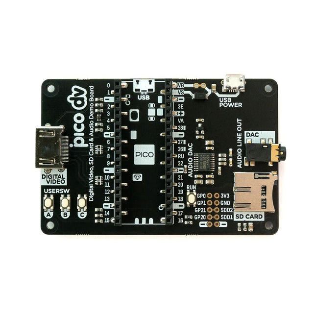
This board is an all-digital conversion of Raspberry Pi's VGA reference design, great for if you want to start hacking on video and/or audio output from a Raspberry Pi Pico and piping it straight into a modern monitor.Features
HDMI connector
PCM5100A DAC for line out audio over I²S (datasheet)
SD card slot
Reset button
Socket headers to install your Raspberry Pi Pico
Three user-controllable switches
Rubber feet
Compatible with Raspberry Pi Pico
No soldering required (as long as your Pico has header pins attached)
Programmable with C/C++
Note: Raspberry Pi Pico is not included. Your Pico will need to have pin headers soldered to it (with the pins pointing downwards) to attach to our add-on boards.Downloads
Schematic
GitHub
This tiny little board does all of the neat Arduino tricks that you're familiar with: nine channels of 10-bit ADC, five PWM pins, 12 DIOs as well as hardware serial connections Rx and Tx. Running at 5 V and 16 MHz, this board will remind you a lot of your other favourite Arduino-compatible boards, but this little guy can go just about anywhere. There is a voltage regulator on board so it can accept voltage up to 6 VDC. If you're supplying unregulated power to the board, be sure to connect to the 'RAW' pin on not VCC.
The reset button's benefit is to quickly reset the board or place it into bootloader mode without the need to take out a piece of the jumper wire. The USB micro-b connector has been replaced with the USB type C connector.
The through-hole pads have castellated edges for each pin to add a lower profile in your projects should you decide to build it into another assembly during production. Finally, a Qwiic connector is populated on the board's bottom to add Qwiic enabled I²C devices to your projects easily!
Features
ATmega32U4 running at 5 V / 16 MHz
AP2112 3.3 V Voltage Regulator
Supported under Arduino IDE v1.0.1+
On-Board USB-C connector for programming
PTH Pads w/ Castellated Edges
9 x 10-bit ADC pins
12 x Digital I/Os (5 are PWM capable)
Hardware Serial Connections
UART (i.e. Rx and Tx)
Qwiic Connector for I²C
SPI
Small Arduino-Compatible Board
Reset Button
Dimensions: 1.3in x 0.7in
The board provides you with an economical and easy to use development platform if you're needing more power with minimal working space. With the M.2 MicroMod connector, connecting your SAMD51 Processor is a breeze. Simply match up the key on your processor's bevelled edge connector to the key on the M.2 connector and secure it with a screw (included with all Carrier Boards). The SAMD51 is one of the most powerful and economical microcontrollers available so to be able to add it to your MicroMod Carrier Board is a huge advantage for your project!
The ATSAMD51J20 utilizes a 32-bit ARM Cortex-M4 processor with Floating Point Unit (FPU), running up to 120MHz, up to 1MB of flash memory, up to 256KB of SRAM with ECC, up to 6 SERCOM interfaces, and other features. This MicroMod SAMD51 even comes flashed with the same convenient UF2 bootloader as the SAMD51 Thing Plus and the RedBoard Turbo.
Features
ATSAMD51J20 microcontroller
32-bit ARM Cortex-M4F MCU
Up to 120 MHz CPU speed
1 MB flash memory
256 KB SRAM
Up to 6 SERCOM interfaces
UF2 bootloader
1x USB dedicated for programming and debug (Host capable)
2x UARTs
2x I²C
1x SPI
1x CAN
11x GPIO
2x Digital Pins
2x Analog Pins
2x PWM
128 mbit / 16 MB (external) flash memory
Status LED
VIN Level ADC
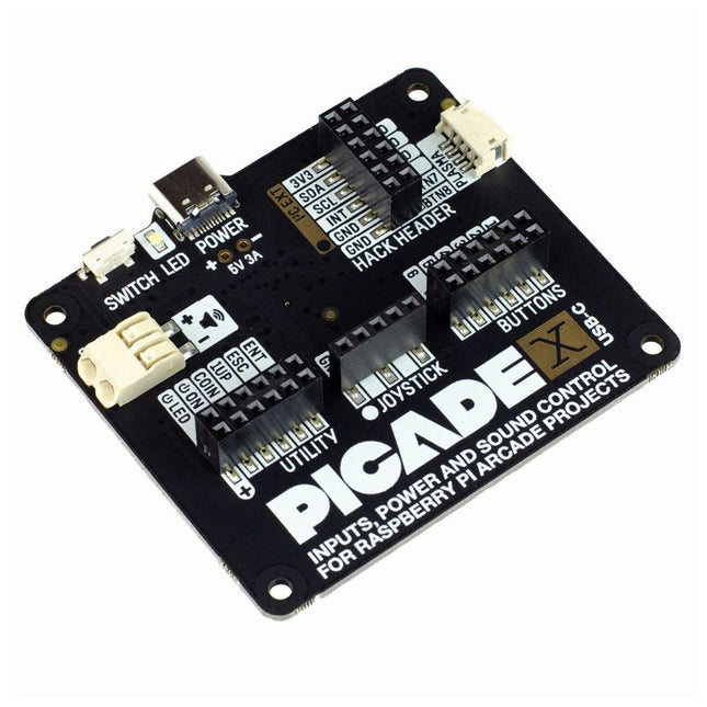
Turn your Raspberry Pi into a retro games console! Picade X HAT includes joystick and button inputs, a 3 W I²S DAC/amplifier, and soft power switch. This HAT has all the same great features as the original Picade HAT but now has no-fuss female Dupont connectors to hook up your joystick and buttons. Simply pop Picade X HAT onto your Pi, plug a USB-C power supply into the connector on the HAT (it back-powers your Pi through the GPIO, so no need for a separate power supply), wire up your controls, and install the driver! It's ideal for your own DIY arcade cabinet builds, or for interfaces that need big, colourful buttons and sound. Features I²S audio DAC with 3 W amplifier (mono) and push-fit terminals Safe power on/off system with tactile power button and LED USB-C connector for power (back-powers your Pi) 4-way digital joystick inputs 6x player button inputs 4x utility button inputs 1x soft power switch input 1x power LED output Plasma button connector Breakout pins for power, I²C, and 2 additional buttons Picade X HAT pinout Compatible with all 40-pin Raspberry Pi models The I²S DAC blends both channels of digital audio from the Raspberry Pi into a single mono output. This is then passed through a 3 W amplifier to power a connected speaker. The board also features a soft power switch that allows you turn your Pi on and off safely without risk of SD card corruption. Tap the connected button to start up, and press and hold it for 3 seconds to fully shutdown and disconnect power. Software/Installation Open a terminal and type curl https://get.pimoroni.com/picadehat | bash to run the installer. You'll need to reboot once the installation is complete, if it doesn't prompt you to do so. The software does not support Raspbian Wheezy Notes With USB-C power connected through Picade X HAT you'll need either to tap the connected power button or the button marked 'switch' on the HAT to power on your Pi.
Quite unintentionally a one-page story on an old Heathkit tube tester in the December 2004 edition of Elektor magazine spawned dozens of ‘Retronics’ tales appearing with a monthly cadence, and attracting a steady flow of reader feedback and contributions to the series. Since launching his Retronics columns, Elektor Editor Jan Buiting has never been short of copy to print, or vintage equipment to marvel at.
This book is a compilation of about 80 Retronics installments published between 2004 and 2012. The stories cover vintage test equipment, prehistoric computers, long forgotten components, and Elektor blockbuster projects, all aiming to make engineers smile, sit up, object, drool, or experience a whiff of nostalgia.
To reflect that our memories are constantly playing tricks on us, and honoring that “one man’s rubbish is another man’s gem”, the tales in the book purposely have no chronological order, and no bias in favor of transistor or tube, microprocessor or discrete part, audio or RF, DIY or professional, dry or narrative style.
Although vastly diff erent in subject matter, all tales in the book are told with personal gusto because Retronics is about sentiment in electronics engineering, construction and repair, be it to reminisce about a 1960s Tektronix scope with a cleaning lady as a feature, or a 1928 PanSanitor box for dubious medical use.
Owners of this book are advised to not exceed one Retronics tale per working day, preferably consumed in the evening hours under lamp light, in a comfortable chair, with a piece of vintage electronic equipment close and powered up.
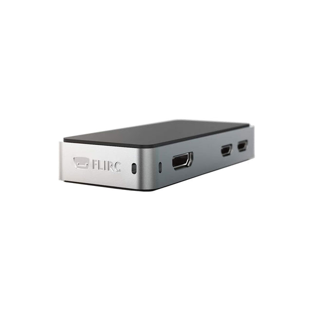
The FLIRC Raspberry Pi Zero Case is compatible with Raspberry Pi Zero W and the newer Raspberry Pi Zero 2 W.
The design of the FLIRC Zero Case is based on the original FLIRC case. As with the original, the aluminum housing serves as protection and, thanks to the contact point on the processor, as a passive cooler. Ideal for silent operation.
In addition to a normal cover that encloses and protects the Raspberry Pi Zero, there is a second cover that allows access to the GPIO pins through a small opening.
Elektor GREEN and GOLD members can download their digital edition here.
Not a member yet? Click here.
STM32 Wireless Innovation Design Contest Winners
In-Circuit LC MeterA Prototype Study
The AmpVolt Modular DC Power Meter (Part 1)Measure DC Power and Energy Consumption Up to 50 V and 5 A
embedded world 2024
Repairing Electronic EquipmentTools, Techniques and Tips
Starting Out in Electronics…...Continues the Opamp Theory
A Simple DDS Signal GeneratorDirect Digital Synthesis in Its Purest Form
Sparkplug at a GlanceA Specification for MQTT Data
The CRTCPeculiar Parts, the Series
Radar-Controlled LightingAutomatic Stairway Light With Human Presence Detection
Digital Bubble Level and Active Stroboscopic Disc for TurntablesFine-Tune Your Record Player With This All-In-One Tool
Open Source and Its Significance for the Electronics Industry (2)
M12 Circular Connector With A-codingFirst Choice for Industrial Applications
The Arduino-Inside Measurement LabAn 8-in-1 Test & Measurement Instrument for the Electronics Workbench
Sound Card Performs Gain/Phase and Impedance AnalysisFor Frequencies From 100 Hz to 90 kHz
Measuring pH Value With the Arduino UNO R4Check the Quality of Your Water
From Life’s ExperiencePangpong Butt Launcher
FNIRSI 1014D Digital Storage OscilloscopeGood Performance for Tight Budgets
2024: An AI OdysseyGetting Object Detection Up and Running
10 MHz Reference GeneratorHighly Accurate, With Distributor and Galvanic Isolation
Project Update #2: ESP32-Based Energy MeterSome Enhancements
Err-lectronicsCorrections, Updates, and Readers’ Letters
An Interview with Eben Upton, CEO of Raspberry PiRaspberry Pi 5 and Beyond
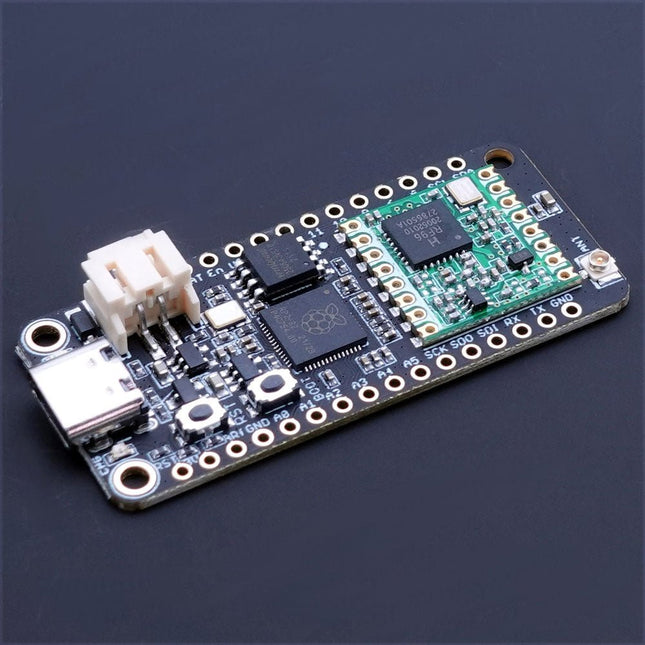
The Challenger RP2040 LoRa is an Arduino/CircuitPython compatible Adafruit Feather format microcontroller board based on the Raspberry Pi Pico (RP2040) chip.The transceiver features a LoRa long range modem that provides ultra-long range spread spectrum communication and high interference immunity whilst minimizing current consumption.LoRaThe integrated module LoRa module (RFM95W) can achieve a sensitivity of over -148 dBm utilizing a low cost crystal and bill of materials. The high sensitivity combined with the integrated +20 dBm power amplifier yields industry leading link budget making it optimal for any application requiring range or robustness. LoRa also provides significant advantages in both blocking and selectivity over conventional modulation techniques, solving the traditional design compromise between range, interference immunity and energy consumption.The RFM95W is connected to the RP2040 via SPI channel 1 and a few GPIO’s that is required for signaling. A U.FL connector is used to attach your LoRa antenna to the board.
168 dB maximum link budget
+20 dBm – 100 mW constant RF output vs. V supply
+14 dBm high efficiency PA
Programmable bit rate up to 300 kbps
High sensitivity: down to -148 dBm
Bullet-proof front end: IIP3 = -12.5 dBm
Excellent blocking immunity
Low RX current of 10.3 mA, 200 nA register retention
Fully integrated synthesizer with a resolution of 61 Hz
FSK, GFSK, MSK, GMSK, LoRaTM and OOK modulation
Built-in bit synchronizer for clock recovery
Preamble detection
127 dB Dynamic Range RSSI
Automatic RF Sense and CAD with ultra-fast AFC
Packet engine up to 256 bytes with CRC
Specifications
Microcontroller
RP2040 from Raspberry Pi (133 MHz dual-core Cortex-M0)
SPI
Two SPI channels configured (second SPI connected to RFM95W)
I²C
One I²C channel configured
UART
One UART channel configured
Analog inputs
4 analog input channels
Radio module
RFM95W from Hope RF
Flash memory
8 MB, 133 MHz
SRAM memory
264 KB (divided into 6 banks)
USB 2.0 controller
Up to 12 MBit/s full speed (integrated USB 1.1 PHY)
JST Battery connector
2.0 mm pitch
On board LiPo charger
450 mA standard charge current
Dimensions
51 x 23 x 3,2 mm
Weight
9 g
Downloads
Datasheet
Design files
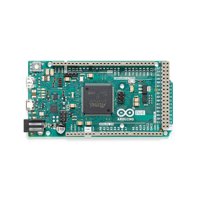
The board contains everything needed to support the microcontroller; simply connect it to a computer with a micro-USB cable or power it with an AC-to-DC adapter or battery to get started. The Due is compatible with all Arduino shields that work at 3.3V and are compliant with the 1.0 Arduino pinout.
The Due follows the 1.0 pinout:
TWI: SDA and SCL pins that are near to the AREF pin.
IOREF: allows an attached shield with the proper configuration to adapt to the voltage provided by the board. This enables shield compatibility with a 3.3V board like the Due and AVR-based boards which operate at 5V.
An unconnected pin, reserved for future use.
Specifications
Operating Voltage
3.3 V
Input Voltage
7-12 V
Digital I/O
54
Analog Input Pins
12
Analog Output Pins
2 (DAC)
Total DC Output Current on all I/O Lines
130 mA
DC Current per I/O Pin
20 mA
DC Current for 3.3 V Pin
800 mA
DC Current for 5 V Pin
800 mA
Flash Memory
512 KB all available for the user applications
SRAM
96 KB
Clock Speed
84 MHz
Length
101.52 mm
Width
53.3 mm
Weight
36 g
Please note: Unlike most Arduino boards, the Arduino Due board runs at 3.3V. The maximum voltage that the I/O pins can tolerate is 3.3V. Applying voltages higher than 3.3V to any I/O pin could damage the board.
The SparkFun Qwiic OpenLog is the smarter and better looking cousin to the extremely popular OpenLog but now we've ported the original serial based interface to I²C! Thanks to the added Qwiic connectors, you can daisy chain multiple I²C devices and log them all without taking up your serial port. The Qwiic OpenLog can store, or 'log', huge amounts of serial data and act as a black box of sorts to store all the data that your project generates, for scientific or debugging purposes. Utilizing our handy Qwiic system, no soldering is required to connect it to the rest of your system. However, we still have broken out 0.1'-spaced pins in case you prefer to use a breadboard. Like its predecessor, the SparkFun Qwiic OpenLog runs off of an onboard ATmega328, running at 16 MHz thanks to the onboard resonator. The ATmega328 has been sure to feature the Optiboot bootloader loaded, which allows the OpenLog to be compatible with the “Arduino Uno” board setting in the Arduino IDE. It is important to be aware that the Qwiic OpenLog draws approximately 2 mA-6 mA in idle (nothing to record) mode, however, during a full record the OpenLog can draw 20 mA to 23 mA depending on the microSD card being used. The Qwiic OpenLog also supports clock stretching, which means it performs even better than the original and will record data up to 20,000 bytes per second at 400 kHz. As the receive buffer fills up this OpenLog will hold the clock line, letting the master know that it is busy. Once the Qwiic OpenLog is finished with a task, it releases the clock thus allowing the data to continue flowing without corruption. For even better performance the OpenLog Artemis is the tool you need, featuring logging speeds up to 500000 bps. Features Continuous data logging at 20,000 bytes per second without corruption Compatible with high speed 400 kHz I²C Compatible with 64 MB to 32 GB microSD cards (FAT16 or FAT32) Preloaded Uno bootloader so upgrading the firmware is as easy as loading a new sketch Valid I²C Addresses: 0x08 to 0x77 2x Qwiic Connectors Downloads Schematic Eagle Files Hookup Guide Arduino Library GitHub
The Data Logging Carrier Board breaks out connections for I²C via a Qwiic connector or standard 0.1'-spaced PTH pins along with SPI and serial UART connections for logging data from peripheral devices using those communication protocols.
The Data Logging Carrier Board allows you to control power to both the Qwiic connector on the board and a dedicated 3.3 V power rail for non-Qwiic peripherals so you can pick and choose when to power the peripherals you are monitoring the data from. It also features a charging circuit for single-cell Lithium-ion batteries along with a separate RTC battery-backup circuit to maintain power to a real-time clock circuit on your Processor Board.
Features
M.2 MicroMod Connector
microSD socket
USB-C Connector
3.3 V 1 A Voltage Regulator
Qwiic Connector
Boot/Reset Buttons
RTC Backup Battery & Charge Circuit
Independent 3.3 V regulators for Qwiic bus and peripheral add-ons
Controlled by digital pins on Processor Board to enable low power sleep modes
Phillips #0 M2.5 x 3 mm screw included
Using the RFID Starter Kit
An Arduino board has now become ‘the’ basic component in the maker community. No longer is an introduction to the world of microcontrollers the preserve of the expert. When it comes to expanding the capabilities of the basic Arduino board however, the developer is still largely on his own. If you really want to build some innovative projects it’s often necessary to get down to component level. This can present many beginners with major problems. That is exactly where this book begins.
This book explains how a wide variety of practical projects can be built using items supplied in a single kit together with the Arduino board. This kit, called the 'RFID Starter Kit for Arduino' (SKU 17240) is not just limited to RFID applications but contains more than 30 components, devices and modules covering all areas of modern electronics.
In addition to more simple components such as LEDs and resistors there are also complex and sophisticated modules that employ the latest technology such as:
A humidity sensor
A multicolor LED
A large LED matrix with 64 points of light
A 4-character 7-segment LED display
An infra red remote-controller unit
A complete LC-display module
A servo
A stepper motor and controller module
A complete RFID reader module and security tag
On top of that you will get to build precise digital thermometers, hygrometers, exposure meters and various alarm systems. There are also practical devices and applications such as a fully automatic rain sensor, a sound-controlled remote control system, a multifunctional weather station and so much more.
All of the projects described can be built using the components supplied in the Elektor kit.
This e-book (pdf), a software-only follow up to the best-selling Elektor Visual Studio C# range of books, is aimed at Engineers, Scientists and Enthusiasts who want to learn about the C# language and development environment.
It covers steps from installation, the .NET framework and object oriented programming, through to more advanced concepts including database applications, threading and multi-tasking, internet/network communications and writing DLLs. The DirectX chapters also include video capture. The e-book concludes with several chapters on writing Android applications in C# using the Xamarin add-on.
This e-book is based on the Visual Studio 2015 development environment and latest C# additions including WPF applications, LINQ queries, Charts and new commands such as await and async. The latest Visual Studio debugging features (PerfTips, Diagnostic Tool window and IntellTrace) are covered. Finally, the Android chapters include GPS, E-mail and SMS applications.
Additionally, the e-book provides free on-line access to extensive, well-documented examples — in a try for yourself style — together with links to the author’s videos, guiding you through the necessary steps to get the expected results.
The State of Hollow State Audio in the Second Decade of the 21st Century
Vacuum-tube (or valve, depending upon which side of the pond you live on) technology spawned the Age of Electronics early in the 20th Century. Until the advent of solid-state electronics near mid-century, hollow-state devices were the only choice. But following the invention of the transistor (after their process fell to reasonable levels), within a couple of decades, the death of vacuum tubes was widely heralded. Yet here we are some five decades later, and hollow-state equipment is enjoying something of a comeback, especially in the music and high-end audio industries.
Many issues surround hollow-state audio:
Does it produce—as some claim—better sound? If so, is there science to back up these claims?
How do hollow-state circuits work?
How do you design hollow-state audio circuits?
If hollow-state equipment fails, how do you go about troubleshooting and repairing it?
Can we recreate some of the classic hollow-state audio devices for modern listening rooms and recording studios?
How can we intelligently modify hollow-state amplifiers to our taste?
These and other topics are covered in The State of Hollow State Audio.
Elektor GREEN and GOLD members can download their digital edition here.
Not a member yet? Click here.
CaptureCountAn Object Detector and Counter on the Raspberry Pi 5
Voltage Reference With Arduino Pro MiniLinearize and Calibrate Your Analog Inputs
FPGAs for BeginnersThe Path From MCU to FPGA Programming
Update: STM32 Wireless Innovation Design Contest 2024
Bluetooth LE With MAUIControl Apps for Android & Co.
Port-Expanding Breakout BoardIncrease the Number of I/Os on Your Dev Board
AI SpecialistMachine Learning with the Jetson Nano
2024: An AI OdysseyFirst Forays Into TensorFlow
262,144 Ways to Play The Game of LifeA Reader’s Project in Brief
From Life’s ExperienceThe Chinese Dragon
Get Your (Brushed DC) Motor Running!Sample Projects from the Elektor Motor Control Development Bundle
ESP32-RS-232 AdapterA Wireless Link for Classic Test Equipment
Starting Out in Electronics……More About Opamps
ESP Library Recommendations
Piezoelectric DevicesPeculiar Parts, the Series
A Smart Object CounterImage Recognition Made Easy with Edge Impulse
Resolve Your Trickiest Embedded Development Challenges
ESP32 TerminalA Handheld Device with a Touch-Capable Display
Getting Started With the Zephyr RTOSAs Powerful as It Is Hard to Master
Award-Winning EthicsA Dialog with CTO Alexander Gerfer of Würth Elektronik eiSos on Enabling Innovation and Mindful Behavior
Err-lectronicsCorrections, Updates, and Readers’ Letters
Infographics: Embedded and AI
Square Wave Generation BenchmarksExploring ESP32, Pico, and Other Microcontrollers