The Power Delivery Board uses a standalone controller to negotiate with the power adapters and switch to a higher voltage other than just 5V. This uses the same power adapter for different projects rather than relying on multiple power adapters to provide different output; it can deliver the board as part of SparkFun’s Qwiic connect system, so you won’t have to do any soldering to figure out how things are oriented.
The SparkFun Power Delivery Board takes advantage of the power delivery standard using a standalone controller from STMicroelectronics, the STUSB4500. The STUSB4500 is a USB power delivery controller that addresses sink devices. It implements a proprietary algorithm to negotiate a power delivery contract with a source (i.e. a power delivery wall wart or power adapter) without the need for an external microcontroller. However, you will need a microcontroller to configure the board. PDO profiles are configured in an integrated non-volatile memory. The controller does all the heavy lifting of power negotiation and provides an easy way to configure over I²C.
To configure the board, you will need an I²C bus. The Qwiic system makes it easy to connect the Power Delivery board to a microcontroller. Depending on your application, you can also connect to the I²C bus via the plated through SDA and SCL holes.
Features
Input and output voltage range of 5-20V
Output current up to 5A
Three configurable power delivery profiles
Auto-run Type-C™ and USB PD sink controller
Certified USB Type-C™ rev 1.2 and USB PD rev 2.0 (TID #1000133)
Integrated VBUS voltage monitoring
Integrated VBUS switch gate drivers (PMOS)
The SparkFun RedBoard Qwiic is an Arduino-compatible board that combines features of different Arduinos with the Qwiic Connect System.
Features
ATmega328 microcontroller with Optiboot Bootloader
R3 Shield Compatible
CH340C Serial-USB Converter
3.3 V to 5 V Voltage Level Jumper
A4 / A5 Jumpers
AP2112 Voltage Regulator
ISP Header
Input voltage: 7 V - 15 V
1 Qwiic Connector
16 MHz Clock Speed
32 k Flash Memory
All SMD Construction
Improved Reset Button
Plug a reader into the headers, use a Qwiic cable, scan your 125kHz ID tag, and the unique 32-bit ID will be shown on the screen. The unit comes with a read LED and buzzer, but don't worry, there is a jumper you can cut to disable the buzzer if you want. Utilizing SparkFun's handy Qwiic system, no soldering is required to connect it to the rest of your system. However, we still have broken out 0.1"-spaced pins if you prefer to use a breadboard.
Utilizing the onboard ATtiny84A, the Qwiic RFID takes the six byte ID tag of your 125kHz RFID card, attaches a timestamp to it, and puts it onto a stack that holds up to 20 unique RFID scans at a time. This information is easy to get at with some simple I²C commands.
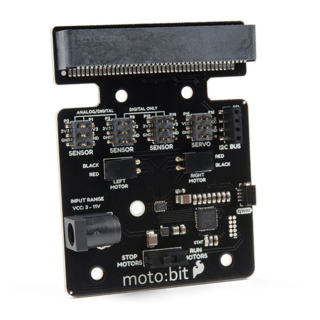
Onboard each moto:bit are multiple I/O pins, as well as a vertical Qwiic connector, capable of hooking up servos, sensors and other circuits. At the flip of the switch, you can get your micro:bit moving! The moto:bit connects to the micro:bit via an updated SMD, edge connector at the top of the board, making setup easy. This creates a handy way to swap out micro:bits for programming while still providing reliable connections to all of the different pins on the micro:bit. We have also included a basic barrel jack on the moto:bit that is capable of providing power to anything you connect to the carrier board. Features More reliable Edge connector for easy use with the micro:bit Full H-Bridge for control of two motors Control servo motors Vertical Qwiic Connector I²C port for extending functionality Power and battery management onboard for the micro:bit
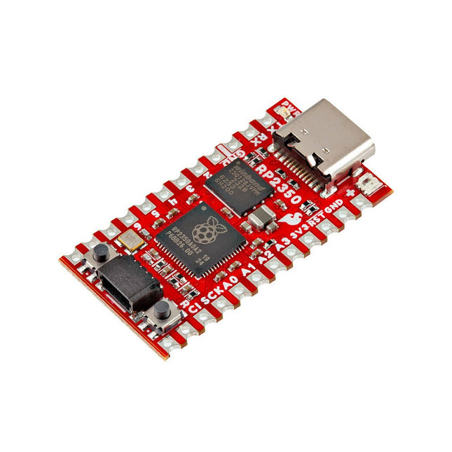
The SparkFun RP2350 Pro Micro provides a powerful development platform, built around the RP2350 microcontroller. This board uses the updated Pro Micro form factor. It includes a USB-C connector, Qwiic connector, WS2812B addressable RGB LED, Boot and Reset buttons, resettable PTC fuse, and PTH and castellated solder pads.
The RP2350 is a unique dual-core microcontroller with two ARM Cortex-M33 processors and two Hazard3 RISC-V processors, all running at up to 150 MHz! Now, this doesn't mean the RP2350 is a quad-core microcontroller. Instead, users can select which two processors to run on boot instead. You can run two processors of the same type or one of each. The RP2350 also features 520 kB SRAM in ten banks, a host of peripherals including two UARTs, two SPI and two I²C controllers, and a USB 1.1 controller for host and device support.
The Pro Micro also includes two expanded memory options: 16 MB of external Flash and 8 MB PSRAM connected to the RP2350's QSPI controller. The RP2350 Pro Micro works with C/C++ using the Pico SDK, MicroPython, and Arduino development environments.
Features
RP2350 Microcontroller
8 MB PSRAM
16 MB Flash
Supply Voltage
USB: 5 V
RAW: 5.3 V (max.)
Pro Micro Pinout
2x UART
1x SPI
10x GPIO (4 used for UART1 and UART0)
4x Analog
USB-C Connector
USB 1.1 Host/Device Support
Qwiic Connector
Buttons
Reset
Boot
LEDs
WS2812 Addressable RGB LED
Red Power LED
Dimensions: 33 x 17.8 mm
Downloads
Schematic
Eagle Files
Board Dimensions
Hookup Guide
RP2350 MicroPython Firmware (Beta 04)
SparkFun Pico SDK Library
Arduino Pico Arduino Core
Datasheet (RP2350)
Datasheet (APS6404L PSRAM)
RP2350 Product Brief
Raspberry Pi RP2350 Microcontroller Documentation
Qwiic Info Page
GitHub Repository
The SparkFun GPS-RTK2 raises the bar for high-precision GPS and is the latest in a line of powerful RTK boards featuring the ZED-F9P module from u-blox. The ZED-F9P is a top-of-the-line module for high accuracy GNSS and GPS location solutions, including RTK capable of 10 mm, three-dimensional accuracy. With this board, you will be able to know where your (or any object's) X, Y, and Z location is within roughly the width of your fingernail! The ZED-F9P is unique in that it is capable of both rover and base station operations. Utilizing our handy Qwiic system, no soldering is required to connect it to the rest of your system. However, we still have broken out 0.1"-spaced pins if you prefer to use a breadboard.
We've even included a rechargeable backup battery to keep the latest module configuration and satellite data available for up to two weeks. This battery helps 'warm-start' the module decreasing the time-to-first-fix dramatically. This module features a survey-in mode allowing the module to become a base station and produce RTCM 3.x correction data.
The number of configuration options of the ZED-F9P is incredible! Geofencing, variable I²C address, variable update rates, even the high precision RTK solution can be increased to 20 Hz. The GPS-RTK2 even has five communications ports which are all active simultaneously: USB-C (which enumerates as a COM port), UART1 (with 3.3 V TTL), UART2 for RTCM reception (with 3.3V TTL), I²C (via the two Qwiic connectors or broken out pins), and SPI.
Sparkfun has also written an extensive Arduino library for u-blox modules to easily read and control the GPS-RTK2 over the Qwiic Connect System. Leave NMEA behind! Start using a much lighter weight binary interface and give your microcontroller (and its one serial port) a break. The SparkFun Arduino library shows how to read latitude, longitude, even heading and speed over I²C without the need for constant serial polling.
Features
Concurrent reception of GPS, GLONASS, Galileo and BeiDou
Receives both L1C/A and L2C bands
Voltage: 5 V or 3.3 V, but all logic is 3.3 V
Current: 68 mA - 130 mA (varies with constellations and tracking state)
Time to First Fix: 25 s (cold), 2 s (hot)
Max Navigation Rate:
PVT (basic location over UBX binary protocol) - 25 Hz
RTK - 20 Hz
Raw - 25 Hz
Horizontal Position Accuracy:
2.5 m without RTK
0.010 m with RTK
Max Altitude: 50k m
Max Velocity: 500 m/s
2x Qwiic Connectors
Dimensions: 43.5 x 43.2 mm
Weight: 6.8 g
The MLX90640 SparkFun IR Array Breakout features a 32×24 array of thermopile sensors generating, in essence, a low resolution thermal imaging camera. With this breakout you can observe surface temperatures from a decent distance away with an accuracy of ±1.5°C (best case). This board communicates via I²C using the Qwiic system developed by Sparkfun, which makes it easier to operate the breakout. However, there are still 0.1'-spaced pins in case you favour using a breadboard.
The SparkFun Qwiic connect system is an ecosystem of I²C sensors, actuators, shields and cables that make prototyping faster and helps you avoid errors. All Qwiic-enabled boards use a common 1 mm pitch, 4-pin JST connector. This reduces the amount of required PCB space, and polarized connections help you connect everything correctly.
This specific IR Array Breakout provides a 110°×75° field of view with a temperature measurement range of -40~300°C. The MLX90640 IR Array has pull up resistors attached to the I²C bus; both can be removed by cutting the traces on the corresponding jumpers on the back of the board. Please be aware that the MLX90640 requires complex calculations by the host platform so a regular Arduino Uno (or equivalent) doesn't have enough RAM or flash to complete the complex computations required to turn the raw pixel data into temperature data. You will need a microcontroller with 20,000 bytes or more of RAM.
The RP2040 utilizes dual ARM Cortex-M0+ processors (up to 133MHz):
264kB of embedded SRAM in six banks
6 dedicated IO for SPI Flash (supporting XIP)
30 multifunction GPIO:
Dedicated hardware for commonly used peripherals
Programmable IO for extended peripheral support
Four 12-bit ADC channels with internal temperature sensor (up to 0.5 MSa/s)
USB 1.1 Host/Device functionality
The RP2040 is supported with C/C++ and MicroPython cross-platform development environments, including easy access to runtime debugging. It has a UF2 boot and floating-point routines baked into the chip. The built-in USB can act as both device and host. It has two symmetric cores and high internal bandwidth, making it useful for signal processing and video. While the chip has a large internal RAM, the board includes an additional external flash chip.
Features
Dual Cortex M0+ processors, up to 133 MHz
264 kB of embedded SRAM in 6 banks
6 dedicated IO for QSPI flash, supporting execute in place (XIP)
30 programmable IO for extended peripheral support
SWD interface
Timer with 4 alarms
Real-time counter (RTC)
USB 1.1 Host/Device functionality
Supported programming languages
MicroPython
C/C++
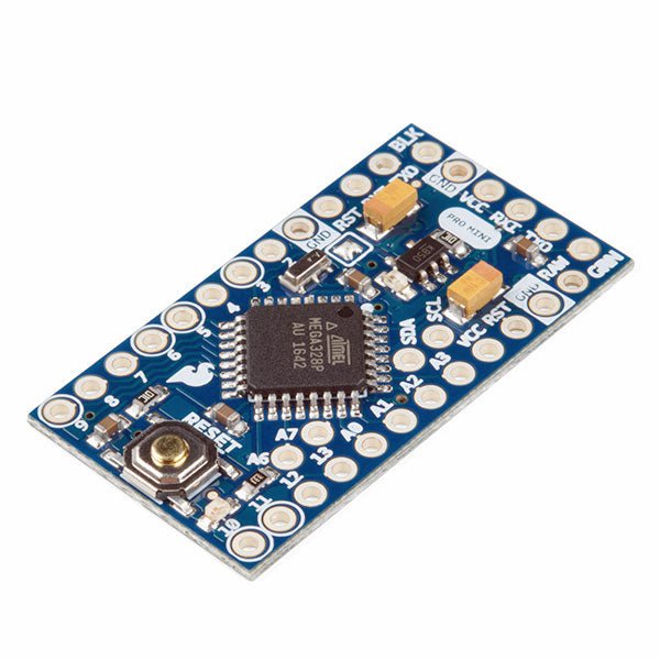
The Arduino Pro Mini is a microcontroller board based on the ATmega328P.
It has 14 digital input/output pins (of which 6 can be used as PWM outputs), 6 analog inputs, an on-board resonator, a reset button, and holes for mounting pin headers. A six pin header can be connected to an FTDI cable or SparkFun breakout board to provide USB power and communication to the board.
The Arduino Pro Mini is intended for semi-permanent installation in objects or exhibitions. The board comes without pre-mounted headers, allowing the use of various types of connectors or direct soldering of wires. The pin layout is compatible with the Arduino Mini.
The Arduino Pro Mini was designed and is manufactured by SparkFun Electronics.
Specifications
Microcontroller
ATmega328P
Board Power Supply
5-12 V
Circuit Operating Voltage
5 V
Digital I/O Pins
14
PWM Pins
6
UART
1
SPI
1
I²C
1
Analog Input Pins
6
External Interrupts
2
DC Current per I/O Pin
40 mA
Flash Memory
32 KB of which 2 KB used by bootloader
SRAM
2 KB
EEPROM
1 KB
Clock Speed
16 MHz
Dimensions
18 x 33.3 mm (0.7 x 1.3")
Downloads
Eagle files
Schematics
Reinforcing its commitment to widening the accessibility to and innovation in the area of deep learning, NVIDIA has created a free, self-paced, online Deep Learning Institute (DLI) course, “Getting Started on AI with Jetson Nano.” The course's goal is to build foundational skills to enable anyone to get creative with the Jetson Developer Kit. Please be aware that this kit is for those who already own a Jetson Nano Developer Kit and want to join the DLI Course. A Jetson Nano is not included in this kit.
Included in this kit is everything you will need to get started in the “Getting Started on AI with Jetson Nano” (except for a Jetson Nano, of course), and you will learn how to
Set up your Jetson Nano and camera
Collect image data for classification models
Annotate image data for regression models
Train a neural network on your data to create your own models
Run inference on the Jetson Nano with the models you create
The NVIDIA Deep Learning Institute offers hands-on training in AI and accelerated computing to solve real-world problems. Developers, data scientists, researchers, and students can get practical experience powered by GPUs in the cloud and earn a competency certificate to support professional growth. They offer self-paced, online training for individuals, instructor-led workshops for teams, and downloadable course materials for university educators.
Included
32 GB microSD Card
Logitech C270 Webcam
Power Supply 5 V, 4 A
USB Cable - microB (Reversible)
2-Pin Jumper
Please note: Jetson Nano Developer Kit not included.
This module includes an integrated trace antenna, fits the IC to an FCC-approved footprint, and includes decoupling and timing mechanisms that would need to be designed into a circuit using the bare nRF52840 IC. The Bluetooth transceiver included on the nRF52840 boasts a BT 5.1 stack. It supports Bluetooth 5, Bluetooth mesh, IEEE 802.15.4 (Zigbee & Thread) and 2.4Ghz RF wireless protocols (including Nordic's proprietary RF protocol) allowing you to pick which option works best for your application.
Features
ARM Cortex-M4 CPU with a floating-point unit (FPU)
1MB internal Flash -- For all of your program, SoftDevice, and file-storage needs!
256kB internal RAM -- For your stack and heap storage.
Integrated 2.4GHz radio with support for:
Bluetooth Low Energy (BLE) -- With peripheral and/or central BLE device support
Bluetooth 5 -- Mesh Bluetooth!
ANT -- If you want to turn the device into a heart-rate or exercise monitor.
Nordic's proprietary RF protocol -- If you want to communicate, securely, with other Nordic devices.
Every I/O peripheral you could need.
USB -- Turn your nRF52840 into a USB mass-storage device, use a CDC (USB serial) interface, and more.
UART -- Serial interfaces with support for hardware flow-control if desired.
I²C -- Everyone's favourite 2-wire bi-directional bus interface
SPI -- If you prefer the 3+-wire serial interface
Analogue-to-digital converters (ADC) -- Eight pins on the nRF52840 Mini Breakout support analogue inputs
PWM -- Timer support on any pin means PWM support for driving LEDs or servo motors.
Real-time clock (RTC) -- Keep close track of seconds and milliseconds, also supports timed deep-sleep features.
Three UARTs
Primary tied to USB interface. Two hardware UARTs.
Two I²C Buses
Two SPI Buses
Secondary SPI Bus primarily used for Flash IC.
PDM Audio Processing
Two Analog Inputs
Two Dedicated Digital I/O Pins
Two Dedicated PWM Pins
Eleven General Purpose I/O Pins
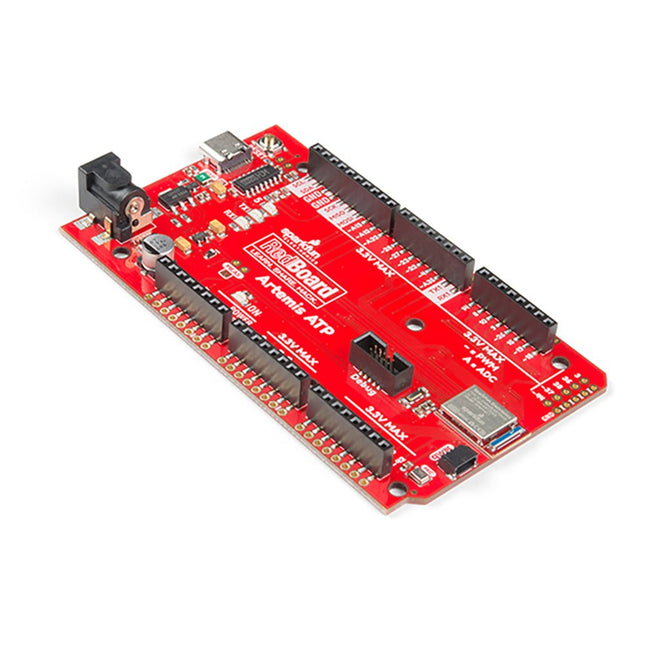
What's with the silkscreen labels? They're all over the place. We decided to label the pins as they are assigned on the Apollo3 IC itself. This makes finding the pin with the function you desire a lot easier. Have a look at the full pin map from the Apollo3 datasheet. If you really need to test out the 4-bit SPI functionality of the Artemis, you're going to need to access pins 4, 22, 23, and 26. Need to try out the differential ADC port 1? Pins 14 and 15. The RedBoard Artemis ATP will allow you to flex the impressive capabilities of the Artemis module.
The RedBoard Artemis ATP has the improved power conditioning and USB to serial that we've refined over the years on our RedBoard line of products. A modern USB-C connector makes programming easy. A Qwiic connector makes I²C easy. The ATP is fully compatible with SparkFun's Arduino core and can be programmed easily under the Arduino IDE. We've exposed the JTAG connector for more advanced users who prefer to use the power and speed of professional tools. If you need a lot of a GPIO with a simple program, ready to go to the market module, the ATP is the fix you need. We've added a digital MEMS microphone for folks wanting to experiment with always-on voice commands with TensorFlow and machine learning. We've even added a convenient jumper to measure current consumption for low power testing.
With 1 MB flash and 384k RAM, you'll have plenty of room for your sketches. The Artemis module runs at 48 MHz with a 96 MHz turbo mode available and with Bluetooth to boot!
Features
Arduino Mega Footprint
1M Flash / 384k RAM
48MHz / 96MHz turbo available
6uA/MHz (operates less than 5mW at full operation)
48 GPIO - all interrupt capable
31 PWM channels
Built-in BLE radio
10 ADC channels with 14-bit precision with up to 2.67 million samples per second effective continuous, multi-slot sampling rate
2 channel differential ADC
2 UARTs
6 I²C buses
6 SPI buses
2/4/8-bit SPI bus
PDM interface
I²S Interface
Secure 'Smart Card' interface
Qwiic Connector