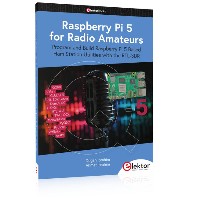
Program and Build Raspberry Pi 5 Based Ham Station Utilities with the RTL-SDR
The RTL-SDR devices (V3 and V4) have gained popularity among radio amateurs because of their very low cost and rich features. A basic system may consist of a USB based RTL-SDR device (dongle) with a suitable antenna, a Raspberry Pi 5 computer, a USB based external audio input-output adapter, and software installed on the Raspberry Pi 5 computer. With such a modest setup, it is possible to receive signals from around 24 MHz to over 1.7 GHz.
This book is aimed at amateur radio enthusiasts and electronic engineering students, as well as at anyone interested in learning to use the Raspberry Pi 5 to build electronic projects. The book is suitable for both beginners through experienced readers. Some knowledge of the Python programming language is required to understand and eventually modify the projects given in the book. A block diagram, a circuit diagram, and a complete Python program listing is given for each project, alongside a comprehensive description.
The following popular RTL-SDR programs are discussed in detail, aided by step-by-step installation guides for practical use on a Raspberry Pi 5:
SimpleFM
GQRX
SDR++
CubicSDR
RTL-SDR Server
Dump1090
FLDIGI
Quick
RTL_433
aldo
xcwcp
GPredict
TWCLOCK
CQRLOG
klog
Morse2Ascii
PyQSO
Welle.io
Ham Clock
CHIRP
xastir
qsstv
flrig
XyGrib
FreeDV
Qtel (EchoLink)
XDX (DX-Cluster)
WSJT-X
The application of the Python programming language on the latest Raspberry Pi 5 platform precludes the use of the programs in the book from working on older versions of Raspberry Pi computers.
Practical Guide to Modular RF Design
Build Your Own Software-Defined Radio combines RF circuitry with hardware programming and PC-based signal processing. The e-book presents a modular approach to building a complete SDR system using RF Bricks – from the mechanical framework and RF modules to measurement tools, PC software, and FPGA implementations. Practical explanations guide readers through real signal paths, construction steps, and measurement routines, linking hardware and software into a flexible SDR platform.
Key topics include:
Mechanical setup: RF Brick template, chassis, and 19-inch module carrier
Bridges: USB isolator, I²C level shifter, I²C power switch, and practical examples
Signal-chain design with RF Bricks: antennas, band filters, NanoVNA work, preamplifiers, PLLs, demodulators, direct-conversion chains, multiband options, and narrowband bricks
RF measurement Bricks: single- and dual-tone sources, NPR methods, noise generators, notch filters, broadband amplifiers, and impedance bridges
Useful accessories: ATU-100 tuner, X-Phase QRM eliminator, and firmware notes
PC host software: SoapyAudio adjustments, GQRX, SDR++, and added functionality
GnuRadio elements: control blocks, SSB demodulation, GUI components, messaging, and filter handling
FPGA-based SDR: VHDL, toolchains, ADC/DAC blocks, oversampling, and a complete SSB/CW signal chain
With its modular structure and detailed working examples, this e-book offers a practical path to building and extending modern SDR systems.
Downloads
Software
Getting started with the world’s best open-source PCB tool
The latest iteration of KiCad, the world’s best free-to-use Printed Circuit Board tool, is packed with features usually found only in expensive commercial CAD tools. This modern, cross-platform application suite built around schematic and design editors, with auxiliary applications is a stable and mature PCB tool. KiCad 8 is a perfect fit for electronic engineers and makers.
Here are the most significant improvements and features in KiCad 8, both over and under the hood:
Modern user interface, completely redesigned from earlier versions
Improved and customizable electrical and design rule checkers
Theme editor allowing you to customize KiCad on your screen
Ability to import projects from Eagle, CADSTART, and more
Python scripting API
Improved integrated SPICE circuit simulator
Multi-sheet schematics
Filters define selectable elements
Enhanced interactive router helps you draw single tracks and differential pairs with precision
New or enhanced tools to draw tracks, measure distances, tune track lengths, etc.
Advanced interactive router
Built-in bill of materials generator
Realistic ray-tracing capable 3D viewer
Customizable teardrops
Plug-in manager for quick installation of themes, libraries and functionalities such as autorouters and BOM generators
This book will teach you to use KiCad through a practical approach. It will help you become productive quickly and start designing your own boards. Example projects illustrate the basic features of KiCad, even if you have no prior knowledge of PCB design.
The author describes the entire workflow from schematic entry to the intricacies of finalizing the files for PCB production and offers sound guidance on the process. Further full-fledged projects, of incremental difficulty, will be presented in a second book, together with a variety of advanced recipes.
Practical Low-Cost Methods for Reliable PCB Production
This book explains how to carry out reliable SMD assembly using affordable tools and small-scale equipment. It follows the complete workflow step by step, including tool selection, solder paste handling, stencil use, component placement, reflow methods, inspection, and rework.
The focus is on bench-level and small-lab production rather than industrial assembly lines. It shows practical methods for building single and double-sided SMD boards with repeatable results.
Topics include solder paste and flux, temperature profiles, hot air and hotplate techniques, small reflow ovens, inspection methods, and defect correction. Checklists and example workflows are included to help reduce errors and improve consistency.
Key features:
Tools and supplies for SMD assembly and rework
Solder paste types, storage, and handling
Stencils and paste application methods
Pick and place workflow and component orientation
Temperature profiles and reflow methods
Hot air, hotplate, and reflow oven processes
Inspection and quality control
Common defects such as tombstoning and solder bridges
Practical rework and component replacement
Bench-level professional workflows and checklists
This book is designed as a practical bench reference for anyone who wants to assemble and troubleshoot their own SMD boards with reliable results.
Programming and Projects for the Minima and WiFi
Based on the low-cost 8-bit ATmega328P processor, the Arduino Uno R3 board is likely to score as the most popular Arduino family member, and this workhorse has been with us for many years. Eleven years later, the long-overdue successor, the Arduino Uno R4, was released. It is built around a 48 MHz, 32-bit Arm Cortex-M4 microcontroller and provides significantly expanded SRAM and Flash memory. Additionally, a higher-precision ADC and a new DAC are added to the design. The Uno R4 board also supports the CAN Bus with an interface.
Two versions of the board are available: Uno R4 Minima, and Uno R4 WiFi. This book is about using these new boards to develop many different and interesting projects with just a handful of parts and external modules. All projects described in the book have been fully tested on the Uno R4 Minima or the Uno R4 WiFi board, as appropriate.
The project topics include the reading, control, and driving of many components and modules in the kit as well as on the relevant Uno R4 board, including
LEDs
7-segment displays (using timer interrupts)
LCDs
Sensors
RFID Reader
4x4 Keypad
Real-time clock (RTC)
Joystick
8×8 LED matrix
Motors
DAC (Digital-to-analog converter)
LED matrix
WiFi connectivity
Serial UART
CAN bus
Infrared controller and receiver
Simulators
… all in creative and educational ways with the project operation and associated software explained in great detail.
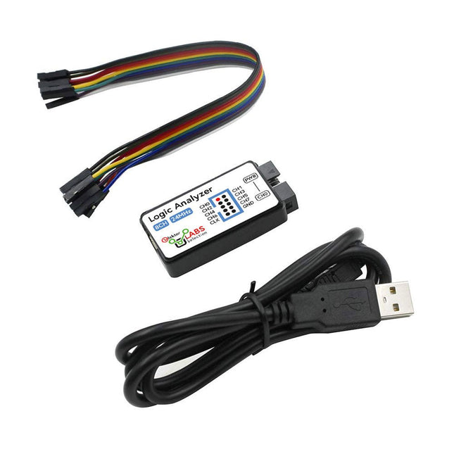
This USB Logic Analyzer is an 8-channel logic analyzer with each input dual purposed for analog data recording. It is perfect for debugging and analyzing signals like I²C, UART, SPI, CAN and 1-Wire. It operates by sampling a digital input connected to a device under test (DUT) at a high sample rate. The connection to the PC is via USB.
Specifications
Channels
8 digital channels
Maximum sampling rate
24 MHz
Maximum input voltage
0~5 V
Operating temperature
0~70°C
Input impedance
1 MΩ || 10 pF
Supported protocols
I²C, SPI, UART, CAN, 1-Wire, etc.
PC connection
USB
Dimensions
55 x 28 x 14 mm
Included
USB Logic Analyzer (8-ch, 24 MHz)
USB Cable
Jumper Wire Ribbon Cable
Downloads
Software
The FNIRSI SWM-20 handheld spot welder is a high-efficiency, user-friendly, and easy-to-carry welding tool. It features dual-pulse spot welding technology, ensuring more stable and reliable welds, and also includes a convenient power bank function.
Equipped with a 2.4-inch HD display, the SWM-20 offers clear and intuitive operation. Its rotary encoder knob allows users to adjust parameters quickly and precisely, making it easy to set the required welding settings and improving the overall user experience.
Features
2-in-1: Spot Welder & 5000 mAh Power Bank
1200 A High-Power Output for Strong, Reliable Welds
Dual-Pulse Technology for Cleaner & More Stable Welding
Dual A-Grade Batteries with 8 Safety Protections
0.1–0.5 mm Multi-Material Welding Capability
10,000+ Precision Adjustment Levels for Professional Control
2.4-inch TFT Display with Real-Time Data Monitoring
Specifications
Max Welding Current
1200 A
Battery Capacity
5000 mAh
Charging
5 V/2.1 A
Discharging
5 V/2.1 A
Welding Materials
Nickel, Iron, Stainless Steel
Welding Thickness
0.1‒0.5 mm
Level
4 Preset Combination Levels
Dimensions
13.3 x 8.8 x 3.2 cm
Weight
850 g
Included
1x FNIRSI SWM-20 Spot Welder
2x Welding Pens
2x Replacement Tips
1x Nickel Strip
1x USB-C Cable
1x Manual
Downloads
Manual
Learn to Build Intelligent Embedded Systems
Build smarter embedded systems with Arduino UNO Q. This book gives you the tools, knowledge, and confidence to turn ideas into intelligent, working solutions using the Arduino UNO Q platform. Discover how to build intelligent embedded systems with the Arduino UNO Q and AI.
Unlock the full potential of the Arduino UNO Q, a next-generation platform that combines the real-time power of the STM32U585 microcontroller with the flexibility of a Qualcomm Dragonwing QRB2210 microprocessor.
Learn how to rapidly prototype real-world applications using the Arduino IDE for low-level embedded control and Python in Arduino App Lab for high-level development.
Build confidence through hands-on projects that guide you step by step from basic board features to complete working systems.
Explore ready-to-use, AI based Arduino App Lab examples and see how they can jump-start your development and reduce time to deployment.
Step into the world of Edge AI with a clear, practical introduction to Edge Impulse Studio—no prior AI experience required.
Follow a complete, real-world workflow to create a Keyword Spotting AI application, covering data collection, model training, optimization, and on-device inference using the Edge Impulse Studio.
Bridge the gap between embedded systems and machine learning and learn how to bring intelligence directly onto your hardware.
Perfect for embedded engineers, educators, students, and makers looking to stay ahead in AI-enabled product development.
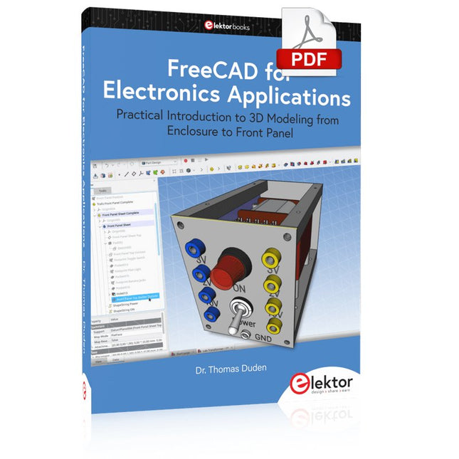
Practical Introduction to 3D Modeling from Enclosure to Front Panel
Embedding a vintage component, creating a professional looking home for a circuit board, or even designing a complex apparatus complete with a chassis – these and many other challenges turn into a stimulating pleasure with FreeCAD. Once you have internalized the basic processes, there are virtually no limits to your imagination.
Starting to use a new software is never straightforward – especially with a tool as versatile as FreeCAD. Manageable, but at the same time easily usable individual components provide the starting point in this book. Putting these components together later results in assemblies.
In the FreeCAD universe, a workable trajectory is demonstrated. The described procedure is illustrative so the examples are easily applied to custom tasks. The devices were made by the author and illustrated with photos.
Creating a 3D design is requiring some effort but the initial investment pays off soon. Besides the impressive spatial representation of the projects, the extracted drawings yield a solid base for documentation and production. Extended FreeCAD capabilities like the unfolding of sheet metal parts enormously add to efficiency and pushes models forward into practical assembly.
Soon you will definitely not want to do without FreeCAD!
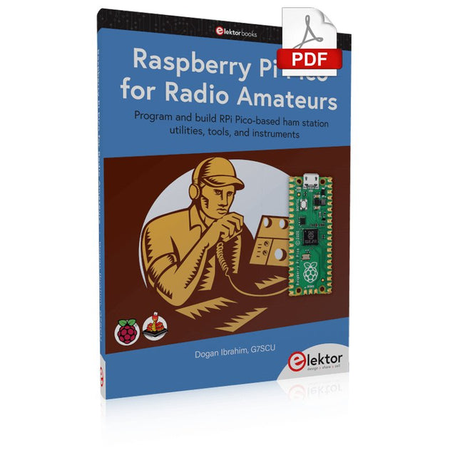
Program and build RPi Pico-based ham station utilities, tools, and instruments
Although much classical HF and mobile equipment is still in use by large numbers of amateurs, the use of computers and digital techniques has now become very popular among amateur radio operators. Nowadays, anyone can purchase a €5 Raspberry Pi Pico microcontroller board and develop many amateur radio projects using the “Pico” and some external components. This book is aimed at amateur radio enthusiasts, Electronic Engineering students, and anyone interested in learning to use the Raspberry Pi Pico to shape their electronic projects. The book is suitable for beginners in electronics as well as for those with wide experience.
Step-by-step installation of the MicroPython programming environment is described. Some knowledge of the Python programming language is helpful to be able to comprehend and modify the projects given in the book. The book introduces the Raspberry Pi Pico and gives examples of many general-purpose, software-only projects that familiarize the reader with the Python programming language. In addition to the software-only projects tailored to the amateur radio operator, Chapter 6 in particular presents over 36 hardware-based projects for “hams”, including:
Station mains power on/off control
Radio station clock
GPS based station geographical coordinates
Radio station temperature and humidity
Various waveform generation methods using software and hardware (DDS)
Frequency counter
Voltmeter / ammeter / ohmmeter / capacitance meter
RF meter and RF attenuators
Morse code exercisers
RadioStation Click board
Raspberry Pi Pico based FM radio
Using Bluetooth and Wi-Fi with Raspberry Pi Pico
Radio station security with RFID
Audio amplifier module with rotary encoder volume control
Morse decoder
Using the FS1000A TX-RX modules to communicate with Arduino
From SRPP and Mu-Follower to OTL Designs
Tube amplifiers suffer from distortion. Fortunately, circuits such as the SRPP amplifier, mu-follower, and beta-follower produce minimal distortion even at output voltages of 50 to 100 Vpeak.
These designs are often published with errors. Without a sound understanding of the theory, it is easy to arrive at a flawed design.
In the first section of this book, we investigate the origin of distortion, while in the second we investigate the design of and SRPP and a mu-follower.
On the internet we can find the most exotic designs. Evaluating them teaches us that these designs often make matters worse rather than better. In the chapter on incorrect SRPPs and mu-followers, we sometimes see bizarre and misguided designs where using a simple single-triode amplifier would perform much better.
Push-pull output stages also exist. A great number of them are examined, and their similarity to the SRPP is discussed. This is done especially with the help of the theory behind the OTL based on the ‘mother’ of all OTLs, the Philips HF303.
Finally, attention is given to frequency characteristics and technical matters such as the supply voltage and the filament power supply.
To illustrate these points, there are a few designs covering the subjects discussed.
This book presents much new theory that has not been published before. It is often an eye-opener, showing that many things have a beautiful and unexpected simplicity.
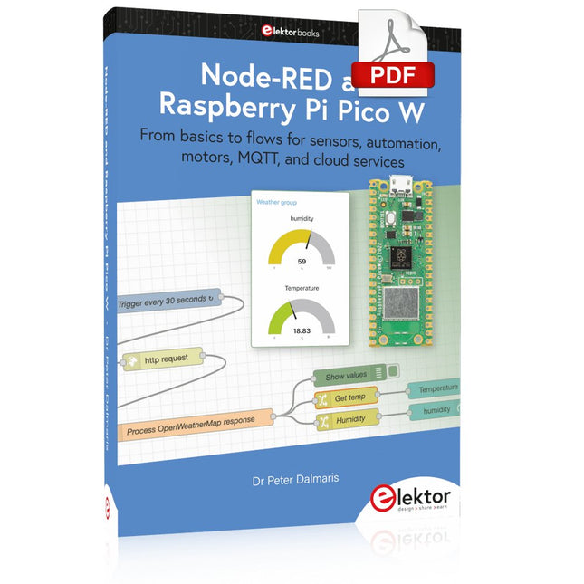
From basics to flows for sensors, automation, motors, MQTT, and cloud services
This book is a learning guide and a reference. Use it to learn Node-RED, Raspberry Pi Pico W, and MicroPython, and add these state-of-the-art tools to your technology toolkit. It will introduce you to virtual machines, Docker, and MySQL in support of IoT projects based on Node-RED and the Raspberry Pi Pico W.
This book combines several elements into a platform that powers the development of modern Internet of Things applications. These elements are a flow-based server, a WiFi-enabled microcontroller, a high-level programming language, and a deployment technology. Combining these elements gives you the tools you need to create automation systems at any scale. From home automation to industrial automation, this book will help you get started.
Node-RED is an open-source flow-based development tool that makes it easy to wire together devices, APIs, and online services. Drag and drop nodes to create a flowchart that turns on your lights at sunset or sends you an email when a sensor detects movement. Raspberry Pi Pico W is a version of the Raspberry Pi Pico with added 802.11n Wi-Fi capability. It is an ideal device for physical computing tasks and an excellent match to the Node-RED.
Quick book facts
Project-based learning approach.
Assumes no prior knowledge of flow-based programming tools.
Learn to use essential infrastructure tools in your projects, such as virtual machines, Docker, MySQL and useful web APIs such as Google Sheets and OpenWeatherMap.
Dozens of mini-projects supported by photographs, wiring schematics, and source code. Get these from the book GitHub repository.
Step-by-step instructions on everything.
All experiments are based on the Raspberry Pi Pico W. A Wi-Fi network is required for all projects.
Hardware (including the Raspberry Pi Pico W) is available as a kit.
Downloads
GitHub
TINA Design Suite is a professional, powerful and affordable circuit simulator. It is a circuit designer and PCB design software package for analysing, designing, and real-time testing of analogue, digital, IBIS, VHDL, Verilog, Verilog AMS, SystemC, MCU, and mixed electronic circuits and their PCB layouts.
In this book, top-selling Elektor author, Prof. Dr. Dogan Ibrahim aims to teach the design and analysis of electrical and electronic circuits and develop PCB boards using both TINA and TINACloud. The book is aimed at electrical/electronic engineers, undergraduate electronic/electrical engineering students at technical colleges and universities, postgraduate and research students, teachers, and hobbyists. Many tested and working simulation examples are provided covering most fields of analogue and digital electrical/electronic engineering. These include AC and DC circuits, diodes, zener diodes, transistor circuits, operational amplifiers, ladder diagrams, 3-phase circuits, mutual inductance, rectifier circuits, oscillators, active and passive filter circuits, digital logic, VHDL, MCUs, switch-mode power supplies, PCB design, Fourier series, and spectrum. Readers do not need to have any programming experience unless they wish to simulate complex MCU circuits.
Program, build, and master over 60 projects with Python
The Raspberry Pi 5 is the latest single-board computer from the Raspberry Pi Foundation. It can be used in many applications, such as in audio and video media centers, as a desktop computer, in industrial controllers, robotics, and in many domestic and commercial applications. In addition to the well-established features found in other Raspberry Pi computers, the Raspberry Pi 5 offers Wi-Fi and Bluetooth (classic and BLE), which makes it a perfect match for IoT as well as in remote and Internet-based control and monitoring applications. It is now possible to develop many real-time projects such as audio digital signal processing, real-time digital filtering, real-time digital control and monitoring, and many other real-time operations using this tiny powerhouse.
The book starts with an introduction to the Raspberry Pi 5 computer and covers the important topics of accessing the computer locally and remotely. Use of the console language commands as well as accessing and using the desktop GUI are described with working examples. The remaining parts of the book cover many Raspberry Pi 5-based hardware projects using components and devices such as
LEDs and buzzers
LCDs
Ultrasonic sensors
Temperature and atmospheric pressure sensors
The Sense HAT
Camera modules
Example projects are given using Wi-Fi and Bluetooth modules to send and receive data from smartphones and PCs, and sending real-time temperature and atmospheric pressure data to the cloud.
All projects given in the book have been fully tested for correct operation. Only basic programming and electronics experience are required to follow the projects. Brief descriptions, block diagrams, detailed circuit diagrams, and full Python program listings are given for all projects described.
With the availability of free and open source C/C++ compilers today, you might wonder why someone would be interested in assembler language. What is so compelling about the RISC-V Instruction Set Architecture (ISA)? How does RISC-V differ from existing architectures? And most importantly, how do we gain experience with the RISC-V without a major investment? Is there affordable hardware available?
The availability of the Espressif ESP32-C3 chip provides a way to get hands-on experience with RISC-V. The open sourced QEMU emulator adds a 64-bit experience in RISC-V under Linux. These are just two ways for the student and enthusiast alike to explore RISC-V in this book.
The projects in this book are boiled down to the barest essentials to keep the assembly language concepts clear and simple. In this manner you will have “aha!” moments rather than puzzling about something difficult. The focus in this book is about learning how to write RISC-V assembly language code without getting bogged down. As you work your way through this tutorial, you’ll build up small demonstration programs to be run and tested. Often the result is some simple printed messages to prove a concept. Once you’ve mastered these basic concepts, you will be well equipped to apply assembly language in larger projects.
Mastering Surface Mount Technology takes you on a crash course in techniques, tips and know-how to successfully introduce surface mount technology in your workflow. Even if you are on a budget you too can jumpstart your designs with advanced fine pitch parts.
Besides explaining methodology and equipment, attention is given to SMT parts technologies and soldering methods. In a step by step way, several projects introduce you to handling surface mount parts and the required skills to successfully build SMT assemblies. Many practical tips and tricks are disclosed that bring surface mount technology into everyone's reach without breaking the bank.
DEAL: Order the HackRF Pro now and get the new e-book "SDR with HackRF One & HackRF Pro" worth €20 for FREE!
HackRF Pro is latest Software Defined Radio (SDR) from Great Scott Gadgets and the powerful successor to the legendary HackRF One. With a frequency range from 100 kHz to 6 GHz, it covers an enormous spectrum for transmitting and receiving radio signals.
Designed as an open-source hardware platform, the HackRF Pro is the ideal tool for analyzing and developing modern wireless technologies. It can be used flexibly as a USB peripheral or programmed for standalone operation.
Specifications
Frequency: 100 kHz to 6 GHz
Adjustable from 0 Hz to 7.1 GHz
Half-duplex transceiver
Up to 20 million samples per second
8-bit quadrature samples (8-bit I and 8-bit Q)
Compatible with GNU Radio, SDR#, and more
Software-configurable RX and TX gain and baseband filter
Software-controlled RF port power (50 mA at 3.3 V)
SMA RF connector
SMA clock input and output for synchronization and triggering
Convenient buttons for programming
Internal pin headers for expansion
High-Speed USB 2.0 with USB-C connector
USB-powered
Open source hardware
Compared to its predecessor, HackRF Pro offers a variety of new features, including:
Wider operating frequency range
Improved RF performance with flatter frequency response
USB-C connector
Built-in TCXO crystal oscillator for superior timing stability
Logic upgrade from a CPLD to a power-efficient FPGA
Elimination of the DC spike
Extended-precision mode with 16-bit samples for low sample rates (typical ENOB: 9-11)
Half-precision mode with 4-bit samples at up to 40 Msps
More RAM and flash memory for custom firmware
Installed shielding around the radio section
Trigger input and output accessible through clock connectors
Cutout in the PCB provides space for future add-ons
Improved power management
Enhanced RF port protection
Facility to hardware-disable transmit mode
Full Compatibility: Thanks to its proven architecture, existing software for the HackRF One can also be used directly with the HackRF Pro. The HackRF Pro offers seamless backward compatibility while significantly increasing performance.
Note: An antenna is not included. We recommend the ANT500 for the best experience.
Included
HackRF Pro SDR with plastic enclosure
NEW e-book: SDR with HackRF One & HackRF Pro (normal price: €20)
Downloads
Documentation
GitHub
Most people are increasingly confronted with the applications of Artificial Intelligence (AI). Music or video ratings, navigation systems, shopping advice, etc. are based on methods that can be attributed to this field.
The term Artificial Intelligence was coined in 1956 at an international conference known as the Dartmouth Summer Research Project. One basic approach was to model the functioning of the human brain and to construct advanced computer systems based on this. Soon it should be clear how the human mind works. Transferring it to a machine was considered only a small step. This notion proved to be a bit too optimistic. Nevertheless, the progress of modern AI, or rather its subspecialty called Machine Learning (ML), can no longer be denied.
In this book, several different systems will be used to get to know the methods of machine learning in more detail. In addition to the PC, both the Raspberry Pi and the Maixduino will demonstrate their capabilities in the individual projects. In addition to applications such as object and facial recognition, practical systems such as bottle detectors, person counters, or a “talking eye” will also be created.
The latter is capable of acoustically describing objects or faces that are detected automatically. For example, if a vehicle is in the field of view of the connected camera, the information 'I see a car!' is output via electronically generated speech. Such devices are highly interesting examples of how, for example, blind or severely visually impaired people can also benefit from AI systems.
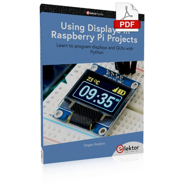
Learn to program displays and GUIs with Python
This book is about Raspberry Pi 4 display projects. The book starts by explaining how to install the latest Raspbian operating system on an SD card, and how to configure and use the GPIO ports.
The core of the book explains the following topics in simple terms with fully tested and working example projects:
Simple LED projects
Bar graph LED projects
Matrix LED projects
Bitmap LED projects
LED strips
LCDs
OLED displays
E-paper displays
TFT displays
7-inch touch screen
GUI Programming with Tkinder
One unique feature of this book is that it covers almost all types of display that readers will need to use in their Raspberry Pi based projects. The operation of each project is fully given, including block diagrams, circuit diagrams, and commented full program listings. It is therefore an easy task to convert the given projects to run on other popular platforms, such as Arduino or PIC microcontrollers.
Python program listings of all Raspberry Pi projects developed in this book are available for download at Elektor.com. Readers can use these programs in their projects. Alternatively, they can modify the programs to suit their applications.
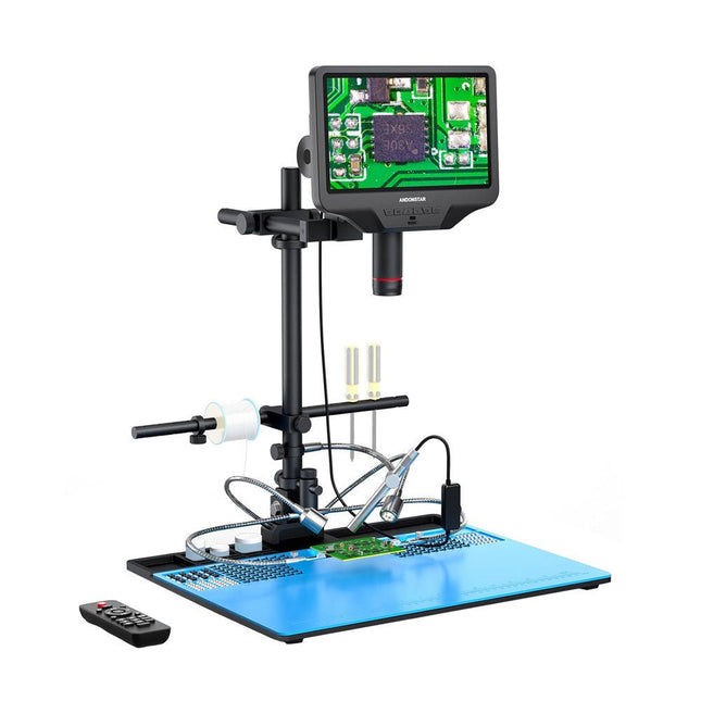
The Andonstar AD409 Max-ES boosts a high-quality metal lens and a unique UV filter design. Crafted from top-tier industrial-grade materials, it delivers unmatched precision and durability, ensuring a reliable product experience. The UV filter positioned in front of the metal lens blocks soldering heat, smoke, and dust, safeguarding the lens and making it perfect for soldering and maintenance professionals.
The AD409 Max-ES features an oversized Max station (46 x 37 x 47.5 cm) and an advanced tool set, expanding the soldering station area by 370%. This upgrade meets the demands of professional soldering tasks and provides ample workspace for larger projects.
The easy-to-use tool holder keeps tools within reach, ensuring they are always accessible. Additionally, the soldering helping hands with rotatable clamps simplify soldering and repair tasks, enhancing efficiency and convenience.
The endoscope offers an all-around 360° view. This allows for clear observation of components from all sides and inside pipes, eliminating blind spots and ensuring thorough inspections.
Features
High-quality Metal Lens and Unique UV Filter Design
New Max station
Easy-to-use Tool Holder and Soldering Helping Hands
Microscope with Endoscope All-around View 360°
Professional HDMI Digital Microscope supports Multiple Output Methods
8 Levels adjustable LEDs
Convenient Wireless Remote Control
Specifications
Screen size
10.1 inch (1280x800)
Image sensor
4 MP
Video output
UHD 2880x2160 (24fps)FHD 1920x1080 (60fps/30fps)HD 1280x720 (120fps)
Video format
MP4
Magnification
Up to 300 times (27 inch HDMI monitor)
Photo resolution
Max. 24 MP (5600x4200)
Photo format
JPG
Focus range
Min. 5 cm
Frame Rate
Max. 120fps
Video interface
HDMI
Storage
microSD card (up to 64 GB)
PC support
Windows, PC software with measurement
Mobile phone, tablet terminal support
Support WiFi connection and measurement
Power source
5 V DC
Light source
2 LEDs with the stand
Endoscope
Yes
Stand size
46 x 37 x 47.5 cm (18.1 x 14.6 x 18.7")
Included
1x Andonstar AD409 Max-ES Digital Microscope
1x Endoscope
1x Stand with 2 LEDs
1x UV filter (already assembled in the lens)
1x Soldering mat
1x Beam
1x Column
1x Tool holder
1x Soldering Helping Hands
1x Power adapter
1x Power cable
1x HDMI cable
1x USB cable
1x IR remote
1x Manual
Downloads
Manual
Software
Example projects with Node-RED, MQTT, WinCC SCADA, Blynk, and ThingSpeak
This comprehensive guide unlocks the power of Modbus TCP/IP communication with Arduino. From the basics of the Modbus protocol right up to full implementation in Arduino projects, the book walks you through the complete process with lucid explanations and practical examples.
Learn how to set up Modbus TCP/IP communication with Arduino for seamless data exchange between devices over a network. Explore different Modbus functions and master reading and writing registers to control your devices remotely. Create Modbus client and server applications to integrate into your Arduino projects, boosting their connectivity and automation level.
With detailed code snippets and illustrations, this guide is perfect for beginners and experienced Arduino enthusiasts alike. Whether you‘re a hobbyist looking to expand your skills or a professional seeking to implement Modbus TCP/IP communication in your projects, this book provides all the knowledge you need to harness the full potential of Modbus with Arduino.
Projects covered in the book:
TCP/IP communication between two Arduino Uno boards
Modbus TCP/IP communication within the Node-RED environment
Combining Arduino, Node-RED, and Blynk IoT cloud
Interfacing Modbus TCP/IP with WinCC SCADA to control sensors
Using MQTT protocol with Ethernet/ESP8266
Connecting to ThingSpeak IoT cloud using Ethernet/ESP8266
Understanding and Using Them Effectively
What happens in electronics is invisible to the naked eye. The instrument that allows to accurately visualize electrical signals, the one through which the effects of electronics become apparent to us, is the oscilloscope.
Alas, when one first ventures into electronics, it is often without an oscilloscope. And one is left fumbling, both physically and mentally. Observing an electrical signal on a screen for the first time is a revelation. Nobody wishes to forgo that marvel again. There is no turning back.
In electronics, if one wishes to progress with both enjoyment and understanding, an oscilloscope is essential. This marks the beginning of a period of questioning: how to choose one? And no sooner is that question answered than a whole string of others arises, which can be summed up in just one: how does one use the oscilloscope in such a way that what it displays truly reflects the reality of the signals?
Rémy Mallard is a passionate communicator with a gift for making complex technical subjects understandable and engaging. In this book, he provides clear answers to essential questions about using an oscilloscope and offers a wealth of guidance to help readers explore and understand the electrical signals behind electronic systems. With his accessible style and practical insights, this book is a valuable tool for anyone eager to deepen their understanding of electronics.
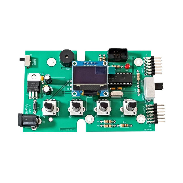
The Elektor Super Servo Tester can control servos and measure servo signals. It can test up to four servo channels at the same time.
The Super Servo Tester comes as a kit. All the parts required to assemble the Super Servo Tester are included in the kit. Assembling the kit requires basic soldering skills. The microcontroller is already programmed.
The Super Servo Tester features two operating modes: Control/Manual and Measure/Inputs.
In Control/Manual mode the Super Servo Tester generates control signals on its outputs for up to four servos or for the flight controller or ESC. The signals are controlled by the four potentiometers.
In Measure/Inputs the Super Servo Tester measures the servo signals connected to its inputs. These signals may come from for instance an ESC, a flight controller, or the receiver or another device. The signals are also routed to the outputs to control the servos or the flight controller or ESC. The results are shown on the display.
Specifications
Operating modes
Control/Manual & Measure/Inputs
Channels
3
Servo signal inputs
4
Servo signal outputs
4
Alarm
Buzzer & LED
Display
0.96' OLED (128 x 32 pixels)
Input voltage on K5
7-12 VDC
Input voltage on K1
5-7.5 VDC
Input current
30 mA (9 VDC on K5, nothing connected to K1 and K2)
Dimensions
113 x 66 x 25 mm
Weight
60 g
Included
Resistors (0.25 W)
R1, R3
1 kΩ, 5%
R2, R4, R5, R6, R7, R9, R10
10 kΩ, 5%
R8
22 Ω, 5%
P1, P2, P3, P4
10 kΩ, lin/B, vertical potentiometer
Capacitors
C1
100 µF 16 V
C2
10 µF 25 V
C3, C4, C7
100 nF
C5, C6
22 pF
Semiconductors
D1
1N5817
D2
LM385Z-2.5
D3
BZX79-C5V1
IC1
7805
IC2
ATmega328P-PU, programmed
LED1
LED, 3 mm, red
T1
2N7000
Miscellaneous
BUZ1
Piezo buzzer with oscillator
K1, K2
2-row, 12-way pinheader, 90°
K5
Barrel jack
K4
1-row, 4-way pin socket
K3
2-row, 6-way boxed pinheader
S1
Slide switch DPDT
S2
Slide switch SPDT
X1
Crystal, 16 MHz
28-way DIP socket for IC2
Elektor PCB
OLED display, 0.96', 128 x 32 pixels, 4-pin I²C interface
Links
Elektor Magazine
Elektor Labs
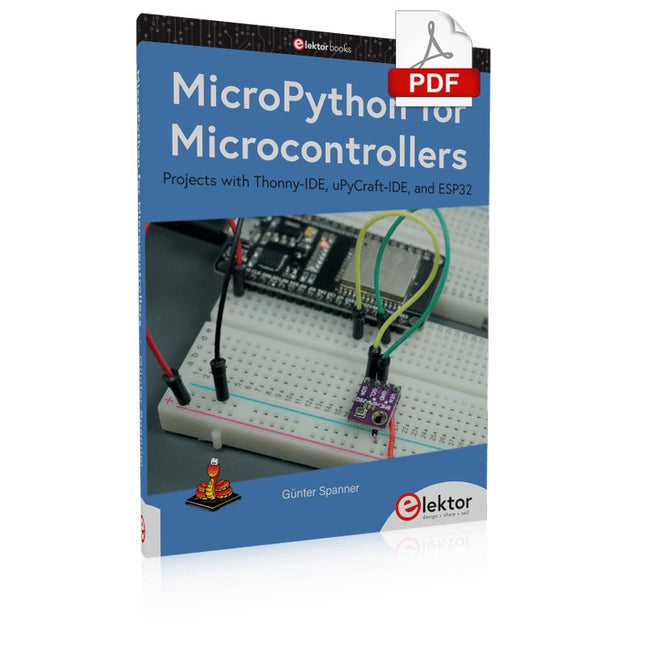
Projects with Thonny-IDE, uPyCraft-IDE, and ESP32
The 'Python' programming language has enjoyed an enormous upswing in recent years. Not least, various single-board systems such as the Raspberry Pi have contributed to its popularity. But Python has also found widespread use in other fields, such as artificial intelligence (AI) or machine learning (ML). It is obvious, therefore, to use Python or the 'MicroPython' variant for use in SoCs (Systems on Chip) as well.
Powerful controllers such as the ESP32 from Espressif Systems offer excellent performance as well as Wi-Fi and Bluetooth functionality at an affordable price. With these features, the Maker scene has been taken by storm. Compared to other controllers, the ESP32 has a significantly larger flash and SRAM memory, as well as a much higher CPU speed. Due to these characteristics, the chip is not only suitable for classic C applications, but also for programming with MicroPython.
This book introduces the application of modern one-chip systems. In addition to the technical background, the focus is on MicroPython itself. After the introduction to the language, the programming skills learned are immediately put into practice. The individual projects are suitable for use in the laboratory as well as for everyday applications. So, in addition to the actual learning effect, the focus is also on the joy of building complete and useful devices. By using laboratory breadboards, circuits of all kinds can be realized with little effort, turning the testing and debugging of the 100% homebrew projects into an instructive pleasure.
The various applications, such as weather stations, digital voltmeters, ultrasound range finders, RFID card readers or function generators, make the projects presented ideally suited for practical courses or subject and study work in the natural sciences, or in science and technology classes.