Bestsellers
-

Rigol Rigol RSA3015E-TG Real-time Spectrum Analyzer (9 kHz – 1.5 GHz)
Highlights Frequency: 1.5 GHz DANL: -161 dBm Phase Noise: -102 dBc/Hz RBW: 1 Hz Specifications Ultra-Real technology Frequency: up to 1.5 GHz Displayed average noise level (DANL): <-161 dBm (typical) Phase noise: <-102 dBc/Hz (typical) Level measurement uncertainty: <1.0 dB 1.5 GHz tracking generator Min. RBW 1 Hz Up to 10 MHz real-time analysis bandwidth Multiple measurement modes Various advanced measurement functions EMI measurement application (option) Multiple trigger modes and trigger masks Density, spectrogram, and other display modes PC software options 10.1'' capacitive multi-touch screen; supporting touch gestures USB, LAN, HDMI and other communication and display interfaces Included 1x Rigol RSA3015E-TG Spectrum Analyzer 1x Power cord 1x USB cable
€ 2.176,79
-

Rigol Rigol DSA815-TG Spectrum Analyzer (9 kHz – 1.5 GHz)
Highlights Frequency: 1.5 GHz DANL: -155 dBm Phase Noise: -80 dBc/Hz RBW: 10 Hz Tracking Generator Specifications All-Digital IF Technology Frequency Range from 9 kHz up to 1.5 GHz Min. -161 dBm Displayed Average Noise Level (Typ.) Min. < -98 dBc/Hz @ 10 kHz Offset Phase Noise Level Measurement Uncertainty < 0.8 dB 10 Hz Minimum Resolution Bandwidth Up to 1.5 GHz Tracking Generator Advanced Measurement Functions (Opt.) EMI Filter & Quasi-Peak Detector Kit (Opt.) VSWR Measurement Kit (Opt.) PC Software (Opt.) Optional RF TX/RX Training Kit Optional RF Accessories (Cable, Adaptor, Attenuator, Bridge ...) Complete Connectivity: LAN (LXI), USB Host & Device, GPIB (Opt.) 8 Inch WVGA (800x480) Display Compact Size, Light Weight Design Included 1x Rigol DSA815-TG Spectrum Analyzer 1x Power cord 1x USB cable
€ 974,66
-
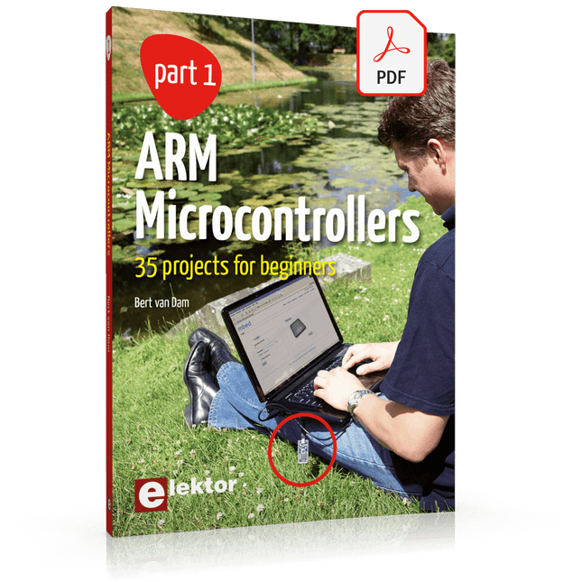
Elektor Digital ARM Microcontrollers (EN) | E-book
35 Projects for Beginners This book is for hobbyists, students and engineers who want to learn C and how to use an mbed ARM microcontroller in an easy and fun way, without the need for cumbersome software installations. ARM mbed microcontroller NXP LPC1768 The projects in this book are meant for beginners in C and ARM microcontrollers. That doesn't mean the projects are simple, but it does mean that they are easy to understand. We use for example USB communications, a subject that is made so easy by the mbed that it is suitable for a beginners book. Cloud technology The mbed NXP LPC1768 uses cloud technology, a revolutionary concept in software development. This means you do not need to install software on your PC in order to program the mbed! The only thing you need is a browser such as Microsoft Internet Explorer, and a USB port on your PC. You can get access to your project from any PC anywhere in the world and continue working on it. When you are done a few simple mouse clicks transfer the program to your mbed hardware. Of course you can optionally download the projects and store them on your own PC. Features of this Book Learn how to program an mbed ARM microcontroller using cloud technology. No complicated software installation on your PC needed. Learn programming in C by doing fun and interesting projects. No previous experience or knowledge required. Examples of projects in this book: flashing light, timer, light activated switch, digital thermometer, people detector, USB communication, talking microcontroller, debugging, sound switch, and much more - 35 projects in total. Examples of C subjects in this book: variables, commands, functions, program execution, pointers (introduction).
€ 29,95
Members € 23,96
-

Velleman Whadda Electronic Dice
This electronic dice with 7 red LEDs rolls when the push button is released and works with a 9 V battery (not included). Downloads Manual
€ 9,95
Members € 8,96
-

Velleman Whadda Flashing LEDs
This educational soldering kit is suitable for all kinds of applications such as model making and works with a 9 V battery (not included). You can control the flashing speed with two potentiometers. Downloads Manual
€ 8,95
Members € 8,06
-
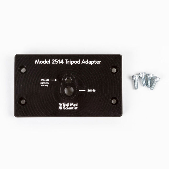
Evil Mad Science Tripod Adapter for AxiDraw
The tripod adapter is custom machined from a solid block of aluminum, and provides two standard tripod mounting points with 3/8-16 and light-duty 1/4-20 thread respectively. This allows you to mount the AxiDraw to a tripod, should you have reason to do so. We would highly recommend using a sturdy tripod with a 3/8-16 connection point and appropriate counterweight (sand bag, lifting weights, etc) to balance the weight of the AxiDraw while in use. Installation is straightforward, and does not require any tools other than those included with AxiDraw: Remove the existing foot pads from the AxiDraw (either standard or outrigger feet, depending on model) and attach this plate to the captured nuts in the bottom surface of the AxiDraw. For AxiDraw SE/A3 (April 2019 and newer), the tripod adapter attaches directly to tapped holes in the base of the machine. This heavy-duty tripod adapter is compatible with AxiDraw V3, AxiDraw V3/A3 and AxiDraw V3 XLX. It is also compatible with AxiDraw SE/A3 manufactured in April 2019 and newer. Specifications Material: Anodized 6061-T6 aluminum Size: 3.90 x 2.36 x 0.35 inches (99.1 x 60 x 8.3 mm) Weight: Approximately 144 g Mounting hardware: included (four M4x10 high-strength steel mounting screws)
€ 29,95
Members € 26,96
-

Evil Mad Science Easel Board for AxiDraw (Tabloid/A3)
Extra easel boards for AxiDraw V3/A3 can be used as replacements, or for staging additional workpieces for quickly swapping to the next plot. This set consists of one 11.75 x 17 inch (29.85 x 43.18 cm) hardboard platen with rubber feet attached, plus eight micro binder clips.
€ 17,95
Members € 16,16
-

Loomia Loomia Double Backlit User Interface
Double Backlit User Interface: The dual backlit button is just like the single backlit button, but twice the fun! Use this component when you need to operate something up and down, or right to left. Using cut-out vinyl, you can create icons and stickers on fabric that show your users button functionality. Features Component: 4.6 x 6.3" Individual Button Size: 1" radius circle Press Durability: Up to 10,000 presses under 5lbf LED Voltage: 5 V
€ 54,95€ 39,95
Members identical
-

Loomia Loomia Single Backlit Button
The single backlit button is a simple mechanical switch that comes with an LED inside. When you press the button, the circuit is completed, driving your pin high or low. Use the embedded LED to make a glowing power icon, logo , or whatever suits your fancy. Features Press durability: Up to 10,000 times pressing under 5lbf (22.24 N) LED Voltage: 5 V Component: 2" x 3" Individual (5,08 x 7,62 cm) Button Size: 1" radius circle (2,54 cm)
€ 49,95€ 29,95
Members identical


