Bestsellers
-
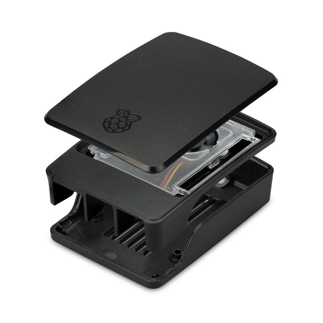
Raspberry Pi Foundation Official Case for Raspberry Pi 5 (black/gray)
The Raspberry Pi 5 case is a refinement of the Raspberry Pi 4 case with improved thermal features to support the higher peak power consumption of the Raspberry Pi 5. It integrates a variable speed fan that is powered and controlled via a dedicated connector on the Raspberry Pi 5.
€ 11,95€ 6,95Best Price
-
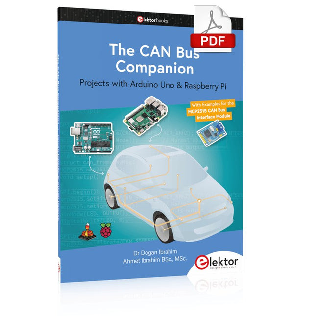
Elektor Digital The CAN Bus Companion (E-book)
Projects with Arduino Uno & Raspberry Pi with Examples for the MCP2515 CAN Bus Interface Module This book details the use of the Arduino Uno and the Raspberry Pi 4 in practical CAN bus based projects. Using either the Arduino Uno or the Raspberry Pi with off-the-shelf CAN bus interface modules considerably ease developing, debugging, and testing CAN bus based projects. This book is written for students, practicing engineers, enthusiasts, and for everyone else wanting to learn more about the CAN bus and its applications. The book assumes that the reader has some knowledge of basic electronics. Knowledge of the C and Python programming languages and programming the Arduino Uno using its IDE and Raspberry Pi will be useful, especially if the reader intends to develop microcontroller-based projects using the CAN bus. The book should be a useful source of reference material for anyone interested in finding answers to questions such as: What bus systems are available for the automotive industry? What are the principles of the CAN bus? How can I create a physical CAN bus? What types of frames (or data packets) are available in a CAN bus system? How can errors be detected in a CAN bus system and how dependable is a CAN bus system? What types of CAN bus controllers exist? How do I use the MCP2515 CAN bus controller? How do I create 2-node Arduino Uno-based CAN bus projects? How do I create 3-node Arduino Uno-based CAN bus projects? How do I set the acceptance masks and acceptance filters? How do I analyze data on the CAN bus? How do I create 2-node Raspberry Pi-based CAN bus projects? How do I create 3-node Raspberry Pi-based CAN bus projects?
€ 32,95
Members: € 29,66
-
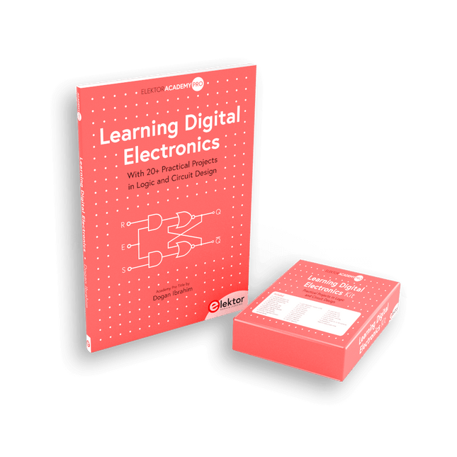
Elektor Bundles Learning Digital Electronics (Bundle)
Master digital electronics – the hands-on way! This bundle includes the book Learning Digital Electronics, featuring 20+ practical projects in Logic and Circuit design, as well as a 100-piece kit – so you can start building logic circuits, counters, displays, and more right away. Learning Digital Electronics (Book) This book is a practical guide to digital electronics, covering the essential components of modern digital systems: number systems, logic gates, Boolean algebra, combinational and sequential logic, and more. Through more than 20 structured projects, you’ll design and build digital systems using real-world components such as logic gates, multiplexers, decoders, flip-flops, counters, and shift registers. The projects range from basic LED logic circuits to digital locks, display systems, traffic light controllers, and timing-based designs. Selected projects introduce the use of tools such as CircuitVerse for circuit simulation, while several designs make use of 74HC-series logic devices, commonly used in digital hardware prototyping. Inside, you’ll find: Clear coverage of number systems and binary arithmetic Logic gate fundamentals and universal gate implementations Step-by-step projects using flip-flops, counters, and registers Real-world design with 74HC-series logic chips Techniques for designing combinational and sequential systems This book takes a design-first, application-driven approach to digital electronics—built around working circuits, tested logic, and hands-on experimentation. Learning Digital Electronics (Kit) This kit has been specially developed to complement the book "Learning Digital Electronics". Since all necessary components are included, you can complete every practical project in the book directly. Kit contents 2x 74HC08 AND gate chip 2x 74HC00 NAND gate chip 1x 74HC86 XOR gate chip 1x 555 timer chip 1x 74HC161 counter chip 1x 74HC164 shift register 1x CD4511 7-segment decoder 1x CD4027 JK flip-flop 1x BC337 NPN transistor 1x KPS-5161 7-segment common-cathode display 1x Light dependent resistor (LDR) 4x 10 KΩ resistors 8x 1 KΩ resistor 2x 47 KΩ resistors 1x 100 KΩ resistor 4x 2.7 KΩ resistors 1x 5.6 KΩ resistor 1x 150 KΩ resistor 1x 10 μF capacitor 2x 0.01 μF capacitor 2x 100 nF capacitor 8x Small red LED 1x Small green LED 1x Small orange LED 4x Pushbutton switches 1x Active buzzer 1x Battery holder for 3x AA batteries (batteries not included) 1x Breadboard 40x Male-to-male jumper wires (length: 200 mm)
€ 69,95€ 59,95Best Price
-
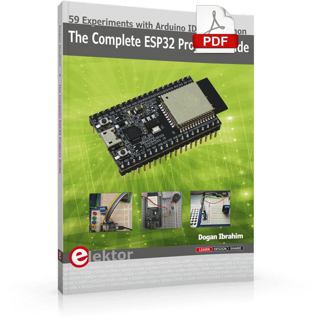
Elektor Digital The Complete ESP32 Projects Guide (E-book)
59 Experiments with Arduino IDE and Python The main aim of this book is to teach the Arduino IDE and MicroPython programming languages in ESP32 based projects, using the highly popular ESP32 DevKitC development board. Many simple, basic, and intermediate level projects are provided in the book using the Arduino IDE with ESP32 DevKitC. All projects have been tested and work. Block diagrams, circuit diagrams, and complete program listings of all projects are given with explanations. In addition, several projects are provided for programming the ESP32 DevKitC using MicroPython. The projects provided in this book are designed to teach the following features of the ESP32 processor: GPIOs Touch sensors External interrupts Timer interrupts I²C and I²S SPI PWM ADC DAC UART Hall sensor Temperature sensor Infrared controller Reading and writing to SD card Reading and writing to flash memory RTC timer Chip ID Security and encryption Wi-Fi and network programming Bluetooth BLE programming Communication mobile devices Low power design ESP-IDF programming The projects have been organized with increasing levels of difficulty. Readers are encouraged to tackle the projects in the order given. A specially prepared hardware kit (SKU 18305) is available from Elektor. With the help of this hardware, it should be easy and fun to build the projects in this book.
€ 34,95
Members: € 31,46
-

Elektor Digital SDR Hands-on Book (E-book)
The short-wave technique has a very particular appeal: It can easily bridge long distances. By reflecting short-wave signals off the conductive layers of the ionosphere, they can be received in places beyond the horizon and therefore can reach anywhere on earth. Although technology is striving for ever higher frequencies, and radio is usually listened to on FM, DAB+, satellite or the Internet, modern means of transmission require extensive infrastructure and are extremely vulnerable. In the event of a global power outage, there is nothing more important than the short-wave. Amateur radio is not only a hobby, it’s also an emergency radio system! Elektor’s SDR-Shield is a versatile shortwave receiver up to 30 MHz. Using an Arduino and the appropriate software, radio stations, morse signals, SSB stations, and digital signals can be received. In this book, successful author and enthusiastic radio amateur, Burkhard Kainka describes the modern practice of software defined radio using the Elektor SDR Shield. He not only imparts a theoretical background but also explains numerous open source software tools.
€ 29,95
Members: € 26,96
-
Elektor Digital Raspberry Pi 5 for Radio Amateurs (E-book)
Program and Build Raspberry Pi 5 Based Ham Station Utilities with the RTL-SDR The RTL-SDR devices (V3 and V4) have gained popularity among radio amateurs because of their very low cost and rich features. A basic system may consist of a USB based RTL-SDR device (dongle) with a suitable antenna, a Raspberry Pi 5 computer, a USB based external audio input-output adapter, and software installed on the Raspberry Pi 5 computer. With such a modest setup, it is possible to receive signals from around 24 MHz to over 1.7 GHz. This book is aimed at amateur radio enthusiasts and electronic engineering students, as well as at anyone interested in learning to use the Raspberry Pi 5 to build electronic projects. The book is suitable for both beginners through experienced readers. Some knowledge of the Python programming language is required to understand and eventually modify the projects given in the book. A block diagram, a circuit diagram, and a complete Python program listing is given for each project, alongside a comprehensive description. The following popular RTL-SDR programs are discussed in detail, aided by step-by-step installation guides for practical use on a Raspberry Pi 5: SimpleFM GQRX SDR++ CubicSDR RTL-SDR Server Dump1090 FLDIGI Quick RTL_433 aldo xcwcp GPredict TWCLOCK CQRLOG klog Morse2Ascii PyQSO Welle.io Ham Clock CHIRP xastir qsstv flrig XyGrib FreeDV Qtel (EchoLink) XDX (DX-Cluster) WSJT-X The application of the Python programming language on the latest Raspberry Pi 5 platform precludes the use of the programs in the book from working on older versions of Raspberry Pi computers.
€ 32,95
Members: € 29,66
-
Elektor Publishing Consumer Electronics Repair, Reuse and Recycling
A Combat Guide against E-waste and Throwawayism This book is for anyone who enjoys tinkering with analog and digital hardware electronics. Regardless of the sophistication of your workspace, only basic tools are required to achieve truly satisfying results. It is intended as a reference guide among other hardware repair publications you may have in your library. However, the book goes a step further than most other repair guides in addressing issues in the modern era of discarded electronics called e-waste. E-waste should be put to good use. Producing anything new requires not just precious resources and labor, but also energy to make and deliver it to global retail shelves. Your talents and love of electronics can be put to good use by rescuing and resurrecting at least selected units from this endless stream of e-waste. Examples include either restoring through repair, or salvaging reusable electronic and mechanical components for your next project. Smart tips are provided throughout the book, and much information is tabulated for easy reference. The book expands age-old repair and hacking techniques applied for repair on the workbench into clever methods and applications to achieve effective results with discarded or “non-servicable” electronic consumer products. The final chapter provides real-life examples using all of the previously discussed content in a summarized form for each example repair type.
€ 39,95
Members: € 35,96
-
Elektor Publishing KiCad Like A Pro – Fundamentals and Projects
Getting started with the world’s best open-source PCB tool The latest iteration of KiCad, the world’s best free-to-use Printed Circuit Board tool, is packed with features usually found only in expensive commercial CAD tools. This modern, cross-platform application suite built around schematic and design editors, with auxiliary applications is a stable and mature PCB tool. KiCad 8 is a perfect fit for electronic engineers and makers. Here are the most significant improvements and features in KiCad 8, both over and under the hood: Modern user interface, completely redesigned from earlier versions Improved and customizable electrical and design rule checkers Theme editor allowing you to customize KiCad on your screen Ability to import projects from Eagle, CADSTART, and more Python scripting API Improved integrated SPICE circuit simulator Multi-sheet schematics Filters define selectable elements Enhanced interactive router helps you draw single tracks and differential pairs with precision New or enhanced tools to draw tracks, measure distances, tune track lengths, etc. Advanced interactive router Built-in bill of materials generator Realistic ray-tracing capable 3D viewer Customizable teardrops Plug-in manager for quick installation of themes, libraries and functionalities such as autorouters and BOM generators This book will teach you to use KiCad through a practical approach. It will help you become productive quickly and start designing your own boards. Example projects illustrate the basic features of KiCad, even if you have no prior knowledge of PCB design. The author describes the entire workflow from schematic entry to the intricacies of finalizing the files for PCB production and offers sound guidance on the process. Further full-fledged projects, of incremental difficulty, will be presented in a second book, together with a variety of advanced recipes.
€ 54,95
Members: € 49,46
-

Elektor Classics Elektor Archive 1974-2025 (USB Stick) EN
52 Volumes on USB – Now incl. Volume 2025! NEW: For articles from the year 2000 onwards, there is now a separate download option for additional materials such as PCB layouts, Gerber files, and software! This USB stick (64 GB, USB 3.0) is loaded with all the Elektor magazine English editions (as PDFs) from 1974 to 2025. Elektor engineers, authors, and editors aim to inspire you to master electronics and computer technology by presenting professionally designed circuits that are easy to build. We also cover the latest developments in electronics and information technology. With the Elektor Archive on a USB stick, you can browse our previous English editions at your convenience and learn about MCU-based projects, robotics, electronics testing, embedded programming, analog techniques, and much more. All the Elektor magazine editions are stored as PDFs on a 32-GB USB stick (USB 3.0). The 10,000+ articles have been classified by date of publication (month/year), and a comprehensive index enables you to search the entire USB stick. Subject areas include: Audio & video Computers & microcontrollers Radio, hobby & modelling Home & garden Power supplies & batteries Test & measurement Software And everything else that doesn’t fit in one of these categories. Elektor GPT Elektor GPT is an AI-powered tool that helps users navigate through the decades-long Elektor archive. Using advanced search algorithms and natural language processing, Elektor GPT quickly finds articles, projects, and other resources from the archive. Specifications Storage 64 GB Interfaces 1x USB-A1x USB-C System requirements PC with Adobe Reader 7.0 or higher Web browser
€ 199,95€ 99,95Best Price
-

Elektor Digital Explore ATtiny Microcontrollers using C and Assembly Language (E-book)
AVR Architecture and Programming An in-depth look at the 8-bit AVR architecture found in ATtiny and ATmega microcontrollers, mainly from a software and programming point of view. Explore the AVR architecture using C and assembly language in Microchip Studio (formerly Atmel Studio) with ATtiny microcontrollers. Learn the details of how AVR microcontrollers work internally, including the internal registers and memory map of ATtiny devices. Program ATtiny microcontrollers using an Atmel-ICE programmer/debugger, or use a cheap hobby programmer, or even an Arduino Uno as a programmer. Most code examples can be run using the Microchip Studio AVR simulator. Learn to write programs for ATtiny microcontrollers in assembly language. See how assembly language is converted to machine code instructions by the assembler program. Find out how programs written in the C programming language end up as assembly language and finally as machine code instructions. Use the Microchip Studio debugger in combination with a hardware USB programmer/debugger to test assembly and C language programs, or use the Microchip Studio AVR simulator. DIP packaged ATtiny microcontrollers are used in this volume for easy use on electronic breadboards, targeting mainly the ATtiny13(A) and ATtiny25/45/85. Learn about instruction timing and clocks in AVR microcontrollers using ATtiny devices. Be on your way to becoming an AVR expert with advanced debugging and programming skills.
€ 34,95
Members: € 31,46
-
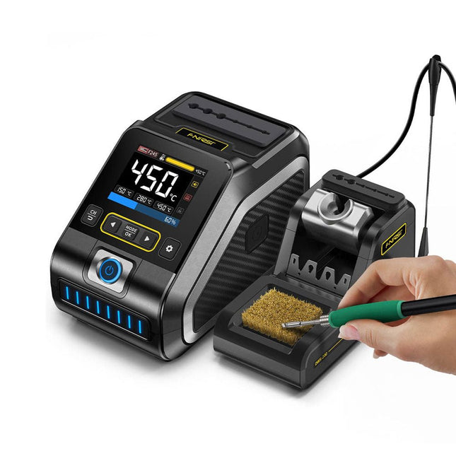
FNIRSI FNIRSI DWS-200 Smart Soldering Station (with F245 Handle + 6 Soldering Tips)
The FNIRSI DWS-200 is a powerful 200 W smart soldering station, ideal for electronic soldering applications. Powered by a switch-mode power supply, it operates smoothly with a wide voltage input range of 100-240 V. The station provides an adjustable temperature range from 100°C to 450°C (212°F to 842°F) and allows for easy switching between °C and °F. To enhance efficiency, it supports up to three preset temperature values and can connect to a soldering iron stand for standby mode activation. The station also features a dynamic temperature curve mode for real-time data monitoring, ensuring precise and consistent performance in demanding soldering tasks. Features Maximum power output of 200 W, allowing for fast heating Wide adaptive voltage input of 100-240 V 2.8" HD color TFT display with intelligent control Multiple preset groups to switch between different settings quickly Supports F245 and F210 soldering handle types, offering flexibility for different soldering applications Real-time sleep mode to extend the life of the soldering tip Multi-mode real-time monitoring for power and temperature status, enhancing safety and precision Specifications Peak Power 200 W (max) Temperature Range 100°C~450°C (212°F~842°F) Display 2.8" TFT HD Color Screen Heating Time 1 sec Melting Time 3 sec Input Voltage 100-240 V (AC) Input Fuse 3 A Soldering Handle Type F245 Dimensions (Station) 156 x 96 x 103 mm Weight (Station) 475 g Included 1x FNIRSI DWS-200 Soldering Station 1x Soldering Handle F245 6x Soldering Tips (B, KU, K, C2, I, JS) 1x Connecting Cable 2x Helping Hands 1x Power Cable (EU) Downloads Manual Firmware V1.3
€ 179,00
-
Elektor Digital Mastering FPGA Chip Design (E-book)
For Speed, Area, Power, and Reliability This book teaches the fundamentals of FPGA operation, covering basic CMOS transistor theory to designing digital FPGA chips using LUTs, flip-flops, and embedded memories. Ideal for electrical engineers aiming to design large digital chips using FPGA technology. Discover: The inner workings of FPGA architecture and functionality. Hardware Description Languages (HDL) like Verilog and VHDL. The EDA tool flow for converting HDL source into a functional FPGA chip design. Insider tips for reliable, low power, and high performance FPGA designs. Example designs include: Computer-to-FPGA UART serial communication. An open-source Sump3 logic analyzer implementation. A fully functional graphics controller. What you need: Digilent BASYS3 or similar FPGA eval board with an AMD/Xilinx FPGA. Vivado EDA tool suite (available for download from AMD website free of charge). Project source files available from author’s GitHub site.
€ 32,95
Members: € 29,66
-
Elektor Digital Motor Control - Projects with Arduino & Raspberry Pi (E-book)
This book is about DC electric motors and their use in Arduino and Raspberry Pi Zero W based projects. The book includes many tested and working projects where each project has the following sub-headings: Title of the project Description of the project Block diagram Circuit diagram Project assembly Complete program listing of the project Full description of the program The projects in the book cover the standard DC motors, stepper motors, servo motors, and mobile robots. The book is aimed at students, hobbyists, and anyone else interested in developing microcontroller based projects using the Arduino Uno or the Raspberry Pi Zero W. One of the nice features of this book is that it gives complete projects for remote control of a mobile robot from a mobile phone, using the Arduino Uno as well as the Raspberry Pi Zero W development boards. These projects are developed using Wi-Fi as well as the Bluetooth connectivity with the mobile phone. Readers should be able to move a robot forward, reverse, turn left, or turn right by sending simple commands from a mobile phone. Full program listings of all the projects as well as the detailed program descriptions are given in the book. Users should be able to use the projects as they are presented, or modify them to suit to their own needs.
€ 29,95
Members: € 26,96
-

SEQURE SEQURE HT140 (2-in-1) SMD Soldering & Desoldering Tweezers
The SEQURE HT140 is a highly versatile 2-in-1 soldering tool that combines the functionality of hot tweezers and a soldering iron. It is specifically engineered for precise SMD soldering and desoldering tasks. With independent control for single-sided heating, it operates as a traditional soldering iron when fitted with a standard tip. When configured for dual-sided heating, it transforms into hot tweezers – perfect for the efficient and accurate removal of SMD components. Features Working Temperature: 50-500°C (122-932°F) Supports multiple power inputs: PD 3.1/3.0/2.0, QC 3.0/2.0, (5-28 V DC), LiPo batteries, and power adapters. The HT140 combines hot tweezers and a soldering iron, with independent single- or dual-sided heating. Use it as a soldering iron with a tip, or as hot tweezers for easy SMD desoldering. Voltage and current can be adjusted based on the power source. Features dual temperature control, presets, quick temperature increase, and fine-tuning. 128 x 32 OLED screen with adjustable brightness, and orientation. Switchable °C/°F. High-precision heating element with ±1% accuracy. Melts solder in just 2 seconds. Smart standby, sleep, and wake-up functions extend tip lifespan and boost efficiency. Supports temperature calibration and compensation for precise work. Includes a 1.5 m heat-resistant PD 150 W silicone cable and a sturdy all-metal HT Station. Swappable tips and adjustable angles for various SMD soldering tasks. Specifications Working Voltage 5-28 V DC Maximum Power 140 W Working Temperature 50-500°C (122-932°F) Tin Melting Time 2s Interface Type USB-C, DC5525 Power Supply PD 3.1/3.0/2.0, QC 3.0/2.0, 28 V DC max Display 128 x 32 OLED Firmware Upgrade Yes Menu Languages English, Russian, Chinese Dimensions 160 x 27 x 17.5 mm Weight 50 g Included 1x SEQURE HT140 Host 2x HT140-IS Tapered Curved Desoldering Tips 1x HT Station 1x Accessory Package 1x Storage Bag 1x 65 W PD Power Supply (EU, UK & US) 1x 24 W PD Silicone Wire (1.5 m) 1x GND Wire Accessory Kit (1.8 m)
€ 119,95€ 99,95Best Price
-
Elektor Digital Elektor Special: Introduction to Electronics with Arduino (PDF)
Although the Arduino isn’t a novelty any longer, there are still many beginners who want to try programming and development with a microcontroller, and to them, it is all new. All beginnings can be difficult, though they should be light and enjoyable. You do not need much or expensive equipment for the examples. The circuits are built on a small breadboard, and, if necessary, connected to an Arduino Uno, which you can program on a Windows PC. You will find clear examples of how to build all circuits, ensuring easy and error-free reproduction. Projects Discussed Current & Voltage – How it all began Arduino Hardware Arduino Programming The Electrical Circuit Measuring with the Multimeter Circuit Diagrams and Breadboards Creating Circuit Diagrams Breadboard Views with Fritzing Online Circuit Simulation Indispensable: Resistors (Part 1) Hands-on with Resistors (Part 2) Variable Resistors Diodes: One-way Street for Current The Transistor Switch Electromagnetism Relays and Motors op-amps: Operational Amplifiers Capacitors The NE555 Timer PWM and Analogue Values with Arduino 7-Segment Temperature Display Introduction to Soldering and LCDs
€ 11,95
Members: € 10,76
-
Elektor Publishing Electric Guitar (2nd Edition)
Sound Secrets and Technology What would today’s rock and pop music be without electric lead and bass guitars? These instruments have been setting the tone for more than sixty years. Their underlying sound is determined largely by their electrical components. But, how do they actually work? Almost no one is able to explain this to the true musician with no technical background. This book answers many questions simply, in an easily-understandable manner. For the interested musician (and others), this book unveils, in a simple and well-grounded way, what have, until now, been regarded as manufacturer secrets. The examination explores deep within the guitar, including pickups and electrical environment, so that guitar electronics are no longer considered highly secret. With a few deft interventions, many instruments can be rendered more versatile and made to sound a lot better – in the most cost-effective manner. The author is an experienced electronics professional and active musician. He has thoroughly tested everything described here, in practice.
€ 39,95
Members: € 35,96
-

Elektor Publishing Introduction to Electronic Filters
Learn RC and RL Filters with Hands-On Circuits and Simulation Introduction to Electronic Filters is your comprehensive guide to understanding, designing, and applying first-order electronic filters using resistors, capacitors, and inductors. Whether you are a student, maker, or educator, this book demystifies the theory behind RC and RL filters and bridges the gap between concepts and real-world applications through simulation and experimentation. From the basics of frequency response and phase shift to hands-on breadboard builds and Python-based simulations, this book offers a deeply practical learning experience. You will learn to analyse filters using Bode plots and phasors, and explore applications in audio tone shaping, sensor signal conditioning, noise reduction, and power supply filtering. As you progress, you’ll build, measure, simulate, and tune filters using modern tools like CircuitLab, Python, and the Analog Discovery 3. Each chapter includes thoughtfully crafted activities that reinforce learning by doing – designing filters for specific tasks, simulating dynamic behaviour, and observing how theory translates into performance. Inside you’ll find: A clear introduction to the fundamentals of electronic filters Detailed explanations of RC and RL filters, cutoff frequency, and phase Guided activities using both simulation and hardware tools Real-life applications in audio, sensors, power supplies, and more A beginner-friendly primer on Python and algebra for electronics Whether you’re working through simulations or experimenting with real components on your workbench, this book will help you develop a solid understanding of electronic filters and their role in practical circuits.
€ 39,95
Members: € 35,96
-
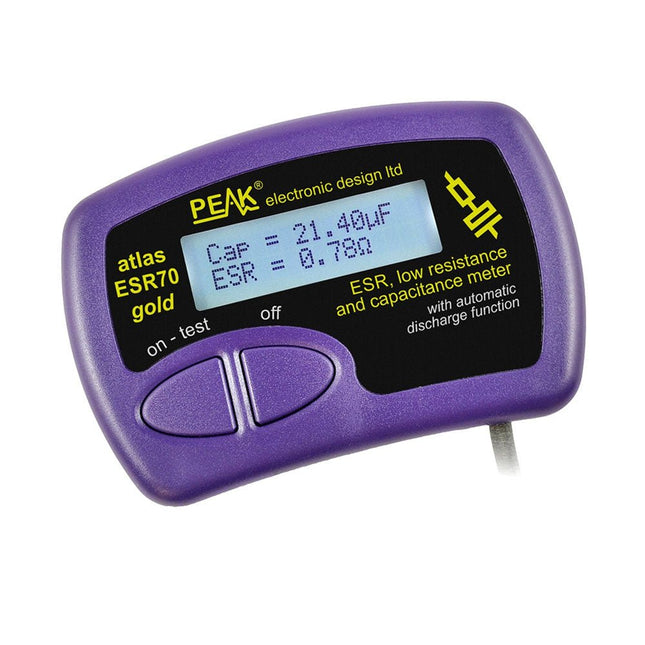
Peak Peak Atlas ESR70 gold (ESR and Capacitance Meter)
The Peak Atlas ESR70 gold is an enhanced version of the previous Peak Atlas ESR70 Plus. It does everything that the ESR70 Plus did but better. It now measures capacitance up to 10x faster, and over a wider range, thanks to new test algorithms. The capacitance measurement is also much less influenced by parallel resistances or leakage current thanks to our new Triple-Slope measurement system. Using the supplied gold plated probes (removable), the Atlas ESR70 gold can measure ESR down to a resolution of 0.01 ohms, up to 40 ohms. It can even measure ESR for capacitors that are in-circuit. Probes are removable, allowing 2 mm compatible probes to be fitted. Audible alerts are produced for various ESR levels allowing you to perform many tests in succession without having to look at the display. The ESR70 automatically takes capacitive reactance into account, so even low value capacitors (down to 0.3 uF) can have the ESR measured accurately. Features Uses a single AAA Alkaline cell (included) Alphanumeric LCD with backlight Automatic analysis-start when you apply the probes Automatic capacitor discharge using controlled discharge function ESR (and low DC resistance) measurement (even in-circuit) Capacitive reactance automatically taken into account to ensure accurate ESR Capacitance measurement (if testing out-of-circuit) Audible alerts for various ESR levels Extended ESR measurement range up to 40 Ohms Optional probe alternatives easily fitted New gold Features Improved LCD with better backlight 10x faster capacitance measurement for large capacitors Enhanced user options system New triple-slope measurement system to vastly reduce the influence of parallel resistance and/or leakage current on capacitance measurements Much wider capacitance measurement range now 0.3 uF to 90,000 uF (was 1uF to 22,000uF) Specifications Analyzer type ESR and Capacitance Component types Capacitors (>0.3 uF) ESR range 0.00 Ohms to 40.0 Ohms ESR resolution From 0.01 Ohms In-circuit use ESR only Capacitance range 0.3 uF to 90000 uF Battery type 1.5 V Alkaline AAA Cell (supplied). Life typically 1500 ops Display type Alphanumeric LCD (with backlight) Included Peak Atlas ESR70 gold Extra-long and extra-flexible test cables (450 mm of Silicone covered cable) 2 mm gold plated plugs and sockets with removeable gold plated crocodile clips Comprehensive illustrated user guide AAA Alkaline cell Downloads Datasheet (EN) User Guide (EN) User Guide (FR) User Guide (IT)
€ 143,99
-

Elektor Digital Build Your Own Multifunctional 4-Axis CNC Machine (E-book)
Plot, Cut, Drill, Mill and Laser with the Z99 This book covers the construction, hardware, software, and operation of the Z99 – CNC machine. This is a multifunctional 4-axis machine for home construction. The capabilities of the Z99 machine include: large-format schematic plotting PCB plotting with etch-resist pens schematic plotting with conductive-ink pens letter cutting out of vinyl paper cutting PCB/substrate drilling PCB/substrate milling text milling laser engraving laser cutting of solder paste masks By making the support software available as freeware, readers of the book are challenged and encouraged to develop new applications for the Z99. The machine would not be of much use if the user has no option to create suitable files for the designs in mind. A large part of this book is dedicated to creating source files in a variety of freeware software packages, including Inkscape, DesignSpark PCB, KiCad, and FlatCAM. The book is also useful for readers keen to comprehend and then master the basic structure of HPGL, Gerber, Drill, and G-code files, as well as to have a go at deciphering them using software.
€ 29,95
Members: € 26,96
-
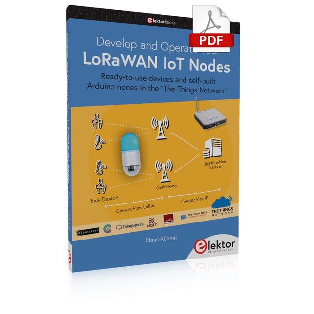
Elektor Digital Develop and Operate Your LoRaWAN IoT Nodes (E-book)
Ready-to-use devices and self-built Arduino nodes in the 'The Things Network' LoRaWAN has developed excellently as a communication solution in the IoT. The Things Network (TTN) has contributed to this. The Things Network was upgraded to The Things Stack Community Edition (TTS (CE)). The TTN V2 clusters were closed towards the end of 2021. This book shows you the necessary steps to operate LoRaWAN nodes using TTS (CE) and maybe extend the network of gateways with an own gateway. Meanwhile, there are even LoRaWAN gateways suitable for mobile use with which you can connect to the TTN server via your cell phone. The author presents several commercial LoRaWAN nodes and new, low-cost and battery-powered hardware for building autonomous LoRaWAN nodes. Registering LoRaWAN nodes and gateways in the TTS (CE), providing the collected data via MQTT and visualization via Node-RED, Cayenne, Thingspeak, and Datacake enable complex IoT projects and completely new applications at very low cost. This book will enable you to provide and visualize data collected with battery-powered sensors (LoRaWAN nodes) wirelessly on the Internet. You will learn the basics for smart city and IoT applications that enable, for example, the measurement of air quality, water levels, snow depths, the determination of free parking spaces (smart parking), and the intelligent control of street lighting (smart lighting), among others.
€ 32,95
Members: € 29,66
-

FNIRSI 65 W USB-C PD GaN Power Supply
With this 65 W USB-C PD power supply (with GaN technology) you can start using the FNIRSI HS-01 soldering iron straight away. Of course, you can also use this charger to fast charge your tablets and smartphones via USB-C and USB-A. Included 65 W USB-C PD GaN Power Supply (EU)
€ 25,00
-
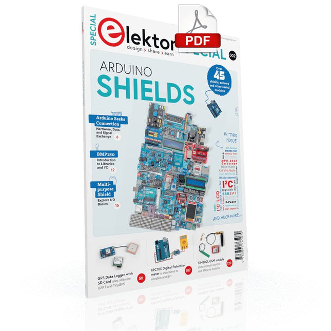
Elektor Digital Elektor Special: Arduino Shields (PDF) EN
Make your project dreams come true: an odometer for the hamster wheel, a fully automatic control of your ant farm with web interface, or the Sandwich-O-Mat – a machine that toasts and grills sandwiches of your choice. With the Arduino and the DIY or Maker movement, not only did entry into microcontroller programming become child's play, but a second development also took place: Resourceful developers brought small boards – so-called shields or modules – to the market, which greatly simplified the use of additional hardware. The small modules contain all the important electronic parts to be connected to the microcontroller with a few plug-in cables, eliminating the need for a fiddly and time-consuming assembly on the plug-in board. In addition, it is also possible to handle tiny components that do not have any connecting legs (so-called SMDs). Projects Discussed Arduino seeks connection BMP and introduction to libraries, I²C Learn I/O basics with the multi-purpose shield I²C LCD adapter and DOT matrix displays LCD keypad shield Level converter W5100: Internet connection I/O expansion shield Relays and solid-state relays The multi-function shield: A universal control unit Connecting an SD card reader via SPI Keys and 7-segment displays 16-bit ADC MCP4725 DAC 16-way PWM servo driver MP3 player GPS data logger using an SD card Touch sensor Joystick SHT31: Temperature and humidity VEML6070 UV-A sensor VL53L0X time-of-flight Ultrasonic distance meter MAX7219-based LED DOT matrix display DS3231 RTC Port expander MCP23017 433 MHz radio MPU-650 gyroscope ADXL345 accelerometer WS2812 RGB LEDs Power supply MQ-xx gas sensors CO2 gas sensor ACS712 current sensor INA219 current sensor L298 motor driver MFRC522 RFID 28BYJ-48 stepper motor TMC2209 silent step stick X9C10x digital potentiometer ST7735 in a color TFT display e-Paper display Bluetooth Geiger counter SIM800L GSM module I²C multiplexer Controller Area Network
€ 11,95
Members: € 10,76
-
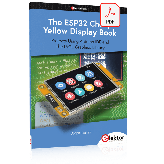
Elektor Digital The ESP32 Cheap Yellow Display Book (PDF)
Projects Using Arduino IDE and the LVGL Graphics Library The ESP32 is probably one of the most popular microcontrollers used by many people, including students, hobbyists, and professional engineers. Its low cost, coupled with rich features makes it a popular device to use in many projects. Recently, a board called the ESP32 Cheap Yellow Display (CYD for short) is available from its manufacturers. The board includes a standard ESP32 microcontroller together with a 320x240 pixel TFT display. Additionally, the board provides several connectors for interfaces such as GPIO, serial port (TX/RX), power and Ground. The inclusion of a TFT display is a real advantage as it enables users to design complex graphics-based projects without resorting to an external LCD or graphics displays. The book describes the basic hardware of the ESP32 CYD board and provides details of its on-board connectors. Many basic, simple, and intermediate-level projects are given in the book based on the ESP32 CYD, using the highly popular Arduino IDE 2.0 integrated development environment. The use of both the basic graphics functions and the use of the popular LVGL graphics library are discussed in the book and projects are given that use both types of approaches. All the projects given in the book have been tested and are working. The block diagram, circuit diagram, and the complete program listings and program descriptions of all the projects are given with explanations. Readers can use the LVGL graphics library to design highly popular eye-catching full-color graphics projects using widgets such as buttons, labels, calendars, keypads, keyboards, message boxes, spinboxes, sliders, charts, tables, menus, bars, switches, drop-down lists, animations, and many more widgets.
€ 29,95
Members: € 26,96
-
Elektor Digital Radio Builder's Book (PDF)
From Detector to Software Defined RadioRadio frequency (RF) technology is one of the areas which still allows putting your own ideas into practice. Countless circuit variants with special objectives allow space for meaningful experiments and projects. Many things simply aren’t available off the shelf. Crystal detector radios without their own power source, simple tube receivers with a touch of nostalgia, the first reception attempts at Software Defined Radio, special receivers for amateur radio, all this can be realized with little effort and as a perfect introduction to RF electronics.For a long time, radio construction was the first step into electronics. Meanwhile, there are other ways, especially via computers, microcontrollers, and digital technology. However, the analog roots of electronics are often neglected. Elementary radio technology and easy-to-do experiments are particularly well suited as a learning field for electronics because you can start with the simplest basics here.But the connection to modern digital technology is also obvious, for example, when it comes to modern tuning methods such as PLL and DDS or modern DSP radios.This book aims to give an overview and present a collection of simple RF projects. The author would like to support you to develop your own ideas, to design your own receivers and to test them.
€ 32,95
Members: € 29,66


