The Nicla Sense ME is a tiny, low-power tool that sets a new standard for intelligent sensing solutions. With the simplicity of integration and scalability of the Arduino ecosystem, the board combines four state-of-the-art sensors from Bosch Sensortec:
BHI260AP motion sensor system with integrated AI
BMM150 magnetometer
BMP390 pressure sensor
BME688 4-in-1 gas sensor with AI and integrated high-linearity, as well as high-accuracy pressure, humidity and temperature sensors.
The Arduino Nicla Sense ME is the smallest Arduino form factor yet, with a range of industrial grade sensors packed into a tiny footprint. Measure process parameters such as temperature, humidity and movement. Featuring a 9-axis inertial measurement unit and the possibility for Bluetooth Low Energy connectivity, it can help you to create your next Bluetooth Low Energy enabled project. Make your own industrial grade wireless sensing network with the onboard BHI260AP, BMP390, BMM150 and BME688 Bosch sensors.
Features
Tiny size, packed with features
Low power consumption
Add sensing capabilities to existing projects
When battery-powered, becomes a complete standalone board
Powerful processor, capable of hosting intelligence on the Edge
Measures motion and environmental parameters
Robust hardware including industrial-grade sensors with embedded AI
BLE connectivity maximizes compatibility with professional and consumer equipment
24/7 always-on sensor data processing at ultra-low power consumption
Specifications
BHI260AP – Self-learning AI smart sensor with integrated accelerometer and gyroscope
BMP390 – Digital pressure sensor
BMM150 – Geomagnetic sensor
BME688 – Digital low power gas, pressure, temperature & humidity sensor with AI
Microcontroller
64 MHz ARM Cortex-M4 (nRF52832)
Sensors
I/O
Castellated pins with the following features:
1x I²C bus (with ext. ESLOV connector)
1x Serial port
1x SPI
2x ADC, programmable I/O voltage from 1.8-3.3 V
Connectivity
Bluetooth 4.2
Power
Micro USB (USB-B), Pin Header, 3.7 V Li-po battery with Integrated battery charger
Memory
512 KB Flash / 64 KB RAM
2 MB SPI Flash for storage
2 MB QSPI dedicated for BHI260AP
Interface
USB interface with debug functionality
Dimensions
22.86 x 22.86 mm
Weight
2 g
Downloads
Datasheet
The JOY-iT R301T fingerprint sensor module is capable of image collection and algorithm calculation due to this integrated chip. Another remarkable function of the sensor is, that it can recognize the fingerprint in different conditions, for example humidity, light texture or changes of the skin. This offers a very wide range of possible applications to secure locks and doors among others. The chip can send data via UART, TTL serial and USB to the connected controller.
Specifications
Model
JP2000 sensor
Chip
32 Bit ARM Cortex-M3
Chip storage
96 kB RAM, 1 MB Flash
Power supply
4.2-6.0 V
Working current
Typical: 40 mAPeak: 50 mA
Logic level
3,3/5 V TTL Logic
Fingerprint storage capacity
3000 Prints
Matching mode
1:N Identification1:1 Verification
Adjustable security level
1 - 5 levels(default security level: 3)
False acceptance rate
< 0.001%(on security level 3)
False acceptance rate
< 0.1%(on security level 3)
Response time
Pre-treatment: < 0.45 sMatch: < 1.5 s
Baud rate support
9600 - 921600
UART communication
No parity, Stop Bit: 1
Dimensions
42 x 19 x 8 mm
Included
1x Fingerprint sensor COM-FP-R301T
1x Cable
Downloads
Datasheet
Manual
Elektor GREEN and GOLD members can download their digital edition here.
Not a member yet? Click here.
Relio v1.0 - Presence Detection and Remote ControlA Matter-Enabled Smart Controller for AC Appliances
Designing Better PCBsA Practical Guide for Professionals and Makers
KiCad 9Top New and Updated Features
Precision Picoammeter (1)With Curve Tracer Functionality Down to the pA range!
Christmas Star 2025A Star Is Soldered
100 mV Continuity Tester
Who’s Pushing the Boundaries of European Electronics?Companies to Watch
productronica 2025: What’s New in Electronics Development and Production
Automation to Tackle Reshoring Manufacturing, Tariffs and Labour Shortages
Beyond Future ProofCircularity in Electronics
Passive ComponentsLow-Loss Inductors Enabling High-Efficiency DC/DC Converters
How Desktop Manufacturing Machines Are Democratizing PCB Production
Starting Out in Electronics...Needs Power
UHD Displays Driven with EaseYour Guide to Easily Put Various TFT-LCDs Into Operation Quickly
Soldering in 2025Practical Soldering Tips Straight from the Workbench
SimulIDEAn All-in-One Tool for Circuit Prototyping
2025: An AI OdysseyFrom Autocomplete to Colleague
Wordy Christmas TreeA Festive Electronics Project with a Linguistic Twist
Err-lectronicsCorrections, Updates, and Readers’ Letters
Analog Pipeline DistortionA Cool Audio Effect For Guitars and Other Instruments
ESP32 Audio Transceiver Board (Part 3)Stereo Transmission and Dual Radio
Learn RC and RL Filters with Hands-On Circuits and Simulation
Introduction to Electronic Filters is your comprehensive guide to understanding, designing, and applying first-order electronic filters using resistors, capacitors, and inductors. Whether you are a student, maker, or educator, this book demystifies the theory behind RC and RL filters and bridges the gap between concepts and real-world applications through simulation and experimentation.
From the basics of frequency response and phase shift to hands-on breadboard builds and Python-based simulations, this book offers a deeply practical learning experience. You will learn to analyse filters using Bode plots and phasors, and explore applications in audio tone shaping, sensor signal conditioning, noise reduction, and power supply filtering.
As you progress, you’ll build, measure, simulate, and tune filters using modern tools like CircuitLab, Python, and the Analog Discovery 3. Each chapter includes thoughtfully crafted activities that reinforce learning by doing – designing filters for specific tasks, simulating dynamic behaviour, and observing how theory translates into performance.
Inside you’ll find:
A clear introduction to the fundamentals of electronic filters
Detailed explanations of RC and RL filters, cutoff frequency, and phase
Guided activities using both simulation and hardware tools
Real-life applications in audio, sensors, power supplies, and more
A beginner-friendly primer on Python and algebra for electronics
Whether you’re working through simulations or experimenting with real components on your workbench, this book will help you develop a solid understanding of electronic filters and their role in practical circuits.
Microcontrollers have become an indispensable part of modern electronics. They make things possible that vastly exceed what could be done previously. Innumerable applications show that almost nothing is impossible.
There’s thus every reason to learn more about them, but that raises the question of where to find a good introduction to this fascinating technology. The answer is easy: this Microcontroller Basics book, combined with the 89S8252 Flash Board project published by Elektor Electronics.
However, this book offers more than just a basic introduction. It clearly explains the technology using various microcontroller circuits and programs written in several different programming languages. Three microcontrollers from the 8051 family are used in the sample applications, ranging from the simple 89C2051 to the AN2131, which is designed to support USB applications. The programming tools include assemblers, Basic-52 and BASCOM-51, and several C compilers. Every reader can thus find the programming environment most suitable to his or her needs.
In the course of the book, the reader gradually develops increased competence in converting his or her ideas into microcontroller circuitry. All of the sample programs can be downloaded from the Elektor Electronics website or the author’s website. That has the added advantage that the latest versions are always available.
The Piccolino rapid development board can be used to design microcontroller circuits quickly. The Piccolino has a fast 16f887 PIC microcontroller, voltage regulator, and communications module, and can be easily extended using its four headers.
This e-book contains 30 projects based on the Piccolino. We'll use its unique communications facilities and get the Piccolino to communicate with programs on a PC. On the PC, we use the free programming language Small Basic. You can use this to create Windows programs with buttons and graphs quickly. You will learn how to analyze components such as inductors, capacitors, and OPAMPs, and how to display the measurement results in a graphical format. This will help you to design your circuits easily.
We will then start to adapt to the Piccolino. We'll add components to it to make it more powerful, with extra features such as flow control and digital to analog conversion. The clear instructions will enable you to design and build your adaptations. This way you can make your custom designed Piccolino.
We'll end up making an extension: a PCB that that can be mounted on the Piccolino headers. As an example, we'll design and build an extension for an LCD. You can use the included board layout to make your PCB or have it made for you. At the same time, you will learn how to make your extensions. The only limitation is your imagination!
The clear descriptions along with circuit diagrams and photos, will make the building of these projects an enjoyable experience. Each project has a clear explanation of the reasons why it was designed in a particular way. This helps you learn a lot about the Piccolino, as well as Small Basic, and the components that are used in this e-book. You can adapt the projects to suit your requirements or combine several projects.
The newcomer to Microchip’s PIC microcontrollers invariably gets an LED to flash as their first attempt to master this technology. You can use just a simple LED indicator in order to show that your initial attempt is working, which will give you confidence to move forward. This is how the book begins — simple programs to flash LEDs, and eventually by stages to use other display indicators such as the 7-segment display, alphanumeric liquid crystal displays and eventually a colour graphic LCD.
As the reader progresses through the book, bigger and upgraded PIC chips are introduced, with full circuit diagrams and source code, both in assembler and C.
In addition, a small tutorial is included using the MPLAB programming environment, together with the EAGLE schematic and PCB design package to enable readers to create their own designs using the book’s many case studies as working examples to work from.
The field of digital electronics is central to modern technology. This e-book presents fundamental circuits using gates, flip-flops and counters from the CMOS 4000 Series. Each of the 50 experiments has a circuit diagram as well as a detailed illustration of the circuit’s construction on solderless breadboard.
Learning these fundamentals is best done using practical experiments. Building these digital circuits will improve your knowledge and will be fun to boot. Many of the circuits presented here have practical real-life applications. With a good overview of the field, you’ll be well equipped to find simple and cost-effective solutions for any application.
The e-book is targeted essentially at students, trainees and anyone with an interest in and requiring an introduction to digital control electronics. Moreover, the knowledge gleaned here is the foundation for further projects in the field of microcontrollers and programming.
Valentine's Hearts, 28 blinking LEDs, romantic LED lighting Valentine's Hearts – 28 blinking LEDs for a romantic atmosphere. The perfect Valentine's gift to express your love. Battery-powered and portable, ideal for Valentine's Day.
Downloads
Manual
The ATmega328 Uno Development Board (Arduino Uno compatible) is a microcontroller board based on the ATmega328.
It has 14 digital input/output pins (of which 6 can be used as PWM outputs), 6 analogue inputs, a 16 MHz ceramic resonator, a USB connection, a power jack, an ICSP header and a reset button.
It contains everything needed to support the microcontroller; connect it to a computer with a USB cable or power it with a AC-to-DC adapter or battery to get started.
Specifications
Microcontroller
ATmega328
Operating voltage
5 V DC
Input voltage (recommended)
7-12 V DC
Input voltage (limits)
6-20 V DC
Digital I/O pins
14 (of which 6 provide PWM output)
Analogue input pins
6
SRAM
2 kB (ATmega328)
EEPROM
1 kB (ATmega328)
Flash memory
32 kB (ATmega328) of which 0.5 kB used by bootloader
Clock speed
16 MHz
Downloads
Manual
The Whadda E12 is a high-quality carbon film resistor set comprising 610 pieces, with 10 pieces for each of the 61 standard E12 series values ranging from 10 Ω to 1 MΩ. Each resistor has a power rating of 0.25 W, a tolerance of 5%, and can operate within a temperature range of -55°C to 155°C. The maximum operating voltage is 250 V.
These resistors are suitable for applications in TVs, audio and video equipment, telephone receivers, communication systems, instrumentation, and home appliances.
An SMD Magazine rail holds up to eight SMD Magazines. A given rail can be used to hold a project-specific set of magazines indefinitely. Magazines are held at a right angle, ready to be picked and placed by Pixel Pump.
Each SMD-Magazine Rail presents up to eight magazines at the perfect angle for you to pick and place their components using Pixel Pump. You can also use these rails to group components for specific projects. They are equipped with non-slip rubber feet and weighted for extra stability.
SMD Magazines are injection-molded containers and a great way to organize and consume SMD parts. They are custom built to store components and present them for picking. They can load up to 12-mm-wide, 9.5-mm tall tapes. They replace those hard-to-find plastic bags while being an excellent source of parts to pick and placing using Pixel Pump.
Each SMD-Magazine Rail presents up to eight magazines at the perfect angle for you to pick and place their components using Pixel Pump. You can also use these rails to group components for specific projects. They are equipped with non-slip rubber feet and weighted for extra stability.
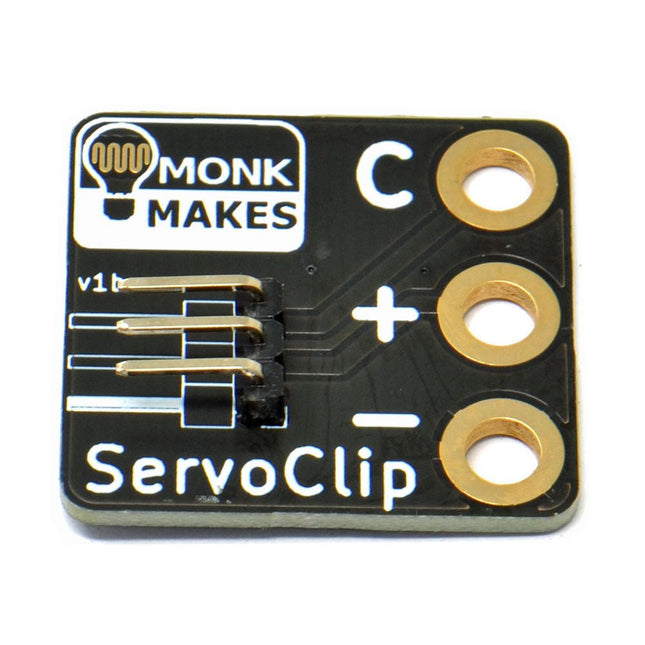
An adapter for connecting a servo meter with croc/alligator clips.
This is a handy little clip to connect a servo motor with 5.4 mm header socket using alligator clips. It is ideal for use with boards like the BBC micro:bit and Adafruit's Circuit Playground Express or Gemma.
Width: 27 mm
Height: 35 mm
Downloads
Datasheet
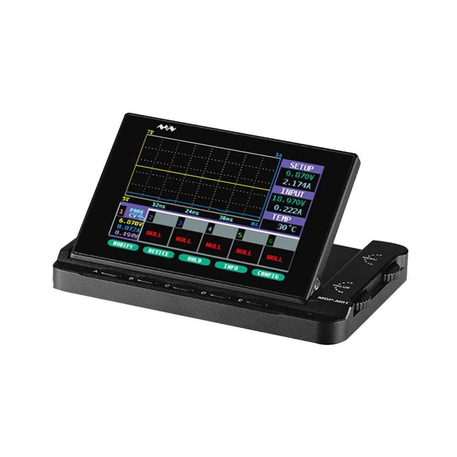
MDP-M01 is a display control module equipped with a 2.8-inch TFT display screen, the screen can be turned 90 degrees, which is convenient for users to view data and waveform. MDP-M01 can realize online display and control with MDP-P906 mini digital power supply modules and other modules of MDP system through 2.4 GHz wireless communication, and can control up to 6 sub-modules at the same time.
Specifications
Screen size
2.8" TFT
Screen resolution
240 x 320
Power
Micro USB power input, or taking power from sub-module via dedicated power cable
Input
DC 5 V/0.3 A
Other functions
Can control up to 6 sub-modulesUpgrade firmware through Micro USB
Dimensions
107 x 66 x 13.6 mm
Weight
133 g
Included
1x MDP-M01 Smart Digital Monitor
1x Cable (2.5 mm jack to Micro USB)
Downloads
User Manual v3.4
Firmware v1.32
The Arduino MKR Zero is a development board for music makers! With an SD card holder and dedicated SPI interfaces (SPI1), you are able to play music files without extra hardware.
The MKR Zero brings you the power of a Zero in the smaller format established by the MKR form factor. The MKR Zero board acts as a great educational tool for learning about 32-bit application development. It has an on-board SD connector with dedicated SPI interfaces (SPI1) that allows you to play with MUSIC files with no extra hardware! The board is powered by Atmel’s SAMD21 MCU, which features a 32-bit ARM Cortex M0+ core.
The board contains everything needed to support the microcontroller; simply connect it to a computer with a micro-USB cable or power it by a LiPo battery. The battery voltage can also be monitored since a connection between the battery and the analog converter of the board exists.
Specifications
Microcontroller
SAMD21 ARM Cortex-M0+ 32-bit low power
Board power supply (USB/VIN)
5 V
Supported battery
Li-Po single cell, 3.7 V, 700 mAh minimum
DC current for 3.3 V pin
600 mA
DC current for 5 V pin
600 mA
Circuit operating voltage
3.3 V
Digital I/O pins
22
PWM pins
12 (0, 1, 2, 3, 4, 5, 6, 7, 8, 10, A3 - or 18 -, A4 -or 19)
UART
1
SPI
1
I²C
1
Analog input pins
7 (ADC 8/10/12 bit)
Analog output pins
1 (DAC 10 bit)
External interrupts
10 (0, 1, 4, 5, 6, 7, 8, A1 -or 16-, A2 - or 17)
DC current per I/O pin
7 mA
Flash memory
256 KB
Flash memory for bootloader
8 KB
SRAM
32 KB
EEPROM
No
Clock speed
32.768 kHz (RTC), 48 MHz
LED_BUILTIN
32
Downloads
Datasheet
Eagle Files
Schematics
Fritzing
Pinout
SMA Straight Plug to SMA Straight Plug, 76.2 mm
Specifications
Frequency range
0 to 18 GHz VSWR (≤1.35)
Insertion loss
≤0,22 db
Body
Brass Nickel
Centre contact
Brass Gold
Insulator
PTFE
Ever wanted an automated house? Or a smart garden? Well, now it’s easy with the Arduino IoT Cloud compatible boards. It means: you can connect devices, visualize data, control and share your projects from anywhere in the world. Whether you’re a beginner or a pro, we have a wide range of plans to make sure you get the features you need.
Connect your sensors and actuators over long distances harnessing the power of the LoRa wireless protocol or throughout LoRaWAN networks.
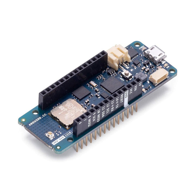
The Arduino MKR WAN 1310 board provides a practical and cost effective solution to add LoRa connectivity to projects requiring low power. This open source board can be connected to the Arduino IoT Cloud.
Better and More Efficient
The MKR WAN 1310, brings in a series of improvements when compared to its predecessor, the MKR WAN 1300. While still based on the Microchip SAMD21 low power processor, the Murata CMWX1ZZABZ LoRa module, and the MKR family’s characteristic crypto chip (the ECC508), the MKR WAN 1310 includes a new battery charger, a 2 MByte SPI Flash, and improved control of the board’s power consumption.
Improved Battery Power
The latest modifications have considerably improved the battery life on the MKR WAN 1310. When properly configured, the power consumption is now as low as 104 uA! It is also possible to use the USB port to supply power (5 V) to the board; run the board with or without batteries – the choice is yours.
On-board Storage
Data logging and other OTA (Over The Air) functions are now possible since the inclusion of the on board 2 MByte Flash. This new exciting feature will let you transfer configuration files from the infrastructure onto the board, create your own scripting commands, or simply store data locally to send it whenever the connectivity is best. Whilst the MKR WAN 1310’s crypto chip adds further security by storing credentials & certificates in the embedded secure element.
These features make it the perfect IoT node and building block for low-power wide-area IoT devices.
Specifications
The Arduino MKR WAN 1310 is based on the SAMD21 microcontroller.
Microcontroller
SAMD21 Cortex-M0+ 32-bit low power ARM MCU (datasheet)
Radio module
CMWX1ZZABZ (datasheet)
Board power supply (USB/VIN)
5 V
Secure element
ATECC508 (datasheet)
Supported batteries
Rechargeable Li-Ion, or Li-Po, 1024 mAh minimum capacity
Circuit operating voltage
3.3 V
Digital I/O pins
8
PWM pins
13 (0 .. 8, 10, 12, 18 / A3, 19 / A4)
UART
1
SPI
1
I²C
1
Analog input pins
7 (ADC 8/10/12 bit)
Analog output pins
1 (DAC 10 bit)
External interrupts
8 (0, 1, 4, 5, 6, 7, 8, 16 / A1, 17 / A2)
DC current per I/O pin
7 mA
CPU flash memory
256 KB (internal)
QSPI flash memory
2 MByte (external)
SRAM
32 KB
EEPROM
No
Clock speed
32.768 kHz (RTC), 48 MHz
LED_BUILTIN
6
USB
Full-Speed USB Device and embedded Host
Antenna gain
2 dB (bundled pentaband antenna)
Carrier frequency
433/868/915 MHz
Dimensions
67.64 x 25 mm
Weight
32 g
Downloads
Eagle Files
Schematics
Fritzing
Pinout
Elektor GREEN and GOLD members can download their digital edition here.
Not a member yet? Click here.
ESP32 Audio Transceiver Board (Part 2)Wireless Audio Transmission
Inductive AM TransmitterUses Pico’s PIO in an Arduino Sketch
Navigating Wireless ProtocolsA Technical Guide
Satellite Tracking Using LoRaThe TinyGS Network Bringing Space Data to Earth
4G-Compatible SMS Remote ControlRemotely Control Your Equipment
High-Speed ProbeHigh-Impedance Inputs for Signals up to 200 MHz
From Life’s ExperienceKafka
KrakenSDR
Performance Tests with the RP2350Is an Upgrade from Raspberry Pi Pico 1 to Pico 2 Worthwhile?
Contact-Free E-Field Measurements (2)A Laser Vibrometer for Assessing the Membrane's Vibrations
Crystals and OscillatorsImproving Crystal Accuracy Through Capacitor Selection
Starting Out in ElectronicsSpecial Audio ICs
Getting Started with Coding a DIY Project
SPECTRAN® V6 MobileModular, Configurable Real-Time Spectrum Analyzer for Reliable Measurements Across All Frequency Ranges
The Future of AI Is Forged in SiliconAn Interview with Anastasiia Nosova
Autonomous Sensor Node v2.0 (System Architecture)Solar-Powered Sensing Platform with Integrated GPS, LoRaWAN, and More
Precise PositioningBluetooth Channel Sounding Tested
Powering the Future of Wireless CommunicationBTRY’s Ultra-Thin Solid-State Batteries
Test-Driven Development in Firmware Writing
Phone-Controlled Model CarWi-Fi + ESP32 + Smartphone = Remote Control
2025: An AI OdysseyAI Reasoning Models: The Chain-of-Thought Revolution
Solar Charge Controller with MPP Tracking (3)Software and Commissioning
Raspberry Pi Zero Web Streaming CameraUsing the ZeroTier VPN
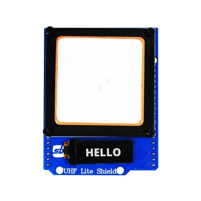
Designed with cutting-edge technology, this shield brings the power of Ultra High Frequency (UHF) RFID to your fingertips.
With the Ardi UHF Shield, you can effortlessly read up to an impressive 50 tags per second, allowing for fast and efficient data collection. The shield features an onboard UHF antenna, ensuring reliable and accurate tag detection even in challenging environments.
Equipped with a high-performance 0.91" OLED display, the Ardi UHF Shield provides clear and concise visual feedback, making it easy to monitor and interact with the RFID readings. Whether you're tracking inventory, managing access control, or implementing a smart attendance system, this shield has you covered.
With a remarkable 1-meter reading distance, the Ardi UHF Shield offers an extended range for capturing RFID data. Say goodbye to the limitations of proximity-based RFID systems and embrace the flexibility and convenience of a wider reading range.
The shield provides read-write capabilities, allowing you to not only retrieve information from RFID tags but also update or modify data as needed. This versatility opens up a world of possibilities for advanced applications and custom solutions.
Features
Onboard High-performance UHF RFID reader module
24 hours x 365 days’ work normally
0.91” OLED display for visual interaction with shield
Multi-tone Buzzer onboard for Audio alerts
Shield compatible with both 3.3 V and 5 V MCU
Mounts directly onto ArdiPi, Ardi32 or other Arduino compatible boards
Specifications
OLED resolution 128x32 pixels
I²C Interface for OLED
UHF Frequency Range (EU/UK): 865.1-867.9 MHz
UHF Module Type: Read/Write
Protocols Supported: EPCglobal UHF Class 1 Gen 2 / ISO 18000-6C
Reading Distance: 1 meters
Can identify over 50 tags simultaneously
Communication interface: TTL UART Interface for UHF
Communication baud rate: 115200 bps (default and recommend) – 38400 bps
Operation current: 180 mA @ 3.5 V (26 dBm Output, 25°C), 110 mA @ 3.5 V (18 dBm Output, 25°C)
Working humidity <95% (+25°C)
Heat-dissipating method Air cooling(no need out install cooling fin)
Tags storage capacity: 200 pcs tags @ 96 bit EPC
Output power: 18-26 dBm
Output power accuracy: +/-1 dB
Tags RSSI support
The OWON SPS3081 Fanless Programmable DC Power Supply (120 W) delivers ultra-quiet, high-precision performance with 10 mV/1 mA accuracy and advanced heat dissipation for long-term reliability. Featuring comprehensive protection, a USB interface with SCPI support for remote control, and a 2.8-inch TFT LCD screen, it is the perfect choice for laboratories, electronics testing, and research.
Features
Fanless design: Ultra-quiet operation, reducing vibration noise and minimizing the potential failure risks associated with traditional cooling fans.
Excellent heat dissipation design: Ensures a controlled temperature rise, allowing long-term operation under full load conditions and extending internal component longevity.
Lightweight and ultra-thin design.
Output accuracy up to 10 mV/1 mA.
Supports List waveform editing and output, with four memory shortcut parameters for quick and convenient access.
Integrated protection features include overvoltage, overcurrent, overtemperature, and input undervoltage protection for enhanced safety.
Built-in discharge circuit prevents residual high voltage risks when the power is turned off.
USB communication interface with SCPI protocol support, enabling PC programming and remote control for simplified user management.
2.8-inch TFT LCD screen
Specifications
Model
SPS6051
SPS3081
Rated Output (0°C-40°C)
Voltage
0-61 V
0-31 V
Current
0-5.1 A
0-8.1 A
Power
150 W
120 W
Load Regulation
Voltage
≤30 mV
Current
≤20 mA
Power Regulation
Voltage
≤30 mV
Current
≤20 mA
Setting Resolution
Voltage
10 mV
Current
1 mA
Readback Resolution
Voltage
10 mV
Current
1 mA
Seting Accuracy (25°C ±5°C)
Voltage
≤0.05% ±20 mV
≤0.1% ±20 mV
Current
≤0.05% ±20 mA
≤0.2% ±20 mA
Readback Accuracy (25°C ±5°C)
Current
≤0.05% ±20 mV
≤0.1% ±20 mV
Voltage
≤0.05% ±20 mV
≤0.2% ±20 mA
Ripple/Noise
Voltage
≤30 mVp-p
≤30 mVp-p
Voltage
≤4 mVrms
≤5 mVrms
Current
≤10 mAp-p
≤30 mAp-p
Output temperature coefficient (0°C-40°C)
Voltage
100 ppm/°C
Current
200 ppm/°C
Readback temperature coefficient
Voltage
100 ppm/°C
Current
200 ppm/°C
Response Time (50-100% rated load)
≤1.0 ms
Storage
4 groups of data
Working Temperature
0-40°C
Display
2.8-inch color LCD display
Interface
USB
Dimensions (W x H x D)
82 x 142 x 226 mm
Weight
1.8 kg
Included
1x OWON SPS3081 Power Supply
2x Test leads
1x Power cord
1x Manual
Downloads
Datasheet
User Manual
Programming Manual
PC Software
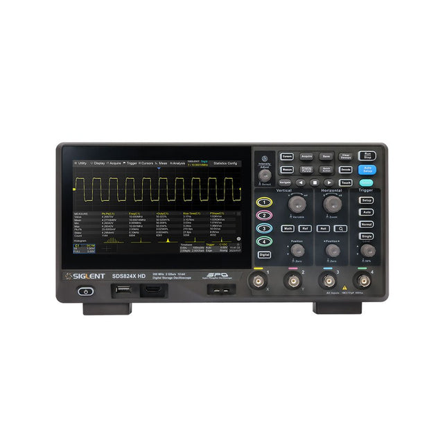
The Siglent SDS814X HD digital storage oscilloscope is based on 2 GSa/s, 12-bit Analog-Digital Converters and front ends with excellent noise floor performance. With a 100 MHz bandwidth, and a maximum record length of 50 Mpts, and the capability to analyze 4 analog channels alongside 16 digital channels, the SDS814X HD is perfectly suited for mixed signal analysis.
Features
12-bit High Resolution
12-bit Analog-Digital Convertors with sample rate up to 2 GSa/s
Front ends with 70 μVrms noise floor @ 100 MHz bandwidth
2/4 analog channels, up to 700 MHz bandwidth
SPO technology
Waveform capture rate up to 80,000 wfm/s (normal mode), and 500,000 wfm/s (sequence mode)
Supports 256-level intensity grading and color temperature display modes.
Up to 50 Mpts record length
Digital trigger system
Intelligent trigger: Edge, Slope, Pulse width, Window, Runt, Interval, Dropout, Pattern, Video (HDTV supported), Qualified, Nth edge, Delay, Setup/Hold time.
Serial bus triggering and decoder, supports protocols I²C, SPI, UART, CAN, LIN.
Segmented acquisition (Sequence) mode, dividing the maximum record length into multiple segments (up to 80,000), according to trigger conditions set by the user, with a very small dead time between segments to capture the qualifying event.
History waveform record (History) function, the maximum recorded waveform length is 80,000 frames.
Automatic measurements on 50+ parameters, supports statistics with histogram, track, trend, Gating measurement, and measurements on Math, History and Ref.
4 Math traces (2 Mpts FFT, addition, subtraction, multiplication, division, integration, differential, square root, etc.), supports formula editor.
Abundant data analysis functions such as Search, Navigate, Counter, Bode plot and Power Analysis
High Speed hardware-based Mask Test function, with Mask Editor tool for creating user-defined masks
16 digital channels (optional)
25 MHz waveform generator (optional)
7" TFT-LCD display with 1024 x 600 resolution; Capacitive touch screen supports multi-touch gestures.
Interfaces include: USB Hosts, USB Device (USBTMC), LAN (VXI-11/Telnet/Socket), Pass/Fail, Trigger Out
Built-in web server supports remote control over the LAN port using a web browser. Supports SCPI remote control commands. Supports external mouse and keyboard. Supports NTP.
Specifications
Analog Channels
4
Bandwidth
100 MHz
Vertical resolution
12-bit
Sample rate (Max.)
One channel mode: 2 GSa/sTwo channel mode: 1 GSa/sFour channel mode: 500 MSa/s
Memory depth (Max.)
One channel mode: 50 Mpts/chTwo channel mode: 25 Mpts/chFour channel mode: 10Mpts/ch
Waveform capture rate (Max.)
Normal mode: 80,000 wfm/sSequence mode: 500,000 wfm/s
Trigger type
Edge, Slope, Pulse width, Window, Runt, Interval, Dropout, Pattern, Video, Qualified, Nth edge, Delay, Setup/Hold time, Serial
Serial trigger and decode (Standard)
I²C, SPI, UART, CAN, LIN
Measurement
50+ parameters, statistics, histogram, trend, and track supported
Math
4 traces 2 Mpts FFT, Filter, +, -, x, ÷, ∫dt, d/dt, √, Identity, Negation, Absolute, Sign, ex, 10x, ln, lg, Interpolation, MaxHold, MinHold, ERES, Average. Supports formula editor
Data analysis
Search, Navigate, History, Mask Test, Counter, Bode plot, and Power Analysis
Digital channel (optional)
16-channel; maximum sample rate up to 1 GSa/s; record length up to 10 Mpts
USB AWG module (option)
One channel, 25 MHz, sample rate of 125 MHz, wave length of 16 kpts, isolated output
I/O
2x USB 2.0 Host, USB 2.0 Device, 10/100 M LAN, Auxiliary output (TRIG OUT, PASS/FAIL), SBUS (Siglent MSO)
Probe (Standard)
Passive probe PB470 for each channel
Display
7 TFT-LCD with capacitive touch screen (1024x600)
Included
1x Siglent SDS814X Oscilloscope
4x Passive probe (100 MHz) PP510
1x Power cord (EU)
1x USB cable
1x Certificate of calibration
1x Quick start
Downloads
Datasheet
Manual
Programming guide
With 20+ Practical Projects in Logic and Circuit Design
This book is a practical guide to digital electronics, covering the essential components of modern digital systems: number systems, logic gates, Boolean algebra, combinational and sequential logic, and more.
Through more than 20 structured projects, you’ll design and build digital systems using real-world components such as logic gates, multiplexers, decoders, flip-flops, counters, and shift registers. The projects range from basic LED logic circuits to digital locks, display systems, traffic light controllers, and timing-based designs.
Selected projects introduce the use of tools such as CircuitVerse for circuit simulation, while several designs make use of 74HC-series logic devices, commonly used in digital hardware prototyping.
Inside, you’ll find:
Clear coverage of number systems and binary arithmetic
Logic gate fundamentals and universal gate implementations
Step-by-step projects using flip-flops, counters, and registers
Real-world design with 74HC-series logic chips
Techniques for designing combinational and sequential systems
This book takes a design-first, application-driven approach to digital electronics—built around working circuits, tested logic, and hands-on experimentation.