ESP32-C3-WROOM-02U is a general-purpose Wi-Fi and Bluetooth LE module. The rich set of peripherals and high performance make the module an ideal choice for smart homes, industrial automation, health care, consumer electronics, etc. ESP32-C3-WROOM-02U features an external SPI flash and comes with a connector for an external antenna. ESP32-C3-WROOM-02U has an operating ambient temperature option of –40∼85°C, embedded with the ESP32-C3 chip. ESP32-C3 has a 32-bit RISC-V single-core processor. It integrates a rich set of peripherals, ranging from UART, I²C, I²S, remote control peripheral, LED PWM controller, general DMA controller, TWAI controller, USB Serial/JTAG controller, temperature sensor, ADC, etc. It also includes SPI, Dual SPI and Quad SPI interfaces. Features Flash: 4 MB (Quad SPI) Dimensions: 18.0 x 20.0 x 3.2 mm Downloads Datasheet
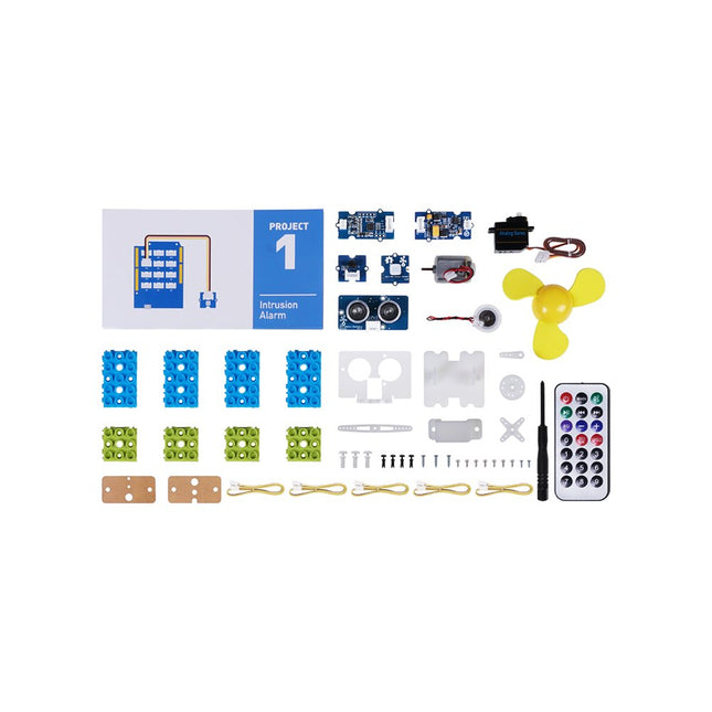
This is an add-on kit for the Seeed Studio Grove Beginner Kit for Arduino.
Applications
Suitable for Arduino beginners
Suitable for infrared control and motion detect
Suitable for getting started with open-source hardware and Arduino coding
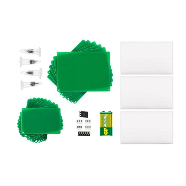
Included
1x Grove Water Atomization
1x Grove Mini Fan
1x Grove Servo
1x Grove Ultrasonic Distance Sensor
1x Grove Infrared Receiver
1x Grove Mini PIR Motion Sensor
1x Grove Green Wrapper
1x Grove Blue Wrapper
5x Grove Cable
1x Infrared Remote Control Key
1x Ultrasonic Sensor Bracket Set
1x Motor Bracket Set
1x Servo Base
Reinforcing its commitment to widening the accessibility to and innovation in the area of deep learning, NVIDIA has created a free, self-paced, online Deep Learning Institute (DLI) course, “Getting Started on AI with Jetson Nano.” The course's goal is to build foundational skills to enable anyone to get creative with the Jetson Developer Kit. Please be aware that this kit is for those who already own a Jetson Nano Developer Kit and want to join the DLI Course. A Jetson Nano is not included in this kit.
Included in this kit is everything you will need to get started in the “Getting Started on AI with Jetson Nano” (except for a Jetson Nano, of course), and you will learn how to
Set up your Jetson Nano and camera
Collect image data for classification models
Annotate image data for regression models
Train a neural network on your data to create your own models
Run inference on the Jetson Nano with the models you create
The NVIDIA Deep Learning Institute offers hands-on training in AI and accelerated computing to solve real-world problems. Developers, data scientists, researchers, and students can get practical experience powered by GPUs in the cloud and earn a competency certificate to support professional growth. They offer self-paced, online training for individuals, instructor-led workshops for teams, and downloadable course materials for university educators.
Included
32 GB microSD Card
Logitech C270 Webcam
Power Supply 5 V, 4 A
USB Cable - microB (Reversible)
2-Pin Jumper
Please note: Jetson Nano Developer Kit not included.
TapNLink modules provide wireless interfaces for linking electronic systems to mobile devices and the Cloud. TapNLink connects directly to the target system's microcontroller. It integrates into and is powered by the target system. All TapNLink products are easily configured to control access by different types of users to data in the target system.
TapNLink facilitates rapid creation of Human Machine Interfaces (HMI) that run on Android, iOS and Windows mobiles. HMI apps are easily customized for different users and can be deployed and updated to keep pace with evolving system requirements and user needs.
TapNLink Wi-Fi modules can also be configured to connect the target system permanently to a wireless network and the Cloud. This enables permanent logging of target system data and alarms.
Features
Wireless Channels
Wi-Fi 802.11b/g/n
Bluetooth Low Energy (BLE 4.2)
Near Field Communication (NFC) Type5 tag (ISO/IEC 15693)
Supported Target Connections: Connects on 2 GPIO of the target microcontroller and supports:
Serial interface with Software Secure Serial Port (S3P) protocol
Serial interface with ARM SWD debug protocol.
UART with Modbus protocol
Mobile Platform Support
HTML5 web apps (Android, iOS)
API for Cordova (Android, iOS, Windows 10)
Java (Android, iOS native)
Auto-app generator for Android and iOS mobiles
Security
Configurable access profiles
Configurable, encrypted passwords
AES-128/256 module-level data encryption
Configurable secure pairing with NFC
Dimensions: 38 mm x 28 mm x 3 mm
Electrical Characteristics
Input voltage: 2.3V to 3.6 V
Low power consumption:
Standby: 100 µA
NFC Tx/Rx: 7 mA
Wi-Fi Rx: 110 mA
Wi-Fi Tx : 280 mA (802.11b)
Temperature Range: -20°C ~ +55°C
Compliance
CE (Europe), FCC (USA), IC (Canada)
REACH
RoHS
WEEE
Ordering Information
Base Part Number: TnL-FIW103
MOQ: 20 modules
TapNLink modules pre-qualified, pre-programmed and ready to configure.
IoTize Studio configuration and testing software
Software for HMI on mobile devices (iOS, Android, Windows 10)
IoTize Cloud MQTT infrastructure (open source)
For more information, check out the datasheet here.
Elektor GREEN and GOLD members can download their digital edition here.
Not a member yet? Click here.
Relio v1.0 - Presence Detection and Remote ControlA Matter-Enabled Smart Controller for AC Appliances
Designing Better PCBsA Practical Guide for Professionals and Makers
KiCad 9Top New and Updated Features
Precision Picoammeter (1)With Curve Tracer Functionality Down to the pA range!
Christmas Star 2025A Star Is Soldered
100 mV Continuity Tester
Who’s Pushing the Boundaries of European Electronics?Companies to Watch
productronica 2025: What’s New in Electronics Development and Production
Automation to Tackle Reshoring Manufacturing, Tariffs and Labour Shortages
Beyond Future ProofCircularity in Electronics
Passive ComponentsLow-Loss Inductors Enabling High-Efficiency DC/DC Converters
How Desktop Manufacturing Machines Are Democratizing PCB Production
Starting Out in Electronics...Needs Power
UHD Displays Driven with EaseYour Guide to Easily Put Various TFT-LCDs Into Operation Quickly
Soldering in 2025Practical Soldering Tips Straight from the Workbench
SimulIDEAn All-in-One Tool for Circuit Prototyping
2025: An AI OdysseyFrom Autocomplete to Colleague
Wordy Christmas TreeA Festive Electronics Project with a Linguistic Twist
Err-lectronicsCorrections, Updates, and Readers’ Letters
Analog Pipeline DistortionA Cool Audio Effect For Guitars and Other Instruments
ESP32 Audio Transceiver Board (Part 3)Stereo Transmission and Dual Radio
With 20+ Practical Projects in Logic and Circuit Design
This book is a practical guide to digital electronics, covering the essential components of modern digital systems: number systems, logic gates, Boolean algebra, combinational and sequential logic, and more.
Through more than 20 structured projects, you’ll design and build digital systems using real-world components such as logic gates, multiplexers, decoders, flip-flops, counters, and shift registers. The projects range from basic LED logic circuits to digital locks, display systems, traffic light controllers, and timing-based designs.
Selected projects introduce the use of tools such as CircuitVerse for circuit simulation, while several designs make use of 74HC-series logic devices, commonly used in digital hardware prototyping.
Inside, you’ll find:
Clear coverage of number systems and binary arithmetic
Logic gate fundamentals and universal gate implementations
Step-by-step projects using flip-flops, counters, and registers
Real-world design with 74HC-series logic chips
Techniques for designing combinational and sequential systems
This book takes a design-first, application-driven approach to digital electronics—built around working circuits, tested logic, and hands-on experimentation.
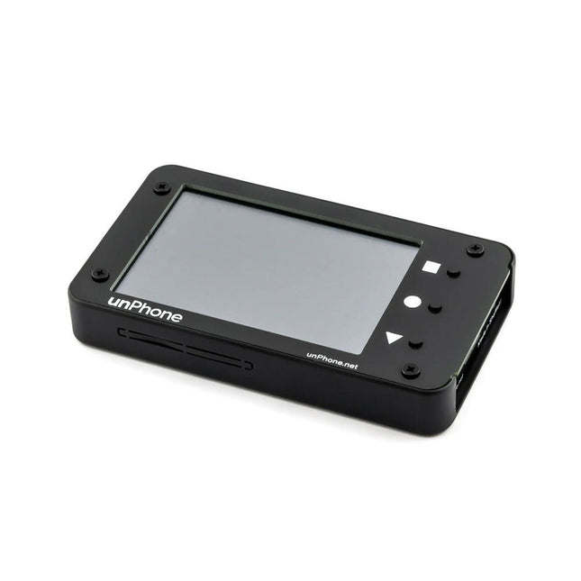
The unPhone is an open-source IoT development platform powered by the ESP32S3 microcontroller. It features integrated LoRa, Wi-Fi, and Bluetooth connectivity, a touchscreen, and a LiPo battery, offering a robust and versatile solution for IoT development. Its compatibility with Adafruit's FeatherWing standard enables easy expansion, making it an ideal choice for educators, makers, and developers seeking a flexible and user-friendly platform.
Features
ESP32S3 microcontroller (with 8 MB flash and 8 MB PSRAM)
LoRaWAN licence-free radio communication (plus the ESP32's excellent wifi and bluetooth support)
3.5" (320 x 480) LCD capacitive touchscreen for easy debugging and UI creation
IR LEDs for surreptitiously switching the cafe TV off
1200 mAh LiPo battery with USB-C charging
Vibration motor for notifications
Compass/Accelorometer
A robust case
SD card slot
Power and reset buttons
Programmable in C++ or CircuitPython
Expander board that supports two Featherwing sockets and a prototyping area
Open source firmware compatible with the Arduino IDE, PlatformIO and Espressif's IDF development framework
Included
unPhone (assembled)
Expander board
FPC cable (to link the expander board to unPhone)
Self adhesive mounts for the expander board
Code Examples
C++ library
Kick the tyres on everything in the box
The main LVGL demo
CircuitPython
Support forum
Textbook (especially chapter 11)
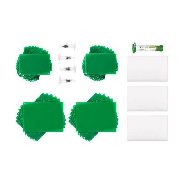
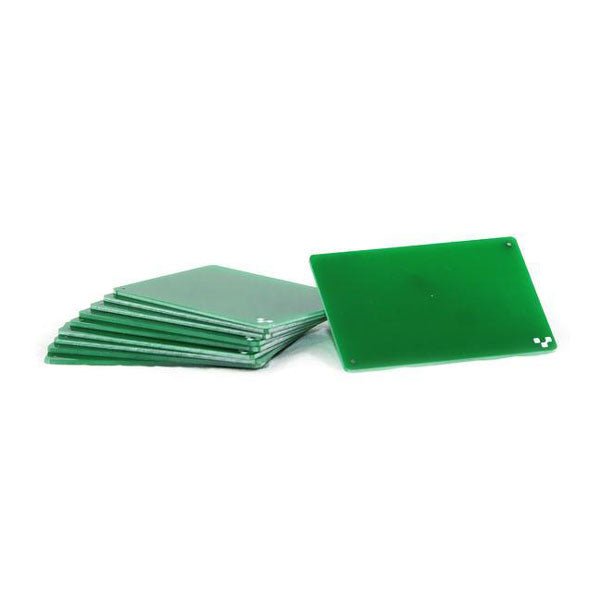
If you are going to be drilling, we recommend drilling on FR1 substrates. Unlike FR4, FR1 dust does not contain fiber glass. It is also a softer material, which means a less wear and tear on the drill bits. Download the template and incorporate them into your design here. 10 substrates included.
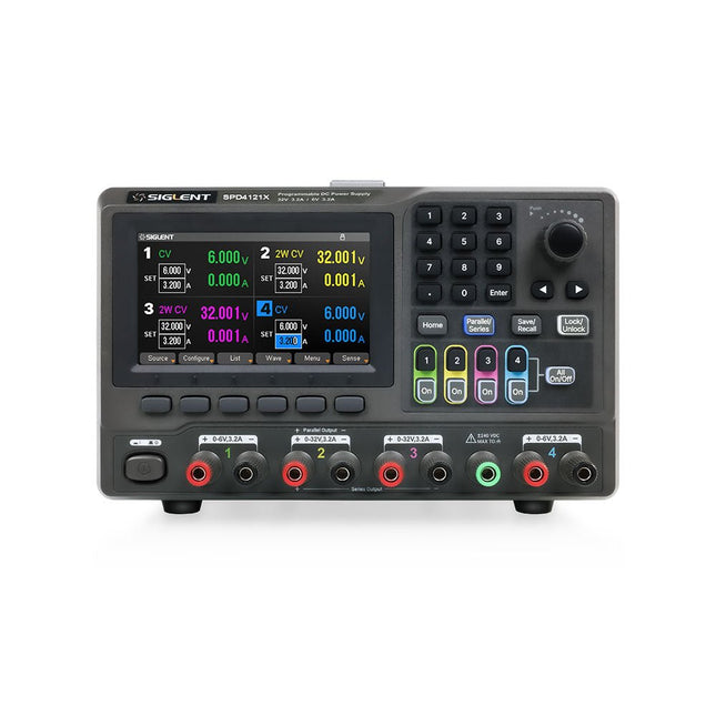
The Siglent SPD4121X is a 4-channel DC Linear Programmable Power Supply equipped with a 4.3-inch TFT-LCD display, friendly human-machine interface, and excellent performance indicators. Real-time waveform display provides engineers with an informative user interface.
SPD4121X offers a total output power of 285 W with a resolution of 1 mV/1 mA. The maximum voltage and current for each channel are as follows:
CH1: 15 V/1.5 A
CH2: 12 V/10 A
CH3: 12 V/10 A
CH4: 15 V/1.5 A
Features
Rated output power: 285 W
Rated voltage: 32 V, 12 V, 30 V
Up to four high-precision power supplies with independent controllable outputs, supporting CH2 and CH3 series and parallel connections
Clear graphical interface with waveform and timer display modes
5-digit voltage and current display with minimum resolution of 1 mV, 1 mA
Fast output response time: <50us
The high current channel support remote voltage compensation sense function. The maximum compensation voltage is 0.6 V
Overvoltage protection and overcurrent protection or safe and accurate operation
Equipped with a 4.3-inch TFT-LCD display (480 x 272 resolution)
USB and LAN standard communication
USB-GPIB module is optional
Excellent channel density with up to 4 channels in a 3U half rack package
Internal data storage for setups and parameters
Embedded Web Server with instrument communication that doesn’t require software installation
Fully SCPI programming command set support as well as a LabView driver for remote control and system automation
Specifications
SPD4323X
SPD4121X
SPD4306X
Channel Output
CH1: Voltage 0 to 6 V Current 0 to 3.2 ACH2: Voltage 0 to 32 V Current 0 to 3.2 ACH3: Voltage 0 to 32 V Current 0 to 3.2 ACH4: Voltage 0 to 6 V Current 0 to 3.2 A
CH1: Voltage 0 to 15 V Current 0 to 1.5 ACH2: Voltage 0 to 12 V Current 0 to 10 ACH3: Voltage 0 to 12 V Current 0 to 10 ACH4: Voltage 0 to 15 V Current 0 to 1.5 A
CH1: Voltage 0 to 15 V Current 0 to 1.5 ACH2: Voltage 0 to 30 V Current 0 to 6 ACH3: Voltage 0 to 30 V Current 0 to 6 ACH4: Voltage 0 to 15 V Current 0 to 1 A
Resolution
1 mV, 1 mA
1 mV, 1 mA
1 mV, 1 mA
Setting Accuracy
Voltage: ±(0.03% of reading+10) mV, Current: ±(0.3% of reading+10) mA
Voltage: ±(0.03% of reading+10) mV, Current: ±(0.3% of reading+10) mA
Voltage: ±(0.03% of reading+10) mV, Current: ±(0.3% of reading+10) mA
Readback Accuracy
Voltage: ±(0.03% of reading+10) mV, Current: ±(0.3% of reading+10) mA
Voltage: ±(0.03% of reading+10) mV, Current: ±(0.3% of reading+10) mA
Voltage: ±(0.03% of reading+10) mV, Current: ±(0.3% of reading+10) mA
Display
4.3" TFT-LCD 5-digit voltage and current display
4.3" TFT-LCD 5-digit voltage and current display
4.3" TFT-LCD 5-digit voltage and current display
Output power
240 W
285 W
400 W
Included
1x Siglent SPD4121X Power Supply
1x Power cord (EU)
1x Output test cord (3 A)
1x USB cable
1x Quick start guide
Downloads
Datasheet
Manual
Quick start
The Siglent SPD4306X is a 4-channel DC Linear Programmable Power Supply equipped with a 4.3-inch TFT-LCD display, friendly human-machine interface, and excellent performance indicators. Real-time waveform display provides engineers with an informative user interface.
SPD4306X offers a total output power of 400 W with a resolution of 1 mV/1 mA. The maximum voltage and current for each channel are as follows:
CH1: 15 V/1.5 A
CH2: 30 V/6 A
CH3: 30 V/6 A
CH4: 15 V/1 A
Features
Rated output power: 400 W
Rated voltage: 32 V, 12 V, 30 V
Up to four high-precision power supplies with independent controllable outputs, supporting CH2 and CH3 series and parallel connections
Clear graphical interface with waveform and timer display modes
5-digit voltage and current display with minimum resolution of 1 mV, 1 mA
Fast output response time: <50us
The high current channel support remote voltage compensation sense function. The maximum compensation voltage is 0.6 V
Overvoltage protection and overcurrent protection or safe and accurate operation
Equipped with a 4.3-inch TFT-LCD display (480 x 272 resolution)
USB and LAN standard communication
USB-GPIB module is optional
Excellent channel density with up to 4 channels in a 3U half rack package
Internal data storage for setups and parameters
Embedded Web Server with instrument communication that doesn’t require software installation
Fully SCPI programming command set support as well as a LabView driver for remote control and system automation
Specifications
SPD4323X
SPD4121X
SPD4306X
Channel Output
CH1: Voltage 0 to 6 V Current 0 to 3.2 ACH2: Voltage 0 to 32 V Current 0 to 3.2 ACH3: Voltage 0 to 32 V Current 0 to 3.2 ACH4: Voltage 0 to 6 V Current 0 to 3.2 A
CH1: Voltage 0 to 15 V Current 0 to 1.5 ACH2: Voltage 0 to 12 V Current 0 to 10 ACH3: Voltage 0 to 12 V Current 0 to 10 ACH4: Voltage 0 to 15 V Current 0 to 1.5 A
CH1: Voltage 0 to 15 V Current 0 to 1.5 ACH2: Voltage 0 to 30 V Current 0 to 6 ACH3: Voltage 0 to 30 V Current 0 to 6 ACH4: Voltage 0 to 15 V Current 0 to 1 A
Resolution
1 mV, 1 mA
1 mV, 1 mA
1 mV, 1 mA
Setting Accuracy
Voltage: ±(0.03% of reading+10) mV, Current: ±(0.3% of reading+10) mA
Voltage: ±(0.03% of reading+10) mV, Current: ±(0.3% of reading+10) mA
Voltage: ±(0.03% of reading+10) mV, Current: ±(0.3% of reading+10) mA
Readback Accuracy
Voltage: ±(0.03% of reading+10) mV, Current: ±(0.3% of reading+10) mA
Voltage: ±(0.03% of reading+10) mV, Current: ±(0.3% of reading+10) mA
Voltage: ±(0.03% of reading+10) mV, Current: ±(0.3% of reading+10) mA
Display
4.3" TFT-LCD 5-digit voltage and current display
4.3" TFT-LCD 5-digit voltage and current display
4.3" TFT-LCD 5-digit voltage and current display
Output power
240 W
285 W
400 W
Included
1x Siglent SPD4306X Power Supply
1x Power cord (EU)
1x Output test cord (3 A)
1x USB cable
1x Quick start guide
Downloads
Datasheet
Manual
Quick start
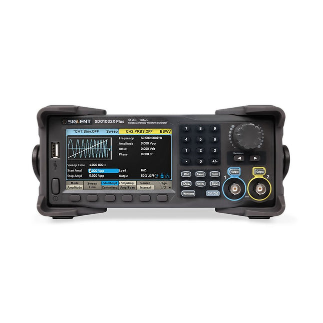
The Siglent SDG1032X Plus is a high-performance dual-channel function/arbitrary waveform generator with a 30 MHz max frequency, 16-bit resolution, and 1 GSa/s sampling rate for superior signal fidelity.
It features TrueArb for low-distortion waveforms, EasyPulse for jitter-free pulses, and robust sequence playback. With ±10 V amplitude, a 4.3" display, and versatile modulation, it's a reliable choice for engineers and researchers.
Features
Dual Channels: Independent output with maximum frequency of 30 MHz
High Sampling Rate: 1 GSa/s for precise waveform generation
High Vertical Resolution: 16-bit resolution for accurate signal reproduction
TrueArb Technology: Generates low-distortion arbitrary waveforms with high fidelity
EasyPulse Technology: Produces jitter-free square and pulse signals with fine control over rise/fall times
Arbitrary Waveform Length: Supports up to 8 Mpts per channel for complex waveform design
Wide Amplitude Range: ±10 V maximum output amplitude
Built-in Modulation Functions: AM, FM, PM, PWM, PSK, FSK, ASK, and more
Multi-Pulse Output: Enables measurement of power equipment switching parameters
PRBS Pattern Generation: Supports up to 40 Mbps for advanced testing needs
Sweep and Burst Modes: Flexible test capabilities with adjustable parameters
Sequence Playback Function: Stores and plays back complex waveforms efficiently
Frequency Counter: Measures frequencies up to 200 MHz with high precision
User-Friendly Display: 4.3" color LCD with a clear interface
Remote Control Support: Built-in WebServer for control via a web browser
Compact Design: Portable and space-saving form factor
Specifications
Bandwidth
30 MHz
Channels
2
Sampling rate
1 GSa/s (4x Interpolation)
Vertical resolution
16 bits (per channel)
Waveform length
8 Mpts
Max. amplitude
±10 V
Display
4.3" color TFT LCD (480 x 272)
Interfaces
USB Host, USB Device, LAN
Dimensions
260 x 107 x 296 mm
Weight
4.35 kg
Included
1x Siglent SDG1032X Plus Arbitrary Function Generator
1x Power Cord
1x USB Cable
1x Guarantee Card
1x Quick Start Guide
Downloads
Datasheet
User Manual
Programming Guide
Software
The reComputer J1020 v2 is a compact edge AI device powered by the NVIDIA Jetson Nano 4 GB production module, delivering 0.5 TFLOPs of AI performance. It features a robust aluminum case with a passive heatsink and comes pre-installed with JetPack 4.6.1. The device includes 16 GB of onboard eMMC storage and offers 2x SCI, 4x USB 3.0, M.2 Key M, HDMI, and DP.
Applications
Computer Vision
Machine Learning
Autonomous Mobile Robot (AMR)
Specifications
Jetson Nano 4 GB System-on-Module
AI Performance
Jetson Nano 4 GB (0.5 TOPS)
GPU
NVIDIA Maxwel architecture with 128 NVIDIA CUDA cores
CPU
Quad-core ARM Cortex-A57 MPCore processor
Memory
4 GB 64-bit LPDDR4 25.6 GB/s
Video Encoder
1x 4K30 | 2x 1080p60 | 4x 1080p30 | 4x 720p60 | 9x 720p30 (H.265 & H.264)
Video Decoder
1x 4K60 | 2x 4K30 | 4x 1080p60 | 8x 1080p30 | 9x 720p60 (H.265 & H.264)
Carrier Board
Storage
1x M.2 Key M PCIe
Networking
Ethernet
1x RJ-45 Gigabit Ethernet (10/100/1000M)
I/O
USB
4x USB 3.0 Type-A1x Micro-USB port for device mode
CSI Camera
2x CSI (2-lane 15-pin)
Display
1x HDMI Type A; 1x DP
Fan
1x 4-pin Fan Connector (5 V PWM)
CAN
1x CAN
Multifunctional Port
1x 40-Pin Expansion header
1x 12-Pin Control and UART header
Power Supply
DC 12 V/2 A
Mechanical
Dimensions
130 x 120 x 50 mm (with Case)
Installation
Desktop, wall-mounting
Operating Temperature
−10°C~60°C
Included
reComputer J1020 v2 (system installed)
12 V/2 A power adapter (with 5 interchangeable adapter plugs)
Downloads
reComputer J1020 v2 datasheet
reComputer J1020 v2 3D file
Seeed NVIDIA Jetson Product Catalog
NVIDIA Jetson Device and Carrier Boards Comparison
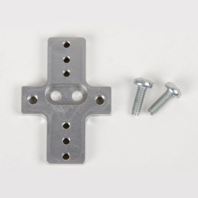
This rigid end effector plate is designed to be in place of the standard AxiDraw pen-lift Z stage, and provides an alternative mounting scheme for mounting various things to the end of the AxiDraw's arm, for applications where greater rigidity is important but the lifting ability of the standard Z stage is not required.
The rigid end effector is custom machined from aluminum, and provides six M3 tapped holes and two M4 tapped holes for mounting what ever it is that you would like to mount to the end of the AxiDraw, to use it as a 2D robot arm. The hole pattern is compatible with the AxiDraw pen clip, so you can, if you like, mount the AxiDraw's pen clip to this end effector.
Installation is straightforward, but requires a Pozidrive PZ2 screwdriver, not included*. Remove the AxiDraw's pen clip, and then remove the pen-lift Z stage by removing two screws with the PZ2 screwdriver. Install the rigid end effector plate in its place, using the two included mounting screws and the PZ2 screwdriver. You may wish to also tie back or fully remove the AxiDraw's cable guides, which normally extend to power the pen-lift stage.
Specifications
Material: Anodized 6061-T6 aluminum
Size: 1.97 x 1.38 x 0.19 inches (50 x 35 x 4.8 mm)
Weight: Approximately 11 g
Mounting hardware: included (Two M4x12 pozidrive-head self-tapping screws)
Compatibility
All AxiDraw V3 family pen plotters
AxiDraw V3/A3
AxiDraw SE/A3
AxiDraw MiniKit models
The starter kit for Jetson Nano is one of the best kits for beginners to get started with Jetson Nano. This kit includes 32 GB MicroSD card, 20 W adapter, 2-pin jumper, camera, and micro-USB cable.
Features
32 GB High-performance MicroSD card
5 V 4 A power supply with 2.1 mm DC barrel connector
2-pin jumper
Raspberry Pi camera module V2
Micro-B To Type-A USB cable with DATA enabled
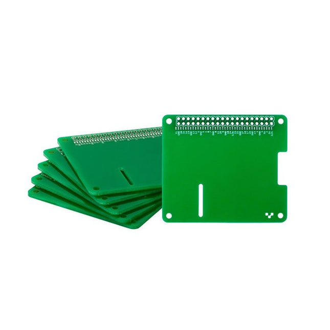
Thanks to its six sturdy slots, Breakout Garden enables the users to simply plug and play with various tiny breakout board.Just insert one or more boards into the slots in the Breakout Garden HAT and you’re ready to go. The mini breakouts feel secure enough in the edge-connector slots and are very unlikely to fall out.There are a number of useful pins along the top of Breakout Garden, which lets you connect other devices and integrate them into your project.You shouldn't be worried if you insert a board the wrong way thanks to provided reverse polarity protection. It doesn't matter which slot you use for each breakout either, because the I²C address of the breakout will be recognised by the software and it'll detect them correctly in case you move them around.Features
Six sturdy edge-connector slots for Pimoroni breakouts
0.1” pitch, 5 pin connectors
Broken-out pins (1 × 10 strip of male header included)
Standoffs (M2.5, 10 mm height) included to hold your Breakout Garden securely
Reverse polarity protection (built into breakouts)
HAT format board
Compatible with Raspberry Pi 3 B+, 3, 2, B+, A+, Zero, and Zero W
It's suggested using the included standoffs to attache Breakout Garden to your Raspberry Pi.SoftwareBreakout Garden doesn't require any software of its own, but each breakout you use will need a Python library. On the Breakout Garden GitHub page you'll find an automatic installer, which will install the appropriate software for a given breakout. There are also some examples that show you what else you can do with Breakout Garden.
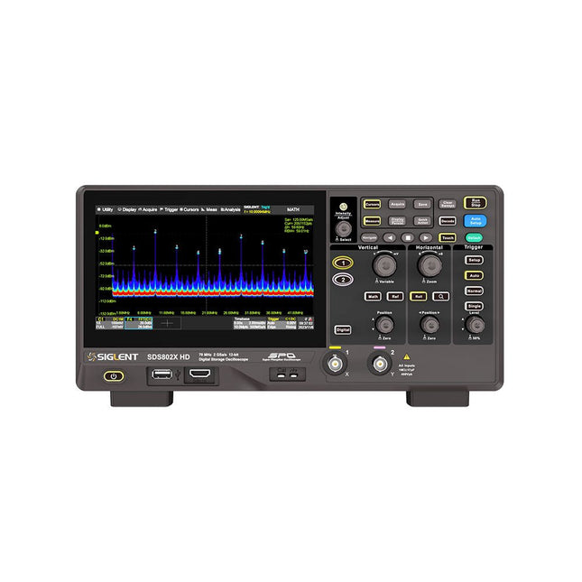
The Siglent SDS822X HD digital storage oscilloscope is based on 2 GSa/s, 12-bit Analog-Digital Converters and front ends with excellent noise floor performance. With a 200 MHz bandwidth, and a maximum record length of 100 Mpts, and the capability to analyze 2 analog channels alongside 16 digital channels, the SDS822X HD is perfectly suited for mixed signal analysis.
Features
12-bit High Resolution
12-bit Analog-Digital Convertors with sample rate up to 2 GSa/s
Front ends with 70 μVrms noise floor @ 200 MHz bandwidth
2/4 analog channels, up to 700 MHz bandwidth
SPO technology
Waveform capture rate up to 120,000 wfm/s (normal mode), and 500,000 wfm/s (sequence mode)
Supports 256-level intensity grading and color temperature display modes.
Up to 50 Mpts record length
Digital trigger system
Intelligent trigger: Edge, Slope, Pulse width, Window, Runt, Interval, Dropout, Pattern, Video (HDTV supported), Qualified, Nth edge, Delay, Setup/Hold time.
Serial bus triggering and decoder, supports protocols I²C, SPI, UART, CAN, LIN.
Segmented acquisition (Sequence) mode, dividing the maximum record length into multiple segments (up to 80,000), according to trigger conditions set by the user, with a very small dead time between segments to capture the qualifying event.
History waveform record (History) function, the maximum recorded waveform length is 80,000 frames.
Automatic measurements on 50+ parameters, supports statistics with histogram, track, trend, Gating measurement, and measurements on Math, History and Ref.
4 Math traces (2 Mpts FFT, addition, subtraction, multiplication, division, integration, differential, square root, etc.), supports formula editor.
Abundant data analysis functions such as Search, Navigate, Counter, Bode plot and Power Analysis
High Speed hardware-based Mask Test function, with Mask Editor tool for creating user-defined masks
16 digital channels (optional)
25 MHz waveform generator (optional)
7" TFT-LCD display with 1024 x 600 resolution; Capacitive touch screen supports multi-touch gestures.
Interfaces include: USB Hosts, USB Device (USBTMC), LAN (VXI-11/Telnet/Socket), Pass/Fail, Trigger Out
Built-in web server supports remote control over the LAN port using a web browser. Supports SCPI remote control commands. Supports external mouse and keyboard. Supports NTP.
Specifications
Analog Channels
2
Bandwidth
200 MHz
Vertical resolution
12-bit
Sample rate (Max.)
One channel mode: 100 Mpts/chTwo channel mode: Mpts/chFour channel mode: 25 Mpts/ch
Memory depth (Max.)
One channel mode: 50 Mpts/chTwo channel mode: 25 Mpts/ch
Waveform capture rate (Max.)
Normal mode: 120,000 wfm/sSequence mode: 500,000 wfm/s
Trigger type
Edge, Slope, Pulse width, Window, Runt, Interval, Dropout, Pattern, Video, Qualified, Nth edge, Delay, Setup/Hold time, Serial
Serial trigger and decode (Standard)
I²C, SPI, UART, CAN, LIN
Measurement
50+ parameters, statistics, histogram, trend, and track supported
Math
4 traces 2 Mpts FFT, Filter, +, -, x, ÷, ∫dt, d/dt, √, Identity, Negation, Absolute, Sign, ex, 10x, ln, lg, Interpolation, MaxHold, MinHold, ERES, Average. Supports formula editor
Data analysis
Search, Navigate, History, Mask Test, Counter, Bode plot, and Power Analysis
Digital channel (optional)
16-channel; maximum sample rate up to 1 GSa/s; record length up to 10 Mpts
USB AWG module (option)
One channel, 25 MHz, sample rate of 125 MHz, wave length of 16 kpts, isolated output
I/O
2x USB 2.0 Host, USB 2.0 Device, 10/100 M LAN, Auxiliary output (TRIG OUT, PASS/FAIL), SBUS (Siglent MSO)
Probe (Standard)
Passive probe PB470 for each channel
Display
7 TFT-LCD with capacitive touch screen (1024x600)
Included
1x Siglent SDS822X Oscilloscope
2x Passive probe (200 MHz) PP520
1x Power cord (EU)
1x USB cable
1x Certificate of calibration
1x Quick start
Downloads
Datasheet
Manual
Programming guide
The Internet of Things is rapidly gaining interest, and that has fueled the development of the Edison. A tiny computer, the size of a postage stamp, with a lot of power and built-in wireless communication capabilities.
In this eBook we will help you get up-to-speed with the Edison, by installing the software both on the Edison as well as on your Windows PC. We will use the Edison Arduino break-out board because it is easy to work with. We will discuss Linux, Arduino C++ and Python, and show examples of how the Edison can interface with other hardware. We will use Wi-Fi and Bluetooth to set up wireless connections, and show you a trick to program sketches over Wi-Fi.
Once you have completed this book your Edison will be up and running with the latest software version, and you will have sufficient knowledge of both hardware and software to start making your own applications. You will even be able to program the Edison over USB and wireless both in Arduino C++ and Python.
This is not a projects eBook, but a toolbox that will allow you to explore the wonderful world of the Intel Edison!
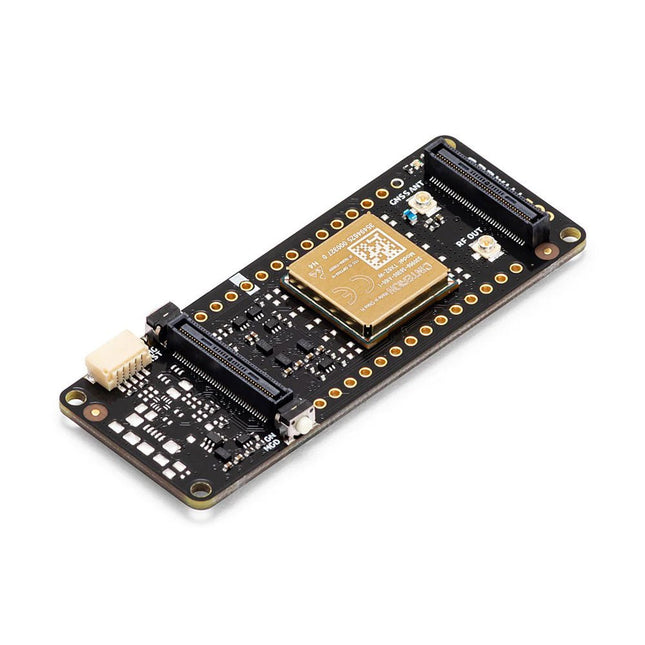
The Arduino Pro Portenta Cat. M1/NB IoT GNSS Shield allows you to enhance the connectivity features of your Portenta H7 applications. The shield leverages a Cinterion TX62 wireless module by Thales, designed for highly efficient, low-power IoT applications to deliver optimized bandwidth and performance.
The Portenta Cat. M1/NB IoT GNSS Shield combines with the strong edge computing power of the Portenta H7 to enable the development of asset tracking and remote monitoring applications in industrial settings, as well as in agriculture, public utilities and smart cities. The shield offers cellular connectivity to both Cat. M1 and NB-IoT networks with the option to use eSIM technology. Easily track your valuables – across the city or worldwide – with your choice of GPS, GLONASS, Galileo or BeiDou.
Features
Change connectivity capabilities without changing the board
Add NB-IoT, CAT. M1 and positioning to any Portenta product
Possibility to create a small multiprotocol router (WiFi - BT + NB-IoT/CAT. M1)
Greatly reduce communication bandwidth requirements in IoT applications
Low-power module
Compatible also with MKR boards
Remote Monitoring
Industrial and agricultural companies can leverage the Portenta Cat. M1/NB IoT GNSS Shield to remotely monitor gas detectors, optical sensors, machinery alarm systems, biological bug traps and more.
Technology providers providing smart city solutions can compound the power and reliability of the Portenta H7 with the Portenta Cat. M1/NB IoT GNSS Shield, to connect data and automate actions for a truly optimized use of resources and enhanced user experience.
Asset Monitoring
Add monitoring capabilities to any asset by combining the performance and edge computing features of the Portenta family boards. The Portenta Cat. M1/NB IoT GNSS Shield is ideal to monitor valuable goods and also for monitoring industrial machinery and equipment.
Specifications
Connectivity
Cinterion TX62 wireless module; NB-IoT - LTE CAT.M1; 3GPP Rel.14 Compliant Protocol LTE Cat. M1/NB1/NB2; UMTS BANDS: 1 / 2 / 3 / 4 / 5 / 8 / 12(17) / 13 / 18 / 19 / 20 / 25 / 26 / 27 / 28 / 66 / 71 / 85; LTE Cat.M1 DL: max. 300 kbps, UL: max. 1.1 Mbps; LTE Cat.NB1 DL: max. 27 kbps, UL: max. 63 kbps; LTE Cat.NB2 DL: max. 124 kbps, UL: max. 158 kbps
Short messaging service (SMS)
Point-to-point mobile terminated (MT) and mobile originated (MO) Text Mode; Protocol Data Unit (PDU) Mode
Localization support
GNSS capability (GPS/BeiDou/Galileo/GLONASS)
Other
Embedded IPv4 and IPv6 TCP/IP stack access; Internet Services: TCP server/client, UDP client, DNS, Ping, HTTP client, FTP client, MQTT client Secure Connection with TLS/DTLS Secure boot
Dimensions
66 x 25.4 mm
Operating temperature
-40° C to +85° C (-104° F to 185°F)
Downloads
Datasheet
Schematics
The Arduino Pro Portenta Vision Shield LoRa brings industry-rated features to your Portenta. This hardware add-on will let you run embedded computer vision applications, connect wirelessly via LoRa to the Arduino Cloud or your own infrastructure, and activate your system upon the detection of sound events.
The shield comes with:
a 320x320 pixels camera sensor: use one of the cores in Portenta to run image recognition algorithms using the OpenMV for Arduino editor
long range 868/915 MHz LoRa wireless connectivity: get your Portenta H7 connected to the Internet of Things with low power consumption
two on-board microphones for directional sound detection: capture and analyse sound in real-time
JTAG connector: perform low-level debugging of your Portenta board or special firmware updates using an external programmer
SD-Card connector: store your captured data in the card, or read configuration files
The Vision Shield LoRa has been designed to work with the Arduino Portenta H7. The Portenta boards feature multicore 32-bit ARM Cortex processors running at hundreds of megahertz, with megabytes of program memory and RAM. Portenta boards come with WiFi and Bluetooth.
Specifications
Camera
Himax HM-01B0 camera module (manufacturer site)
Resolution
320 x 320 active pixel resolution with support for QVGA
Image sensor
High sensitivity 3.6μ BrightSense pixel technology
Microphone
2x MP34DT05 (datasheet)
Connectivity
868/915MHz ABZ-093 LoRa Module with ARM Cortex-M0+ (datasheet)
Dimensions
66 x 25 mm
Weight
8 g
Downloads
Datasheet
Schematics