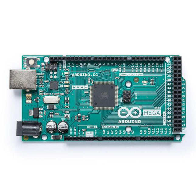
It contains everything needed to support the microcontroller; simply connect it to a computer with a USB cable or power it with an AC-to-DC adapter or battery to get started. The Mega 2560 board is compatible with most shields designed for the Uno and the former boards Duemilanove or Diecimila. Operating Voltage 5 V Input Voltage 7 V - 12 V Digital I/O 54 Analog Input Pins 16 DC Current per I/O Pin 20 mA DC Current for 3.3 V Pin 50 mA Flash Memory 256 KB of which 8 KB used by the bootloader SRAM 8 KB EEPROM 4 KB Clock Speed 16MHz LED_Builtin 13 Length 101.52 mm Width 53.3 mm Weight 37 g For more information, check out the Getting Started Guide from Arduino.
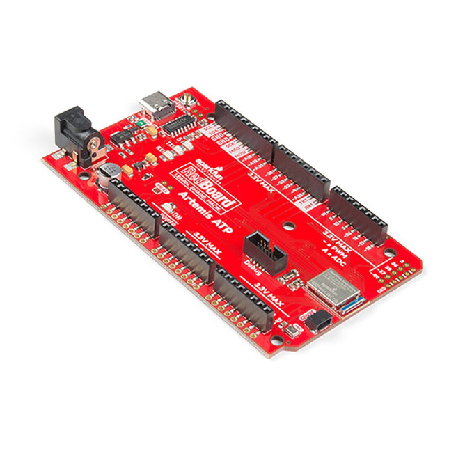
What's with the silkscreen labels? They're all over the place. We decided to label the pins as they are assigned on the Apollo3 IC itself. This makes finding the pin with the function you desire a lot easier. Have a look at the full pin map from the Apollo3 datasheet. If you really need to test out the 4-bit SPI functionality of the Artemis, you're going to need to access pins 4, 22, 23, and 26. Need to try out the differential ADC port 1? Pins 14 and 15. The RedBoard Artemis ATP will allow you to flex the impressive capabilities of the Artemis module.
The RedBoard Artemis ATP has the improved power conditioning and USB to serial that we've refined over the years on our RedBoard line of products. A modern USB-C connector makes programming easy. A Qwiic connector makes I²C easy. The ATP is fully compatible with SparkFun's Arduino core and can be programmed easily under the Arduino IDE. We've exposed the JTAG connector for more advanced users who prefer to use the power and speed of professional tools. If you need a lot of a GPIO with a simple program, ready to go to the market module, the ATP is the fix you need. We've added a digital MEMS microphone for folks wanting to experiment with always-on voice commands with TensorFlow and machine learning. We've even added a convenient jumper to measure current consumption for low power testing.
With 1 MB flash and 384k RAM, you'll have plenty of room for your sketches. The Artemis module runs at 48 MHz with a 96 MHz turbo mode available and with Bluetooth to boot!
Features
Arduino Mega Footprint
1M Flash / 384k RAM
48MHz / 96MHz turbo available
6uA/MHz (operates less than 5mW at full operation)
48 GPIO - all interrupt capable
31 PWM channels
Built-in BLE radio
10 ADC channels with 14-bit precision with up to 2.67 million samples per second effective continuous, multi-slot sampling rate
2 channel differential ADC
2 UARTs
6 I²C buses
6 SPI buses
2/4/8-bit SPI bus
PDM interface
I²S Interface
Secure 'Smart Card' interface
Qwiic Connector
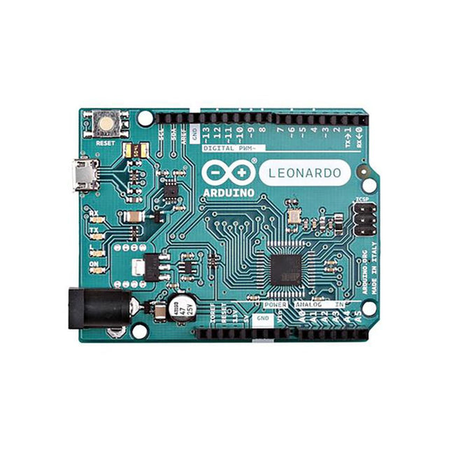
The Leonardo differs from all preceding boards in that the ATmega32u4 has built-in USB communication, eliminating the need for a secondary processor. This allows the Leonardo to appear to a connected computer as a mouse and keyboard, in addition to a virtual (CDC) serial / COM port.
Specifications
Microcontroller
ATMega4809
Operating Voltage
5 V
Input Voltage
7 V - 12 V
Analog Input Pins
12
PWM Pins
7
DC I/O Pin
20
DC Current per I/O Pin
20 mA
DC Current for 3.3 V Pin
50 mA
Flash Memory
32 KB of which 4 KB used by the bootloader
SRAM
2.5 KB
EEPROM
1 KB
Clock Speed
16 MHz
Length
68.6 mm
Width
53.3 mm
Weight
20 g
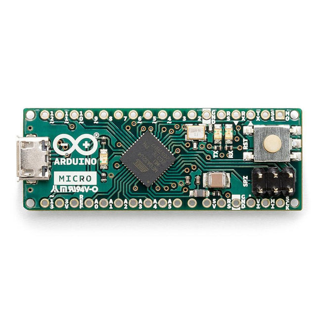
The Arduino Micro contains everything needed to support the microcontroller; simply connect it to a computer with a micro USB cable to get started. It has a form factor that enables it to be easily placed on a breadboard.
The Micro board is similar to the Arduino Leonardo in that the ATmega32U4 has built-in USB communication, eliminating the need for a secondary processor. This allows the Micro to appear to a connected computer as a mouse and keyboard, in addition to a virtual (CDC) serial / COM port.
Specifications
Microcontroller
ATmega32U4
Operating Voltage
5 V
Input Voltage
7 V - 12 V
Analog Input Pins
12
PWM Pins
7
DC I/O Pin
20
DC Current per I/O Pin
20 mA
DC Current for 3.3 V Pin
50 mA
Flash Memory
32 KB of which 4 KB used by the bootloader
SRAM
2.5 KB
EEPROM
1 KB
Clock Speed
16 MHz
LED_Builtin
13
Length
45 mm
Width
18 mm
Weight
13 g
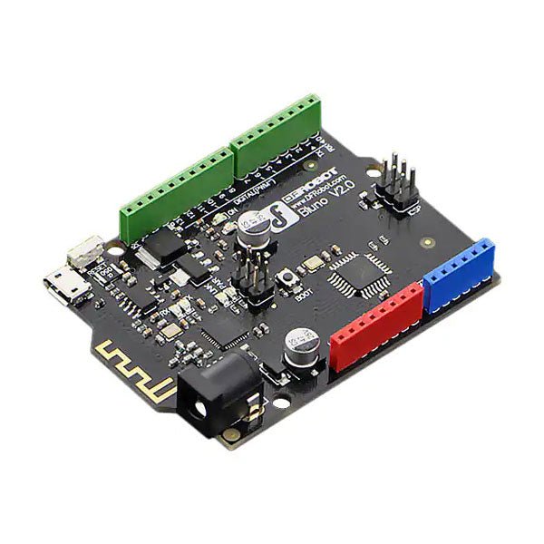
Bluno is the first of its kind in integrating Bluetooth 4.0 (BLE) module into Arduino Uno, making it an ideal prototyping platform for both software and hardware developers to go BLE. You will be able to develop your own smart bracelet, smart pedometer, and more. Through the low-power Bluetooth 4.0 technology, real-time low energy communication can be made really easy.
Bluno integrates a TI CC2540 BT 4.0 chip with the Arduino UNno. It allows wireless programming via BLE, supports Bluetooth HID, AT command to config BLE and you can upgrade BLE firmware easily. Bluno is also compatible with all 'Arduino Uno' pins which means any project made with Uno can directly go wireless!
Specifications
On-board BLE chip: TI CC2540
Wireless Programming via BLE
Support Bluetooth HID
Support AT command to config the BLE
Transparent communication through Serial
Upgrade BLE firmware easily
DC Supply: USB Powered or External 7~12 V DC
Microcontroller: Atmega328
Bootloader: Arduino Uno ( disconnect any BLE device before uploading a new sketch )
Compatible with the Arduino Uno pin mapping
Size: 60 x 53 mm(2.36 x 2.08')
Weight: 30 g
The board's main processor is a low-power Arm® Cortex®-M0 32-bit SAMD21. The WiFi and Bluetooth® connectivity is performed with a module from u-blox, the NINA-W10, a low-power chipset operating in the 2.4GHz range. On top of that, secure communication is ensured through the Microchip® ECC608 crypto chip. Besides that, you can find a 6 axis IMU, which makes this board perfect for simple vibration alarm systems, pedometers, the relative positioning of robots, etc. WiFi and Arduino IoT Cloud You can get your board to connect to any kind of existing WiFi network, or use it to create your own Arduino Access Point. The specific set of examples we provide for the Nano 33 IoT can be consulted at the WiFiNINA library reference page. It is also possible to connect your board to different Cloud services, Arduino's own among others. Here are some examples of how to get the Arduino boards to connect to:
Arduino's own IoT Cloud: Arduino's IoT Cloud is a simple and fast way to ensure secure communication for all of your connected Things. Check it out here.
Blynk: a simple project from our community connecting to Blynk to operate your board from a phone with little code.
IFTTT: see an in-depth case of building a smart plug connected to IFTTT.
AWS IoT Core: we made this example on how to connect to Amazon Web Services.
Azure: visit this GitHub repository explaining how to connect a temperature sensor to Azure's Cloud.
Firebase: you want to connect to Google's Firebase, this Arduino library will show you how. Microcontroller SAMD21 Cortex®-M0+ 32bit low power ARM MCU Radio Module u-blox NINA-W102 Secure Element ATECC608A Operating Voltage 3.3 V Input Voltage 21 V Digital I/O Pins 14 PWM Pins 11 DC Current per I/O Pin 7 mA Analog Input Pins 8 Analog Output Pins 1 External Interrupts all digital pins UART 1 SPI 1 I2C 1 Flash Memory 256 KB SRAM 32 KB EEPROM none Clock Speed 48 MHz LED_Builtin 13 USB Native in the SAMD21 Processor IMU LSM6DS3 Length 45 mm Width 18 mm Weight 5 g
The board's main processor is a low-power ARM Cortex-M0 32-bit SAMD21, like in the other boards within the Arduino MKR family. The WiFi and Bluetooth connectivity is performed with a module from u-blox, the NINA-W10, a low-power chipset operating in the 2.4 GHz range. On top of that, secure communication is ensured through the Microchip ECC508 crypto chip. Besides that, you can find a battery charger, and an RGB LED on-board.
Official Arduino WiFi Library
You can get your board to connect to any kind of existing WiFi network, or use it to create your own Arduino Access Point. The specific set of examples we provide for the MKR WiFi 1010 can be consulted at the WiFiNINA library reference page.
Compatible with other Cloud Services
It is also possible to connect your board to different Cloud services, Arduino's own among others. Here are some examples of how to get the MKR WiFi 1010 to connect to:
Blynk: a simple project from the Arduino community connecting to Blynk to operate your board from a phone with little code
IFTTT: in-depth case of building a smart plug connected to IFTTT
AWS IoT Core: Arduino made this example on how to connect to Amazon Web Services
Azure: visit this GitHub repository explaining how to connect a temperature sensor to Azure's Cloud
Firebase: you want to connect to Google's Firebase, this Arduino library will show you how
Specifications
Microcontroller
SAMD21 Cortex-M0+ 32bit low power ARM MCU
Radio Module
u-blox NINA-W102
Power Supply
5 V
Secure Element
ATECC508
Supported Battery
Li-Po Single Cell, 3.7 V, 1024 mAh Minimum
Operating Voltage
3.3 V
Digital I/O Pins
8
PWM Pins
13
UART
1
SPI
1
I2C
1
Analog Input Pins
7
Analog Output Pins
1
External Interrupts
10
Flash Memory
256 KB
SRAM
32 KB
EEPROM
no
Clock Speed
32.768 kHz, 48 MHz
LED_Builtin
6
USB
Full-Speed USB Device and embedded Host
Length
61.5 mm
Width
25 mm
Weight
32 g
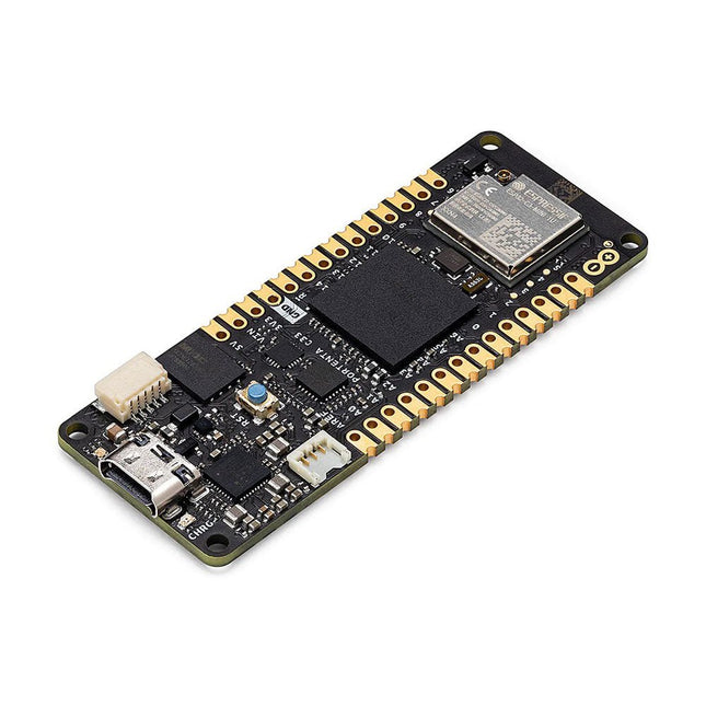
The Arduino Nano 33 BLE Sense Rev2 with headers is Arduino’s 3.3 V AI enabled board in the smallest available form factor with a set of sensors that will allow you without any external hardware to start programming your next project, right away.
With the Arduino Nano 33 BLE Sense Rev2, you can:
Build wearable devices that using AI can recognize movements.
Build a room temperature monitoring device that can suggest or modify changes in the thermostat.
Build a gesture or voice recognition device using the microphone or the gesture sensor together with the AI capabilities of the board.
Differences between Rev1 and Rev2
Replacement of IMU from LSM9DS1 (9 axis) for a combination of two IMUs (BMI270 – 6 axis IMU and BMM150 – 3 axis IMU)
Replacement of temperature and humidity sensor from HTS221 for HS3003
Replacement of microphone from MP34DT05 to MP34DT06JTR
Replacement of power supply MPM3610 for MP2322
Addition of VUSB soldering jumper on the top side of the board
New test point for USB, SWDIO and SWCLK
Specifications
Microcontroller
nRF52840 (datasheet)
Operating Voltage
3.3 V
Input Voltage (limit)
21 V
DC Current per I/O Pin
15 mA
Clock Speed
64 MHz
CPU Flash Memory
1 MB (nRF52840)
SRAM
256 KB (nRF52840)
EEPROM
None
Digital Input / Output Pins
14
PWM Pins
All digital pins
UART
1
SPI
1
I²C
1
Analog Input Pins
8 (ADC 12 bit 200 k samples)
Analog Output Pins
Only through PWM (no DAC)
External Interrupts
All digital pins
LED_BUILTIN
13
USB
Native in the nRF52840 Processor
IMU
BMI270 (datasheet) and BMM150 (datasheet)
Microphone
MP34DT06JTR (datasheet)
Gesture, light, proximity, color
APDS9960 (datasheet)
Barometric pressure
LPS22HB (datasheet)
Temperature, humidity
HS3003 (datasheet)
Downloads
Datasheet
Schematics
The ATmega328 Uno Development Board (Arduino Uno compatible) is a microcontroller board based on the ATmega328.
It has 14 digital input/output pins (of which 6 can be used as PWM outputs), 6 analogue inputs, a 16 MHz ceramic resonator, a USB connection, a power jack, an ICSP header and a reset button.
It contains everything needed to support the microcontroller; connect it to a computer with a USB cable or power it with a AC-to-DC adapter or battery to get started.
Specifications
Microcontroller
ATmega328
Operating voltage
5 V DC
Input voltage (recommended)
7-12 V DC
Input voltage (limits)
6-20 V DC
Digital I/O pins
14 (of which 6 provide PWM output)
Analogue input pins
6
SRAM
2 kB (ATmega328)
EEPROM
1 kB (ATmega328)
Flash memory
32 kB (ATmega328) of which 0.5 kB used by bootloader
Clock speed
16 MHz
Downloads
Manual
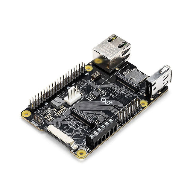
The Portenta C33 is a powerful System-on-Module designed for low-cost Internet of Things (IoT) applications. Based on the R7FA6M5BH2CBG microcontroller from Renesas, this board shares the same form factor as the Portenta H7 and it is backward compatible with it, making it fully compatible with all Portenta family shields and carriers through its high-density connectors.
As a low-cost device, the Portenta C33 is an excellent choice for developers looking to create IoT devices and applications on a budget. Whether you're building a smart home device or a connected industrial sensor, the Portenta C33 provides the processing power and connectivity options you need to get the job done.
Quickly deploying AI-powered projects becomes quick and easy with Portenta C33, by leveraging a vast array of ready-to-use software libraries and Arduino sketches available, as well as widgets that display data in real time on Arduino IoT Cloud-based dashboards.
Features
Ideal for low-cost IoT applications with Wi-Fi/Bluetooth LE connectivity
Supports MicroPython and other high-level programming languages
Offers industrial-grade security at the hardware level and secure OTA firmware updates
Leverages ready-to-use software libraries and Arduino sketches
Perfect to monitor and display real-time data on Arduino IoT Cloud widget-based dashboards
Compatible with Arduino Portenta and MKR families
Features castellated pins for automatic assembly lines
Cost Effective Performance
Reliable, secure and with computational power worthy of its range, Portenta C33 was designed to provide big and small companies in every field with the opportunity to access IoT and benefit from higher efficiency levels and automation.
Applications
Portenta C33 brings more applications than ever within users’ reach, from enabling quick plug-and-play prototyping to providing a cost-effective solution for industrial-scale projects.
Industrial IoT gateway
Machine monitoring to track OEE/OPE
Inline quality control and assurance
Energy consumption monitoring
Appliances control system
Ready-to-use IoT prototyping solution
Specifications
Microcontroller
Renesas R7FA6M5BH2CBG ARM Cortex-M33:
ARM Cortex-M33 core up to 200 MHz
512 kB onboard SRAM
2 MB onboard Flash
Arm TrustZone
Secure Crypto Engine 9
External Memories
16 MB QSPI Flash
USB-C
USB-C High Speed
Connectivity
100 MB Ethernet interface (PHY)
Wi-Fi
Bluetooth Low Energy
Interfaces
CAN
SD Card
ADC
GPIO
SPI
I²S
I²C
JTAG/SWD
Security
NXP SE050C2 Secure Element
Operating Temperatures
-40 to +85°C (-40 to 185°F)
Dimensions
66,04 x 25,40 mm
Downloads
Datasheet
Schematics
Portenta X8 is a powerful, industrial-grade SOM with Linux OS preloaded onboard, capable of running device-independent software thanks to its modular container architecture. Take advantage of onboard Wi-Fi/Bluetooth Low Energy connectivity to securely perform OS/application OTA updates. It’s basically two industrial products in one, with the power of no less than 9 cores. Leverage the Arduino environment to carry out real-time tasks while Linux takes care of high-performance processing. Portenta X8 features an NXP i.MX 8M Mini Cortex-A53 quad-core, up to 1.8 GHz per core + 1x Cortex-M4 up to 400 MHz, plus the STMicroelectronics STM32H747 dual-core Cortex-M7 up to 480 Mhz +M4 32-bit ARM MCU up to 240 Mhz. Features Two industrial products in one, combining Arduino’s availability of libraries/skills with container-based Linux distribution Outstanding computational density – a total of 9 cores within a compact form factor Multi-processor architecture allowing power-optimized processing Leverage popular programming languages like Python, Java and Ruby among others Real-time I/O and fieldbus/control on a dedicated core Deploy powerful AI algorithms and machine learning on the edge Secure OS/applications updates over-the-air Industrial-grade security at the hardware level, thanks to its crypto chip on dedicated bus Leverage the Arduino ecosystem to expand Portenta capabilities Implement multi-protocol routing with a single module Compatible with other Arduino Portenta products Industrial-Grade Security Portenta X8 has been designed with industrial-grade security in mind. PSA Certified and includes the NXP SE050C2 hardware security element to provide key generation, accelerated crypto operations and secure storage. Awarded Arm SystemReady certification and integrated Parsec services, making it one of the market’s first Cassini Products available to developers. Portenta X8 includes the customizable open-source Linux microPlatform OS, built using best industry practices for end-to-end security, incremental OTA updates and fleet management. Utilizing the cloud-based DevOps platform from Foundries.io to reinvent the way embedded Linux solutions are built, tested, deployed and maintained, the Portenta X8 benefits from Foundries.io continuous update service for cybersecurity. This service guarantees an updated image that contains all vulnerability patches; whilst the approach to containers decouples the operating system from the application, to seamlessly keep the whole system updated. Applications Portenta X8 enables IT professionals, system integrators and consulting firms to build and boost a wide variety of solutions for industrial contexts, and also lends itself to building automation and smart agriculture applications. Connected edge computer for manufacturing Autonomous Guided Vehicles (AGV) Interactive full-HD secure kiosks and digital signage Office & home control systems Navigation and control for smart agriculture Behavioral analytics for offices and factories Downloads Datasheet Schematics
Portenta H7 Lite allows you to build your next smart project.
Ever wanted an automated house? Or a smart garden? Well, now it’s easy with the Arduino IoT Cloud compatible boards. It means: you can connect devices, visualize data, control and share your projects from anywhere in the world.
The Arduino Pro Portenta H7 Lite is very similar to the Portenta H7, that simultaneously can run high level code along with real time tasks thanks to its two processors. It is, for example, possible to execute Arduino compiled code along with MicroPython one and have both cores to communicate with one another. However, the H7 Lite is a low-cost board with H7 functionalities that can be configured to specific use cases.
Features
Dual Core – Two best-in-class processors in one, running parallel tasks
AI on the edge – So powerful it can run AI state machines
Customization – The board is highly customizable in volumes
High-level programming language support (Micropython)
The Portenta H7 Lite offers twofold functionality: it can run either like any other embedded microcontroller board, or as the main processor of an embedded computer.
For example, use the Portenta Vision Shield to transform your H7 Lite into an industrial camera capable of performing real-time machine learning algorithms on live video feeds. As the H7 Lite can easily run processes created with TensorFlow Lite, you could have one of the cores computing a computer vision algorithm on the fly, while the other carries out low-level operations like controlling a motor or acting as a user interface.
Solutions
High-end industrial machinery
Laboratory equipment
Computer vision
PLCs
Robotics controllers
Mission-critical devices
High-speed booting computation (ms)
Two Parallel Cores
The Portenta H7 Lite’s main processor is the STM32H747 dual core including a Cortex-M7 running at 480 MHz and a Cortex-M4 running at 240 MHz. The two cores communicate via a Remote Procedure Call mechanism that allows calling functions on the other processor seamlessly. Both processors share all the in-chip peripherals and can run:
Arduino sketches on top of the ARM Mbed OS
Native Mbed applications
MicroPython / JavaScript via an interpreter
TensorFlow Lite
A New Standard for Pinouts
The Portenta family adds two 80-pin high-density connectors at the bottom of the board. This ensures scalability for a wide range of applications: simply upgrade your Portenta board to the one suiting your needs.
USB-C Multipurpose Connector
The board’s programming connector is a USB-C port that can also be used to power the board, as a USB Hub, or to deliver power to OTG connected devices.
Arduino IoT Cloud
Use your Portenta board on Arduino’s IoT Cloud, a simple and fast way to ensure secure communication for all of your connected Things.
Specifications
Microcontroller
STM32H747XI Dual Cortex-M7+M4 32-bit low power ARM MCU (datasheet)
Secure element (default)
Microchip ATECC608
Board power supply (USB/VIN)
5 V
Supported battery
Li-Po Single Cell, 3.7 V, 700 mAh Minimum (integrated charger)
Circuit operating voltage
3.3 V
Current consumption
2.95 μA in Standby mode (Backup SRAM OFF, RTC/LSE ON)
Timers
22x timers and watchdogs
UART
4x ports (2 with flow control)
Ethernet PHY
10 / 100 Mbps (through expansion port only)
SD card
Interface for SD card connector (through expansion port only)
Operational temperature
-40 °C to +85 °C
MKR headers
Use any of the existing industrial MKR shields on it
High-density connectors
Two 80-pin connectors will expose all of the board's peripherals to other devices
Camera interface
8-bit, up to 80 MHz
ADC
3x ADCs with 16-bit max. resolution (up to 36 channels, up to 3.6 MSPS)
DAC
2x 12-bit DAC (1 MHz)
USB-C
Host / Device, High / Full Speed, Power delivery
Downloads
Datasheet
Schematics
The Arduino Pro Portenta Max Carrier transforms Portenta modules into single-board computers or reference designs that enable edge AI for high-performance industrial, building automation and robotics applications. Thanks to dedicated high-density connectors, it can be paired with Portenta X8 or H7, allowing you to easily prototype and deploy your industrial projects. This Arduino Pro carrier further augments Portenta connectivity options with Fieldbus, LoRa, Cat-M1 and NB-IoT.
Among the many available plug-and-play connectors there are Ethernet, USB-A, audio jacks, microSD, mini-PCIe, FD-CAN and Serial RS232/422/485.
Max Carrier can be powered via external supply (6-36 V) or battery via the onboard 18650 Li-ion battery connector with 3.7 V battery charger.
Features
Easily prototype industrial applications and minimize time to market
A powerful carrier exposing Portenta peripherals (e.g. CAN, RS232/422/485, USB, mPCIe)
Multiple connectivity options (Ethernet, LoRa, CAT-M1, NB-IoT)
MicroSD for data logging operations
Integrated audio jacks (line-in, line-out, mic-in)
Standalone when battery powered
Onboard JTAG debugger via micro-USB (with Portenta H7 only)
Specifications
Connectors
High-Density connectors compatible with Portenta products2x USB-A female connectors1x Gigabit Ethernet connector (RJ45)1x FD-Can on RJ111x mPCIe1x Serial RS232/422/485 on RJ12
Audio
3x audio jacks: stereo line-in/line-out, mic-inSpeaker connector
Memory
Micro SD
Wireless modules
Murata CMWX1ZZABZ-078 LoRaSARA-R412M-02B (Cat.M1/NB-IoT)
Operating temperatures
-40 °C to +85 °C (-40° F to 185 °F)
Debugging
Onboard JLink OB / Blackmagic probe
Power/battery
Power Jack for external supply (6-36 V)On-board 18650 Li-ion battery connector with battery charger (3.7 V)
Dimensions
101.6 x 101.6 mm (4.0 x 4.0')
Downloads
Datasheet
Schematics
The Arduino MKR Zero is a development board for music makers! With an SD card holder and dedicated SPI interfaces (SPI1), you are able to play music files without extra hardware. The MKR Zero brings you the power of a Zero in the smaller format established by the MKR form factor. The MKR Zero board acts as a great educational tool for learning about 32-bit application development. It has an on-board SD connector with dedicated SPI interfaces (SPI1) that allows you to play with MUSIC files with no extra hardware! The board is powered by Atmel’s SAMD21 MCU, which features a 32-bit ARM Cortex M0+ core. The board contains everything needed to support the microcontroller; simply connect it to a computer with a micro-USB cable or power it by a LiPo battery. The battery voltage can also be monitored since a connection between the battery and the analog converter of the board exists. Specifications Microcontroller SAMD21 ARM Cortex-M0+ 32-bit low power Board power supply (USB/VIN) 5 V Supported battery Li-Po single cell, 3.7 V, 700 mAh minimum DC current for 3.3 V pin 600 mA DC current for 5 V pin 600 mA Circuit operating voltage 3.3 V Digital I/O pins 22 PWM pins 12 (0, 1, 2, 3, 4, 5, 6, 7, 8, 10, A3 - or 18 -, A4 -or 19) UART 1 SPI 1 I²C 1 Analog input pins 7 (ADC 8/10/12 bit) Analog output pins 1 (DAC 10 bit) External interrupts 10 (0, 1, 4, 5, 6, 7, 8, A1 -or 16-, A2 - or 17) DC current per I/O pin 7 mA Flash memory 256 KB Flash memory for bootloader 8 KB SRAM 32 KB EEPROM No Clock speed 32.768 kHz (RTC), 48 MHz LED_BUILTIN 32 Downloads Datasheet Eagle Files Schematics Fritzing Pinout
Arduino MKR NB 1500 allows you to build your next smart project.
Ever wanted an automated house? Or a smart garden? Well, now it’s easy with the Arduino IoT Cloud compatible boards. It means: you can connect devices, visualize data, control and share your projects from anywhere in the world. Whether you’re a beginner or a pro, we have a wide range of plans to make sure you get the features you need.
Add Narrowband communication to your project with the MKR NB 1500. It's the perfect choice for devices in remote locations without an Internet connection, or in situations in which power isn't available like on-field deployments, remote metering systems, solar-powered devices, or other extreme scenarios.
The board's main processor is a low power ARM Cortex-M0 32-bit SAMD21, like in the other boards within the Arduino MKR family. The Narrowband connectivity is performed with a module from u-blox, the SARA-R410M-02B, a low power chipset operating in the de different bands of the IoT LTE cellular range. On top of those, secure communication is ensured through the Microchip ECC508 crypto chip. Besides that, the pcb includes a battery charger, and a connector for an external antenna.
This board is designed for global use, providing connectivity on LTE's Cat M1/NB1 bands 1, 2, 3, 4, 5, 8, 12, 13, 18, 19, 20, 25, 26, 28. Operators offering service in that part of the spectrum include: Vodafone, AT&T, T-Mobile USA, Telstra, and Verizon, among others.
Specifications
The Arduino MKR NB 1500 is based on the SAMD21 microcontroller.
Microcontroller
SAMD21 Cortex-M0+ 32-bit low power ARM MCU (datasheet)
Radio module
u-blox SARA-R410M-02B (datasheet summary)
Secure element
ATECC508 (datasheet)
Board power supply (USB/VIN)
5 V
Supported battery
Li-Po Single Cell, 3.7 V, 1500 mAh Minimum
Circuit operating voltage
3.3 V
Digital I/O pins
8
PWM pins
13 (0 .. 8, 10, 12, 18 / A3, 19 / A4)
UART
1
SPI
1
I²C
1
Analog input pins
7 (ADC 8/10/12 bit)
Analog output pins
1 (DAC 10 bit)
External interrupts
8 (0, 1, 4, 5, 6, 7, 8, 16 / A1, 17 / A2)
DC current per I/O pin
7 mA
Flash memory
256 KB (internal)
SRAM
32 KB
EEPROM
No
Clock speed
32.768 kHz (RTC), 48 MHz
LED_BUILTIN
6
USB
Full-speed USB device and embedded host
Antenna gain
2 dB
Carrier frequency
LTE bands 1, 2, 3, 4, 5, 8, 12, 13, 18, 19, 20, 25, 26, 28
Power class (radio)
LTE Cat M1 / NB1: Class 3 (23 dBm)
Data rate (LTE M1 halp-duplex)
UL 375 kbps / DL 300 kbps
Data rate (LTE NB1 full-duplex)
UL 62.5 kbps / DL 27.2 kbps
Working region
Multiregion
Device location
GNSS via modem
Power consumption (LTE M1)
min 100 mA / max 190 mA
Power consumption (LTE NB1)
min 60 mA / max 140 mA
SIM card
MicroSIM (not included with the board)
Dimensions
67.6 x 25 mm
Weight
32 g
Downloads
Eagle Files
Schematics
Pinout
Portenta HAT Carrier is a reliable and robust carrier that transforms Portenta X8 into an industrial single board computer compatible with Raspberry Pi HATs and cameras. It is ideal for multiple industrial applications such as building automation and machine monitoring.
Compatible also with Portenta H7 and Portenta C33, Portenta HAT Carrier provides easy access to multiple peripherals – including CAN, Ethernet, microSD and USB – and further extends any Portenta application.
It is great for prototyping and ready for scaling up, it extends the features found on a typical Raspberry Pi Model B. Debug quickly with dedicated JTAG pins and keeps heat manageable under intense workloads with a PWM fan connector. Control actuators or read analog sensors via the additional 16x analog I/Os. Add industrial machine vision solutions to any project by leveraging the onboard camera connector.
Features
Add Raspberry Pi HATs to your Portenta projects
Quickly access CAN, USB, and Ethernet peripherals
Leverage onboard MicroSD card to log data
Enjoy simple debugging through the onboard JTAG pins
Easily control actuators and read sensors via 16x analog I/Os
Leveraging the onboard camera connector for machine vision
Portenta takes you from prototype to high-performance
Portenta HAT Carrier offers you a frictionless Linux prototyping experience and unlocks the ability for integrated real-time MCU solutions. Portenta HAT Carrier extends Portenta SOMs for faster, easier and more efficient testing for your ideas while also ensuring the capabilities and industrial-grade performances the Portenta range is known for.
Extend the Raspberry Pi ecosystem for commercial applications
Combine the ease of use, accessibility and incredible support from both the Arduino and Raspberry Pi communities for your next project with the carrier designed to combine and extend MPU and MCU applications for the development of advanced commercial solutions.
Specifications
Connectors
High-density connectors compatible with Portenta products
1x USB-A female connector
1x Gigabit Ethernet connector (RJ45)
1x CAN FD with onboard transceiver
1x MIPI Camera connector
1x MicroSD card slot
1x PWM fan connector
40-pin header connector allowing compatibility with Raspberry Pi HATs
16-pin analog header connectors, including:
8x analog inputs
1x GPIO
1xUART without flow control
2x PWM pins
1x LICELL pin for Portenta's RTC power
Interfaces
CAN FD
UART
SAI
ANALOG
GPIO
SPI
I²C
I²S
PWM
Debugging
Onboard 10x pin 1.27 mm JTAG connector
Power
From onboard screw terminal block allowing:
7-32 V power supply, powering both the carrier and the connected Portenta
5 V power supply
From USB-C on Portenta
From 5 V on 40-pin header connector
Dimensions
85 x 56 mm
Downloads
Datasheet
Schematics
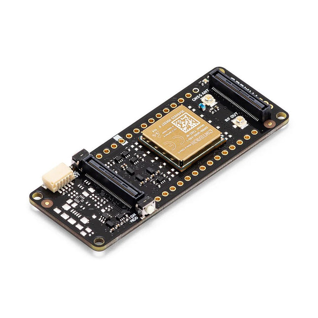
The Arduino Pro Portenta Cat. M1/NB IoT GNSS Shield allows you to enhance the connectivity features of your Portenta H7 applications. The shield leverages a Cinterion TX62 wireless module by Thales, designed for highly efficient, low-power IoT applications to deliver optimized bandwidth and performance.
The Portenta Cat. M1/NB IoT GNSS Shield combines with the strong edge computing power of the Portenta H7 to enable the development of asset tracking and remote monitoring applications in industrial settings, as well as in agriculture, public utilities and smart cities. The shield offers cellular connectivity to both Cat. M1 and NB-IoT networks with the option to use eSIM technology. Easily track your valuables – across the city or worldwide – with your choice of GPS, GLONASS, Galileo or BeiDou.
Features
Change connectivity capabilities without changing the board
Add NB-IoT, CAT. M1 and positioning to any Portenta product
Possibility to create a small multiprotocol router (WiFi - BT + NB-IoT/CAT. M1)
Greatly reduce communication bandwidth requirements in IoT applications
Low-power module
Compatible also with MKR boards
Remote Monitoring
Industrial and agricultural companies can leverage the Portenta Cat. M1/NB IoT GNSS Shield to remotely monitor gas detectors, optical sensors, machinery alarm systems, biological bug traps and more.
Technology providers providing smart city solutions can compound the power and reliability of the Portenta H7 with the Portenta Cat. M1/NB IoT GNSS Shield, to connect data and automate actions for a truly optimized use of resources and enhanced user experience.
Asset Monitoring
Add monitoring capabilities to any asset by combining the performance and edge computing features of the Portenta family boards. The Portenta Cat. M1/NB IoT GNSS Shield is ideal to monitor valuable goods and also for monitoring industrial machinery and equipment.
Specifications
Connectivity
Cinterion TX62 wireless module; NB-IoT - LTE CAT.M1; 3GPP Rel.14 Compliant Protocol LTE Cat. M1/NB1/NB2; UMTS BANDS: 1 / 2 / 3 / 4 / 5 / 8 / 12(17) / 13 / 18 / 19 / 20 / 25 / 26 / 27 / 28 / 66 / 71 / 85; LTE Cat.M1 DL: max. 300 kbps, UL: max. 1.1 Mbps; LTE Cat.NB1 DL: max. 27 kbps, UL: max. 63 kbps; LTE Cat.NB2 DL: max. 124 kbps, UL: max. 158 kbps
Short messaging service (SMS)
Point-to-point mobile terminated (MT) and mobile originated (MO) Text Mode; Protocol Data Unit (PDU) Mode
Localization support
GNSS capability (GPS/BeiDou/Galileo/GLONASS)
Other
Embedded IPv4 and IPv6 TCP/IP stack access; Internet Services: TCP server/client, UDP client, DNS, Ping, HTTP client, FTP client, MQTT client Secure Connection with TLS/DTLS Secure boot
Dimensions
66 x 25.4 mm
Operating temperature
-40° C to +85° C (-104° F to 185°F)
Downloads
Datasheet
Schematics