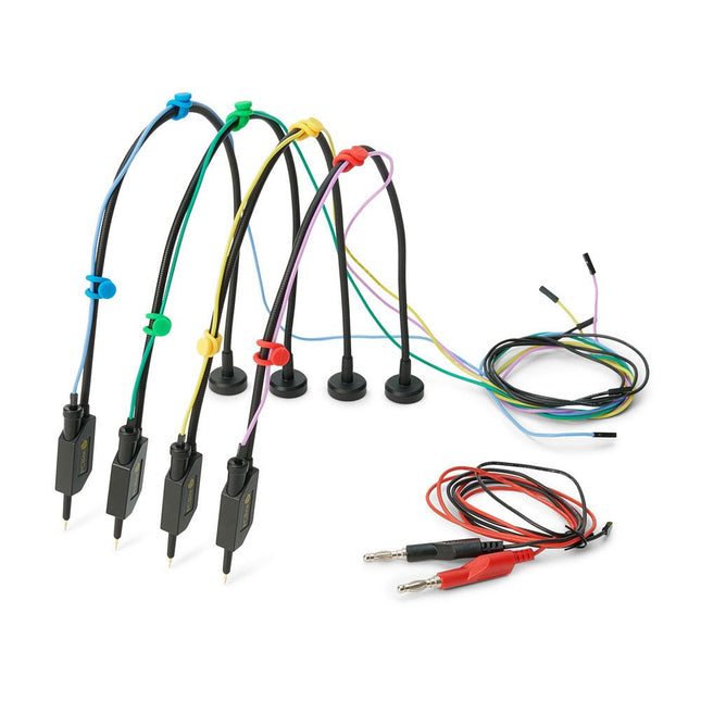
The SQ series of handsfree PCBite probes from Sensepeek are insulated, come with included color-coded cable holders and have a lower point of gravity making them even more stable compared with the original SP series of probes. All the loved features of handsfree measurement, exchangeable fine pitch spring tipped test needle and the minimalistic design is maintained to make traditional sized and handheld probes obsolete. Features All handsfree probes from Sensepeek makes instant measurements or long triggering sessions a breeze. No more soldering wires to connect your probe or complicated tools to setup, just positioning the probe needle on any test point or component in the signal path and release. Saves time and frustration during development, verification and repairs. The minimalist design and the spring-loaded test needle makes it possible to simultaneously measure on fine pitch components and nearby signals. Both length and weight of the SQ probes are perfectly balanced to be used with PCBite PCB holders and base plate which is a must for handsfree function. The probe holder comes with a powerful magnet in the base, as for all PCBite probes and holders which makes the probe easy to place and reposition. The SQ series of probes can be used handheld without the probe holder as they have an insulated grip but their full potential is used when measuring handsfree. Included 4x SQ10 probes and pin tipped test needles (black) 2x Banana to dupont test wires (red/black) 5x Dupont to dupont test wires 1x Set of cable holders (4 colors) 4x Extra test needles Downloads User guide
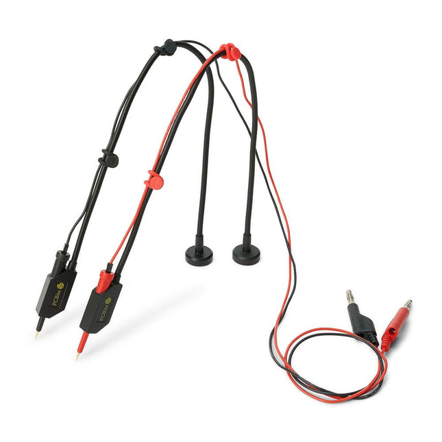
The SQ series of handsfree PCBite probes from Sensepeek are insulated, come with included color-coded cable holders and have a lower point of gravity making them even more stable compared with the original SP series of probes. All the loved features of handsfree measurement, exchangeable fine pitch spring tipped test needle and the minimalistic design is maintained to make traditional sized and handheld probes obsolete. Features All handsfree probes from Sensepeek makes instant measurements or long triggering sessions a breeze. No more soldering wires to connect your probe or complicated tools to setup, just positioning the probe needle on any test point or component in the signal path and release. Saves time and frustration during development, verification and repairs. The minimalist design and the spring-loaded test needle makes it possible to simultaneously measure on fine pitch components and nearby signals. Both length and weight of the SQ probes are perfectly balanced to be used with PCBite PCB holders and base plate which is a must for handsfree function. The probe holder comes with a powerful magnet in the base, as for all PCBite probes and holders which makes the probe easy to place and reposition. The SQ series of probes can be used handheld without the probe holder as they have an insulated grip but their full potential is used when measuring handsfree. Included 2x SQ10 probes and pin tipped test needles (red/black) 2x Banana to dupont test wires (red/black) 1x Set of cable holders (red/black) 2x Extra test needles Downloads User guide
The SQ series of handsfree probes from Sensepeek have a lower point of gravity making them even more stable compared with the original SP series of handsfree probes. All probes in the SQ series are also insulated and can be used handheld as any traditional probe but their full potential is used when measuring handsfree.
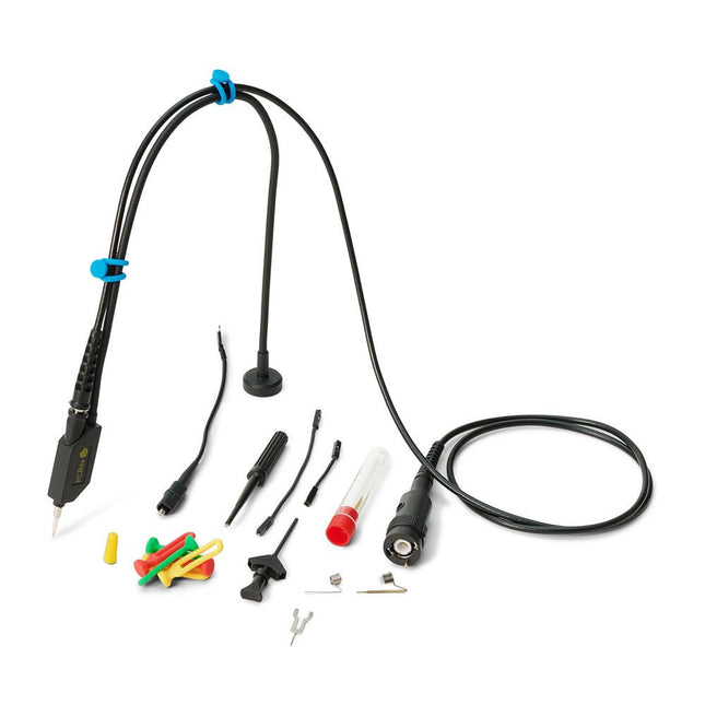
The SQ series of oscilloscope probes also includes more ground options, have probe tip protection, longer cable and support for oscilloscopes with automatic scaling (10:1).
All the loved features of handsfree measurement, exchangeable fine pitch spring tipped test needle, color-coded cable holders and the minimalistic design is maintained to make traditional sized and handheld probes obsolete.
Both length and weight of the SQ probes are perfectly balanced to be used with PCBite PCB holders and base plate which is a must for handsfree function.
Features
Passive 10:1 probe with support for oscilloscopes with automatic scaling
Spring-loaded test needle for fine pitch measurements
Multiple ground options
Color coded cable holders
Probe tip protection
Insulated, can be used handheld
Improved probe holder for handsfree measurement when used with PCBite PCB holders
Included
1x SQ350 350 MHz probe with spring tipped test needle
1x SQ probe holder for handsfree measurement
1x Testhook with detachable cables (5 cm & 10 cm) for convenient ground connection
1x Alligator cable for convenient ground connection
1x Standard ground spring, for handheld measurements at rated bandwidth
1x Unique ground spring, for total handsfree measurements at rated bandwidth
1x Set of color coded cable holders (4 colors)
1x Probe tip protection
1x Extra test needle
Downloads
User Guide SQXX0 Rev1.1
Raspberry Pi cooling is a must. From the simplest passive heat sink, through elaborate fan blowers and even to an exotic water-cooled idea, many options are available.
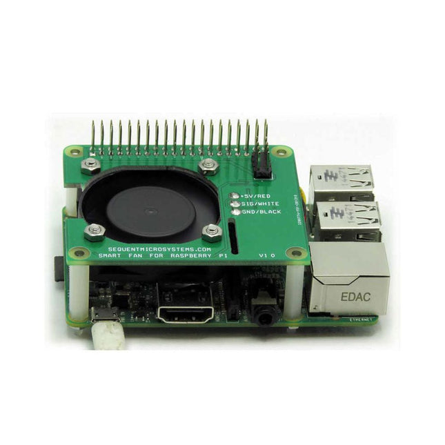
Sequent Microsystems Smart Fan has the form factor of the Raspberry Pi HAT. Its own tinny 32-bit processor receives commands from Raspberry Pi through the I²C interface. A step-up power supply converts the 5 V provided by Raspberry Pi to 12 V, ensuring precise speed control. Using pulse width modulation, it powers the fan just enough to maintain a constant temperature of the Raspberry Pi processor.
The Smart Fan preserves all the GPIO pins, allowing any number of cards to be stacked on top of Raspberry Pi. If another add-on card has to dissipate power, a secondary Smart Fan can be added to the stack.
DIN-Rail Mounting
Together with multiple add-on cards, the Smart Fan can be installed on the DIN-Rail, for sturdy industrial applications.
Stack Level Jumper
Two Smart Fans can be installed on top of each Raspberry Pi. The assumption is that you have one more card in the stack which requires cooling. The bottom side of the Smart Fan has a jumper which needs to be installed on the second fan, in order for the Raspberry Pi to differentiate the two I²C addresses.
Features
40 x 40 x 10 mm fan with 6 CFM airflow
Step-up 12 V power supply for precise fan speed control
PWM Controller modulates the fan to keep constant Pi temperature
Draws less than 100 mA of power
Stackable to itself, 2 fans can be added to Raspberry Pi
Fully stackable allows adding other cards to Raspberry Pi
Uses only I²C interface, leaves full use of all GPIO pins
Super quiet and efficient
Included
Smart Fan HAT
40 x 40 x 10 mm Fan with mounting Screws
Mounting Hardware
Downloads
User's Guide
Open Source Hardware Schematic
2D CAD Drawing
Command line
Python Libraries
Node-Red Nodes
The SEQURE HT140 is a highly versatile 2-in-1 soldering tool that combines the functionality of hot tweezers and a soldering iron. It is specifically engineered for precise SMD soldering and desoldering tasks.
With independent control for single-sided heating, it operates as a traditional soldering iron when fitted with a standard tip. When configured for dual-sided heating, it transforms into hot tweezers – perfect for the efficient and accurate removal of SMD components.
Features
Working Temperature: 50-500°C (122-932°F)
Supports multiple power inputs: PD 3.1/3.0/2.0, QC 3.0/2.0, (5-28 V DC), LiPo batteries, and power adapters.
The HT140 combines hot tweezers and a soldering iron, with independent single- or dual-sided heating. Use it as a soldering iron with a tip, or as hot tweezers for easy SMD desoldering.
Voltage and current can be adjusted based on the power source.
Features dual temperature control, presets, quick temperature increase, and fine-tuning.
128 x 32 OLED screen with adjustable brightness, and orientation. Switchable °C/°F.
High-precision heating element with ±1% accuracy. Melts solder in just 2 seconds.
Smart standby, sleep, and wake-up functions extend tip lifespan and boost efficiency.
Supports temperature calibration and compensation for precise work.
Includes a 1.5 m heat-resistant PD 150 W silicone cable and a sturdy all-metal HT Station.
Swappable tips and adjustable angles for various SMD soldering tasks.
Specifications
Working Voltage
5-28 V DC
Maximum Power
140 W
Working Temperature
50-500°C (122-932°F)
Tin Melting Time
2s
Interface Type
USB-C, DC5525
Power Supply
PD 3.1/3.0/2.0, QC 3.0/2.0, 28 V DC max
Display
128 x 32 OLED
Firmware Upgrade
Yes
Menu Languages
English, Russian, Chinese
Dimensions
160 x 27 x 17.5 mm
Weight
50 g
Included
1x SEQURE HT140 Host
2x HT140-IS Tapered Curved Desoldering Tips
1x HT Station
1x Accessory Package
1x Storage Bag
1x 65 W PD Power Supply (EU, UK & US)
1x 24 W PD Silicone Wire (1.5 m)
1x GND Wire Accessory Kit (1.8 m)
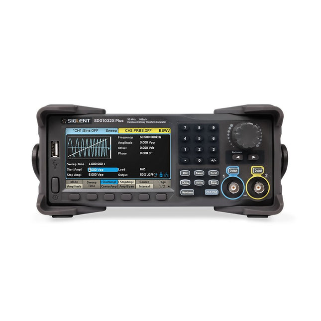
The Siglent SDG1032X Plus is a high-performance dual-channel function/arbitrary waveform generator with a 30 MHz max frequency, 16-bit resolution, and 1 GSa/s sampling rate for superior signal fidelity.
It features TrueArb for low-distortion waveforms, EasyPulse for jitter-free pulses, and robust sequence playback. With ±10 V amplitude, a 4.3" display, and versatile modulation, it's a reliable choice for engineers and researchers.
Features
Dual Channels: Independent output with maximum frequency of 30 MHz
High Sampling Rate: 1 GSa/s for precise waveform generation
High Vertical Resolution: 16-bit resolution for accurate signal reproduction
TrueArb Technology: Generates low-distortion arbitrary waveforms with high fidelity
EasyPulse Technology: Produces jitter-free square and pulse signals with fine control over rise/fall times
Arbitrary Waveform Length: Supports up to 8 Mpts per channel for complex waveform design
Wide Amplitude Range: ±10 V maximum output amplitude
Built-in Modulation Functions: AM, FM, PM, PWM, PSK, FSK, ASK, and more
Multi-Pulse Output: Enables measurement of power equipment switching parameters
PRBS Pattern Generation: Supports up to 40 Mbps for advanced testing needs
Sweep and Burst Modes: Flexible test capabilities with adjustable parameters
Sequence Playback Function: Stores and plays back complex waveforms efficiently
Frequency Counter: Measures frequencies up to 200 MHz with high precision
User-Friendly Display: 4.3" color LCD with a clear interface
Remote Control Support: Built-in WebServer for control via a web browser
Compact Design: Portable and space-saving form factor
Specifications
Bandwidth
30 MHz
Channels
2
Sampling rate
1 GSa/s (4x Interpolation)
Vertical resolution
16 bits (per channel)
Waveform length
8 Mpts
Max. amplitude
±10 V
Display
4.3" color TFT LCD (480 x 272)
Interfaces
USB Host, USB Device, LAN
Dimensions
260 x 107 x 296 mm
Weight
4.35 kg
Included
1x Siglent SDG1032X Plus Arbitrary Function Generator
1x Power Cord
1x USB Cable
1x Guarantee Card
1x Quick Start Guide
Downloads
Datasheet
User Manual
Programming Guide
Software
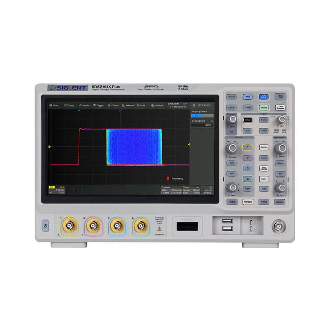
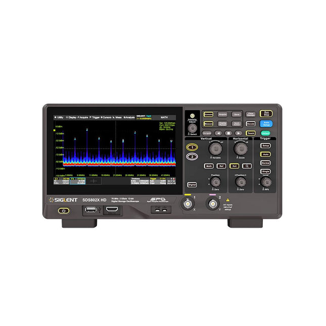
Siglent's SDS2000X Plus series Digital Storage Oscilloscopes are available in bandwidths of 100 MHz, 200 MHz, and 350 MHz, have a maximum sample rate of 2 GSa/s, a maximum record length of 200 Mpts/ch, and up to 4 analog channels + 16 digital channels mixed-signal analysis ability.
The SDS2000X Plus series employs Siglent’s SPO technology with a maximum waveform capture rate of up to 120,000 wfm/s (normal mode, up to 500,000 wfm/s in Sequence mode), 256-level intensity grading display function plus a color temperature display mode. It also employs an innovative digital trigger system with high sensitivity and low jitter. The trigger system supports multiple powerful triggering modes including serial bus triggering. History waveform recording, Sequence acquisition, Search and Navigate functions allow for extended waveform records to be captured, stored, and analyzed. An impressive array of measurement and math capabilities, options for a 50 MHz waveform generator, as well as serial decoding, mask test, bode plot, and power analysis are also features of the SDS2000X Plus. A 10-bit acquisition mode helps to satisfy applications that require more than 8-bit resolution.
The large 10.1’’ capacitive touch screen supports multi-touch gestures, while the remote web control, mouse and external keyboard support greatly improve the operating efficiency of the SDS2000X Plus.
Features
100 MHz, 200 MHz, 350 MHz (upgradable to 500 MHz) models
Real-time sampling rate up to 2 GSa/s
Record length up to 200 Mpts
Serial bus triggering and decoder, supports I²C, SPI, UART, CAN, LIN, CAN FD, FlexRay, I²S and MIL-STD-1553B
Provide 10 bit mode, Vertical and Horizontal Zoom
Capacitive touch screen supports multi-touch gestures
Siglent SDS2000X Plus Oscilloscopes
SDS2102X Plus
SDS2104X Plus
SDS2204X Plus
SDS2354X Plus
Bandwidth
100 MHz
100 MHz
200 MHz
350 MHz
Channels
2
4
4
4
Real-time sampling rate
2 GSa/s
2 GSa/s
2 GSa/s
2 GSa/s
Capture rate
120,000 wfm/s
120,000 wfm/s
120,000 wfm/s
120,000 wfm/s
Memory depth
200 Mpts/ch
200 Mpts/ch
200 Mpts/ch
200 Mpts/ch
Included
Siglent SDS2104X Plus Oscilloscope
Passive probes
Power cord
USB cable
Manual
Downloads
Datasheet
Manual
Quick guide
Manual
Firmware
The Siglent SDS814X HD digital storage oscilloscope is based on 2 GSa/s, 12-bit Analog-Digital Converters and front ends with excellent noise floor performance. With a 100 MHz bandwidth, and a maximum record length of 50 Mpts, and the capability to analyze 4 analog channels alongside 16 digital channels, the SDS814X HD is perfectly suited for mixed signal analysis.
Features
12-bit High Resolution
12-bit Analog-Digital Convertors with sample rate up to 2 GSa/s
Front ends with 70 μVrms noise floor @ 100 MHz bandwidth
2/4 analog channels, up to 700 MHz bandwidth
SPO technology
Waveform capture rate up to 80,000 wfm/s (normal mode), and 500,000 wfm/s (sequence mode)
Supports 256-level intensity grading and color temperature display modes.
Up to 50 Mpts record length
Digital trigger system
Intelligent trigger: Edge, Slope, Pulse width, Window, Runt, Interval, Dropout, Pattern, Video (HDTV supported), Qualified, Nth edge, Delay, Setup/Hold time.
Serial bus triggering and decoder, supports protocols I²C, SPI, UART, CAN, LIN.
Segmented acquisition (Sequence) mode, dividing the maximum record length into multiple segments (up to 80,000), according to trigger conditions set by the user, with a very small dead time between segments to capture the qualifying event.
History waveform record (History) function, the maximum recorded waveform length is 80,000 frames.
Automatic measurements on 50+ parameters, supports statistics with histogram, track, trend, Gating measurement, and measurements on Math, History and Ref.
4 Math traces (2 Mpts FFT, addition, subtraction, multiplication, division, integration, differential, square root, etc.), supports formula editor.
Abundant data analysis functions such as Search, Navigate, Counter, Bode plot and Power Analysis
High Speed hardware-based Mask Test function, with Mask Editor tool for creating user-defined masks
16 digital channels (optional)
25 MHz waveform generator (optional)
7" TFT-LCD display with 1024 x 600 resolution; Capacitive touch screen supports multi-touch gestures.
Interfaces include: USB Hosts, USB Device (USBTMC), LAN (VXI-11/Telnet/Socket), Pass/Fail, Trigger Out
Built-in web server supports remote control over the LAN port using a web browser. Supports SCPI remote control commands. Supports external mouse and keyboard. Supports NTP.
Specifications
Analog Channels
4
Bandwidth
100 MHz
Vertical resolution
12-bit
Sample rate (Max.)
One channel mode: 2 GSa/sTwo channel mode: 1 GSa/sFour channel mode: 500 MSa/s
Memory depth (Max.)
One channel mode: 50 Mpts/chTwo channel mode: 25 Mpts/chFour channel mode: 10Mpts/ch
Waveform capture rate (Max.)
Normal mode: 80,000 wfm/sSequence mode: 500,000 wfm/s
Trigger type
Edge, Slope, Pulse width, Window, Runt, Interval, Dropout, Pattern, Video, Qualified, Nth edge, Delay, Setup/Hold time, Serial
Serial trigger and decode (Standard)
I²C, SPI, UART, CAN, LIN
Measurement
50+ parameters, statistics, histogram, trend, and track supported
Math
4 traces 2 Mpts FFT, Filter, +, -, x, ÷, ∫dt, d/dt, √, Identity, Negation, Absolute, Sign, ex, 10x, ln, lg, Interpolation, MaxHold, MinHold, ERES, Average. Supports formula editor
Data analysis
Search, Navigate, History, Mask Test, Counter, Bode plot, and Power Analysis
Digital channel (optional)
16-channel; maximum sample rate up to 1 GSa/s; record length up to 10 Mpts
USB AWG module (option)
One channel, 25 MHz, sample rate of 125 MHz, wave length of 16 kpts, isolated output
I/O
2x USB 2.0 Host, USB 2.0 Device, 10/100 M LAN, Auxiliary output (TRIG OUT, PASS/FAIL), SBUS (Siglent MSO)
Probe (Standard)
Passive probe PB470 for each channel
Display
7 TFT-LCD with capacitive touch screen (1024x600)
Included
1x Siglent SDS814X Oscilloscope
4x Passive probe (100 MHz) PP510
1x Power cord (EU)
1x USB cable
1x Certificate of calibration
1x Quick start
Downloads
Datasheet
Manual
Programming guide
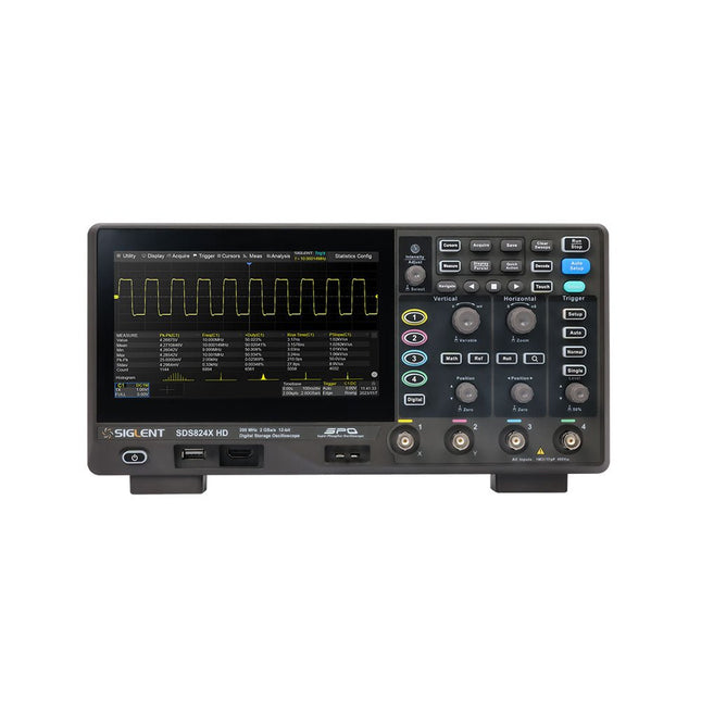
The Siglent SDS822X HD digital storage oscilloscope is based on 2 GSa/s, 12-bit Analog-Digital Converters and front ends with excellent noise floor performance. With a 200 MHz bandwidth, and a maximum record length of 100 Mpts, and the capability to analyze 2 analog channels alongside 16 digital channels, the SDS822X HD is perfectly suited for mixed signal analysis.
Features
12-bit High Resolution
12-bit Analog-Digital Convertors with sample rate up to 2 GSa/s
Front ends with 70 μVrms noise floor @ 200 MHz bandwidth
2/4 analog channels, up to 700 MHz bandwidth
SPO technology
Waveform capture rate up to 120,000 wfm/s (normal mode), and 500,000 wfm/s (sequence mode)
Supports 256-level intensity grading and color temperature display modes.
Up to 50 Mpts record length
Digital trigger system
Intelligent trigger: Edge, Slope, Pulse width, Window, Runt, Interval, Dropout, Pattern, Video (HDTV supported), Qualified, Nth edge, Delay, Setup/Hold time.
Serial bus triggering and decoder, supports protocols I²C, SPI, UART, CAN, LIN.
Segmented acquisition (Sequence) mode, dividing the maximum record length into multiple segments (up to 80,000), according to trigger conditions set by the user, with a very small dead time between segments to capture the qualifying event.
History waveform record (History) function, the maximum recorded waveform length is 80,000 frames.
Automatic measurements on 50+ parameters, supports statistics with histogram, track, trend, Gating measurement, and measurements on Math, History and Ref.
4 Math traces (2 Mpts FFT, addition, subtraction, multiplication, division, integration, differential, square root, etc.), supports formula editor.
Abundant data analysis functions such as Search, Navigate, Counter, Bode plot and Power Analysis
High Speed hardware-based Mask Test function, with Mask Editor tool for creating user-defined masks
16 digital channels (optional)
25 MHz waveform generator (optional)
7" TFT-LCD display with 1024 x 600 resolution; Capacitive touch screen supports multi-touch gestures.
Interfaces include: USB Hosts, USB Device (USBTMC), LAN (VXI-11/Telnet/Socket), Pass/Fail, Trigger Out
Built-in web server supports remote control over the LAN port using a web browser. Supports SCPI remote control commands. Supports external mouse and keyboard. Supports NTP.
Specifications
Analog Channels
2
Bandwidth
200 MHz
Vertical resolution
12-bit
Sample rate (Max.)
One channel mode: 100 Mpts/chTwo channel mode: Mpts/chFour channel mode: 25 Mpts/ch
Memory depth (Max.)
One channel mode: 50 Mpts/chTwo channel mode: 25 Mpts/ch
Waveform capture rate (Max.)
Normal mode: 120,000 wfm/sSequence mode: 500,000 wfm/s
Trigger type
Edge, Slope, Pulse width, Window, Runt, Interval, Dropout, Pattern, Video, Qualified, Nth edge, Delay, Setup/Hold time, Serial
Serial trigger and decode (Standard)
I²C, SPI, UART, CAN, LIN
Measurement
50+ parameters, statistics, histogram, trend, and track supported
Math
4 traces 2 Mpts FFT, Filter, +, -, x, ÷, ∫dt, d/dt, √, Identity, Negation, Absolute, Sign, ex, 10x, ln, lg, Interpolation, MaxHold, MinHold, ERES, Average. Supports formula editor
Data analysis
Search, Navigate, History, Mask Test, Counter, Bode plot, and Power Analysis
Digital channel (optional)
16-channel; maximum sample rate up to 1 GSa/s; record length up to 10 Mpts
USB AWG module (option)
One channel, 25 MHz, sample rate of 125 MHz, wave length of 16 kpts, isolated output
I/O
2x USB 2.0 Host, USB 2.0 Device, 10/100 M LAN, Auxiliary output (TRIG OUT, PASS/FAIL), SBUS (Siglent MSO)
Probe (Standard)
Passive probe PB470 for each channel
Display
7 TFT-LCD with capacitive touch screen (1024x600)
Included
1x Siglent SDS822X Oscilloscope
2x Passive probe (200 MHz) PP520
1x Power cord (EU)
1x USB cable
1x Certificate of calibration
1x Quick start
Downloads
Datasheet
Manual
Programming guide
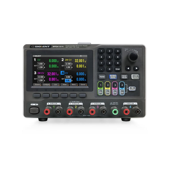
The Siglent SPD4121X is a 4-channel DC Linear Programmable Power Supply equipped with a 4.3-inch TFT-LCD display, friendly human-machine interface, and excellent performance indicators. Real-time waveform display provides engineers with an informative user interface.
SPD4121X offers a total output power of 285 W with a resolution of 1 mV/1 mA. The maximum voltage and current for each channel are as follows:
CH1: 15 V/1.5 A
CH2: 12 V/10 A
CH3: 12 V/10 A
CH4: 15 V/1.5 A
Features
Rated output power: 285 W
Rated voltage: 32 V, 12 V, 30 V
Up to four high-precision power supplies with independent controllable outputs, supporting CH2 and CH3 series and parallel connections
Clear graphical interface with waveform and timer display modes
5-digit voltage and current display with minimum resolution of 1 mV, 1 mA
Fast output response time: <50us
The high current channel support remote voltage compensation sense function. The maximum compensation voltage is 0.6 V
Overvoltage protection and overcurrent protection or safe and accurate operation
Equipped with a 4.3-inch TFT-LCD display (480 x 272 resolution)
USB and LAN standard communication
USB-GPIB module is optional
Excellent channel density with up to 4 channels in a 3U half rack package
Internal data storage for setups and parameters
Embedded Web Server with instrument communication that doesn’t require software installation
Fully SCPI programming command set support as well as a LabView driver for remote control and system automation
Specifications
SPD4323X
SPD4121X
SPD4306X
Channel Output
CH1: Voltage 0 to 6 V Current 0 to 3.2 ACH2: Voltage 0 to 32 V Current 0 to 3.2 ACH3: Voltage 0 to 32 V Current 0 to 3.2 ACH4: Voltage 0 to 6 V Current 0 to 3.2 A
CH1: Voltage 0 to 15 V Current 0 to 1.5 ACH2: Voltage 0 to 12 V Current 0 to 10 ACH3: Voltage 0 to 12 V Current 0 to 10 ACH4: Voltage 0 to 15 V Current 0 to 1.5 A
CH1: Voltage 0 to 15 V Current 0 to 1.5 ACH2: Voltage 0 to 30 V Current 0 to 6 ACH3: Voltage 0 to 30 V Current 0 to 6 ACH4: Voltage 0 to 15 V Current 0 to 1 A
Resolution
1 mV, 1 mA
1 mV, 1 mA
1 mV, 1 mA
Setting Accuracy
Voltage: ±(0.03% of reading+10) mV, Current: ±(0.3% of reading+10) mA
Voltage: ±(0.03% of reading+10) mV, Current: ±(0.3% of reading+10) mA
Voltage: ±(0.03% of reading+10) mV, Current: ±(0.3% of reading+10) mA
Readback Accuracy
Voltage: ±(0.03% of reading+10) mV, Current: ±(0.3% of reading+10) mA
Voltage: ±(0.03% of reading+10) mV, Current: ±(0.3% of reading+10) mA
Voltage: ±(0.03% of reading+10) mV, Current: ±(0.3% of reading+10) mA
Display
4.3" TFT-LCD 5-digit voltage and current display
4.3" TFT-LCD 5-digit voltage and current display
4.3" TFT-LCD 5-digit voltage and current display
Output power
240 W
285 W
400 W
Included
1x Siglent SPD4121X Power Supply
1x Power cord (EU)
1x Output test cord (3 A)
1x USB cable
1x Quick start guide
Downloads
Datasheet
Manual
Quick start
The Siglent SPD4306X is a 4-channel DC Linear Programmable Power Supply equipped with a 4.3-inch TFT-LCD display, friendly human-machine interface, and excellent performance indicators. Real-time waveform display provides engineers with an informative user interface.
SPD4306X offers a total output power of 400 W with a resolution of 1 mV/1 mA. The maximum voltage and current for each channel are as follows:
CH1: 15 V/1.5 A
CH2: 30 V/6 A
CH3: 30 V/6 A
CH4: 15 V/1 A
Features
Rated output power: 400 W
Rated voltage: 32 V, 12 V, 30 V
Up to four high-precision power supplies with independent controllable outputs, supporting CH2 and CH3 series and parallel connections
Clear graphical interface with waveform and timer display modes
5-digit voltage and current display with minimum resolution of 1 mV, 1 mA
Fast output response time: <50us
The high current channel support remote voltage compensation sense function. The maximum compensation voltage is 0.6 V
Overvoltage protection and overcurrent protection or safe and accurate operation
Equipped with a 4.3-inch TFT-LCD display (480 x 272 resolution)
USB and LAN standard communication
USB-GPIB module is optional
Excellent channel density with up to 4 channels in a 3U half rack package
Internal data storage for setups and parameters
Embedded Web Server with instrument communication that doesn’t require software installation
Fully SCPI programming command set support as well as a LabView driver for remote control and system automation
Specifications
SPD4323X
SPD4121X
SPD4306X
Channel Output
CH1: Voltage 0 to 6 V Current 0 to 3.2 ACH2: Voltage 0 to 32 V Current 0 to 3.2 ACH3: Voltage 0 to 32 V Current 0 to 3.2 ACH4: Voltage 0 to 6 V Current 0 to 3.2 A
CH1: Voltage 0 to 15 V Current 0 to 1.5 ACH2: Voltage 0 to 12 V Current 0 to 10 ACH3: Voltage 0 to 12 V Current 0 to 10 ACH4: Voltage 0 to 15 V Current 0 to 1.5 A
CH1: Voltage 0 to 15 V Current 0 to 1.5 ACH2: Voltage 0 to 30 V Current 0 to 6 ACH3: Voltage 0 to 30 V Current 0 to 6 ACH4: Voltage 0 to 15 V Current 0 to 1 A
Resolution
1 mV, 1 mA
1 mV, 1 mA
1 mV, 1 mA
Setting Accuracy
Voltage: ±(0.03% of reading+10) mV, Current: ±(0.3% of reading+10) mA
Voltage: ±(0.03% of reading+10) mV, Current: ±(0.3% of reading+10) mA
Voltage: ±(0.03% of reading+10) mV, Current: ±(0.3% of reading+10) mA
Readback Accuracy
Voltage: ±(0.03% of reading+10) mV, Current: ±(0.3% of reading+10) mA
Voltage: ±(0.03% of reading+10) mV, Current: ±(0.3% of reading+10) mA
Voltage: ±(0.03% of reading+10) mV, Current: ±(0.3% of reading+10) mA
Display
4.3" TFT-LCD 5-digit voltage and current display
4.3" TFT-LCD 5-digit voltage and current display
4.3" TFT-LCD 5-digit voltage and current display
Output power
240 W
285 W
400 W
Included
1x Siglent SPD4306X Power Supply
1x Power cord (EU)
1x Output test cord (3 A)
1x USB cable
1x Quick start guide
Downloads
Datasheet
Manual
Quick start
The Siglent SPD4323X is a 4-channel DC Linear Programmable Power Supply equipped with a 4.3-inch TFT-LCD display, friendly human-machine interface, and excellent performance indicators. Real-time waveform display provides engineers with an informative user interface.
SPD4323X offers a total output power of 240 W with a resolution of 1 mV/1 mA. The maximum voltage and current for each channel are as follows:
CH1: 6 V/3.2 A
CH2: 32 V/3.2 A
CH3: 32 V/3.2 A
CH4: 6 V/3.2 A
Features
Rated output power: 240 W
Rated voltage: 32 V, 12 V, 30 V
Up to four high-precision power supplies with independent controllable outputs, supporting CH2 and CH3 series and parallel connections
Clear graphical interface with waveform and timer display modes
5-digit voltage and current display with minimum resolution of 1 mV, 1 mA
Fast output response time: <50us
The high current channel support remote voltage compensation sense function. The maximum compensation voltage is 0.6 V
Overvoltage protection and overcurrent protection or safe and accurate operation
Equipped with a 4.3-inch TFT-LCD display (480 x 272 resolution)
USB and LAN standard communication
USB-GPIB module is optional
Excellent channel density with up to 4 channels in a 3U half rack package
Internal data storage for setups and parameters
Embedded Web Server with instrument communication that doesn’t require software installation
Fully SCPI programming command set support as well as a LabView driver for remote control and system automation
Specifications
SPD4323X
SPD4121X
SPD4306X
Channel Output
CH1: Voltage 0 to 6 V Current 0 to 3.2 ACH2: Voltage 0 to 32 V Current 0 to 3.2 ACH3: Voltage 0 to 32 V Current 0 to 3.2 ACH4: Voltage 0 to 6 V Current 0 to 3.2 A
CH1: Voltage 0 to 15 V Current 0 to 1.5 ACH2: Voltage 0 to 12 V Current 0 to 10 ACH3: Voltage 0 to 12 V Current 0 to 10 ACH4: Voltage 0 to 15 V Current 0 to 1.5 A
CH1: Voltage 0 to 15 V Current 0 to 1.5 ACH2: Voltage 0 to 30 V Current 0 to 6 ACH3: Voltage 0 to 30 V Current 0 to 6 ACH4: Voltage 0 to 15 V Current 0 to 1 A
Resolution
1 mV, 1 mA
1 mV, 1 mA
1 mV, 1 mA
Setting Accuracy
Voltage: ±(0.03% of reading+10) mV, Current: ±(0.3% of reading+10) mA
Voltage: ±(0.03% of reading+10) mV, Current: ±(0.3% of reading+10) mA
Voltage: ±(0.03% of reading+10) mV, Current: ±(0.3% of reading+10) mA
Readback Accuracy
Voltage: ±(0.03% of reading+10) mV, Current: ±(0.3% of reading+10) mA
Voltage: ±(0.03% of reading+10) mV, Current: ±(0.3% of reading+10) mA
Voltage: ±(0.03% of reading+10) mV, Current: ±(0.3% of reading+10) mA
Display
4.3" TFT-LCD 5-digit voltage and current display
4.3" TFT-LCD 5-digit voltage and current display
4.3" TFT-LCD 5-digit voltage and current display
Output power
240 W
285 W
400 W
Included
1x Siglent SPD4323X Power Supply
1x Power cord (EU)
1x Output test cord (3 A)
1x USB cable
1x Quick start guide
Downloads
Datasheet
Manual
Quick start
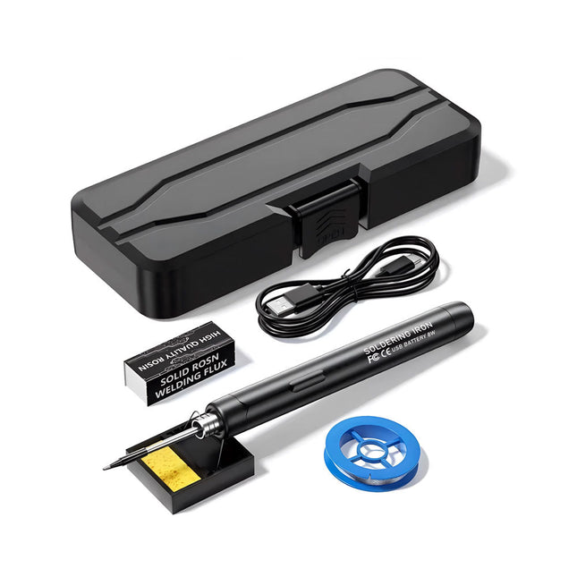
The Smart USB Soldering Iron Kit is a compact, cordless solution designed for precision and portability. Featuring intelligent three-speed temperature control (300-450°C) with an easy-to-read LED display, it heats up in just 10 seconds and melts solder in as little as 6 seconds.
The 1000 mAh rechargeable battery delivers up to 30 minutes of continuous use, making it ideal for quick repairs, electronics projects, and DIY tasks. With a plug-and-play, replaceable tip and a high-temperature-resistant insulated shell, it’s safe, user-friendly, and perfect for both beginners and professionals on the go.
Features
Three-Speed Intelligent Temperature Adjustment: Features an LED display screen with adjustable temperatures between 300-450°C (572-842°F). Easily switch between Celsius and Fahrenheit.
Integrated Plug-In Soldering Iron Tip: Plug-and-play design. The tip can be replaced by simply unscrewing it, ensuring quick and convenient operation.
Safe and Durable Design: High-temperature-resistant, insulated shell for enhanced safety during use.
Battery Capacity: Equipped with a rechargeable 1000 mAh battery that supports up to 30 minutes of continuous operation on a full charge – ideal for everyday tasks.
Efficient Performance: 8 W power with an integrated heating core for rapid heat-up. Melts tin in just 6 seconds, providing excellent thermal conductivity.
Easy to Use: After powering on via USB, set your desired temperature. The soldering iron heats up in 10 seconds. Once finished, place the tip on the stand—it cools down within 1 minute. Perfect for beginners, hobbyists, basic home repairs, and training engineers.
Cordless Innovation: This cordless soldering kit includes a built-in rechargeable lithium-ion battery, eliminating the need for cables. Versatile use for circuit board soldering, electrical repairs, jewelry making, metal crafts, computer maintenance, and DIY projects.
Specifications
Adjustable Temperature: 300-450°C (572-842°F)
Tin Melting Time: <15 seconds
Working Voltage: 5 V
Power Output: 8 W
Battery Capacity: 1000 mAh
Auto Sleep Function: Activates after 10 minutes of inactivity
Charging Time: Approx. 90 minutes
Battery Life: Up to 30 minutes continuous use
Charging Interface: USB-C
Main Material: Aluminum alloy
Dimensions: 190 x 16 mm (7.4 x 0.6")
Included
1x USB Soldering Iron
1x Soldering Tip
1x Soldering Rosin
1x Soldering Iron Holder (with Sponge)
1x USB-C Charging Cable
1x Solder Wire
1x Storage Box
SMD Magazines are injection-molded containers and a great way to organize and consume SMD parts. They are custom built to store components and present them for picking. They can load up to 12-mm-wide, 9.5-mm tall tapes. They replace those hard-to-find plastic bags while being an excellent source of parts to pick and placing using Pixel Pump.
Each SMD-Magazine Rail presents up to eight magazines at the perfect angle for you to pick and place their components using Pixel Pump. You can also use these rails to group components for specific projects. They are equipped with non-slip rubber feet and weighted for extra stability.
An SMD Magazine rail holds up to eight SMD Magazines. A given rail can be used to hold a project-specific set of magazines indefinitely. Magazines are held at a right angle, ready to be picked and placed by Pixel Pump.
Each SMD-Magazine Rail presents up to eight magazines at the perfect angle for you to pick and place their components using Pixel Pump. You can also use these rails to group components for specific projects. They are equipped with non-slip rubber feet and weighted for extra stability.
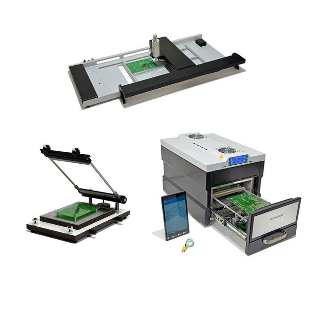
The SMD Starter I prototype production line consists of the stencil printer TSD240, the SMD placement device PlaceMAN and the reflow oven 3LHR10. Stencil printer SD240 (+ Metal Squeegee 155 mm) Stencil size: max. 175 x 255 mm PCB size: max. 180 x 240 mm Size: 410 x 270 x 110 mm Weight: 6.7 kg incl. metal squeegee 155 mm incl. 8 magnets to hold the PCB, 6 of them with M3 grub screw Manual SMD pick-and-place device PlaceMAN for standard components incl. vacuum pump (without feeders, camera, monitor and dispenser) Equipped with smooth-running placement arm, placement head with one-hand operation, rotation of the Z-axis and automatic vacuum switch-off, incl. PCB holder, vacuum unit and 2 placement needles with rubber suction cups. Capacity of feeder (not included) 2x feeder cassette for 10 x 8 mm wheels left 4x feeder cassette for rod feeders for 5 rods each Further feeding systems are possible within the assembly area, e.g. strip-feeder plug-in system Dimensions Base unit (LxWxH): 765 x 390 x 210 mm With feeder cassette for 10 x 8 mm rolls (LxWxH): 765 x 390 x 210 mm With feeder cassette for 10 x 8 mm rolls and feeder cassette for rod feeder (LxWxH): 765 x 430 x 210 mm (height may vary due to rod length) With feeder cassette for 10 x 8 mm rolls incl. holder for 10 rolls and feeder cassette for rod feeder (LxWxH): 765 x 430 x 210 mm (height may vary due to rod length) Specifications Weight of basic unit: approx. 6 kg Axis travel (x,y,z): 470 x 230 x 15 mm Max. working area: 380 x 240 mm Max. PCB size: 230 x 360 mm Power supply: 230/12 V, 800 mA Power supply vacuum pump: 230 V, 6 W 3LHR10 Reflow Oven (programmable for lead-free soldering with manual drawer and tablet control) Reflow oven with IR and convection heating. Forced hot air convection ensures a uniform temperature profile throughout the chamber. After manually opening the door, the fans are turned on and the soldered PCB is quickly cooled. Small reflow oven with manual door Industry 4.0 ready, Bluetooth communication + tablet IR + convection heating Android application to connect to tablet or smartphone 100 different user programs Delivery content: 3LHR10, tablet with app, protective cover for tablet, 4 PCB holders, external thermocouple, manual at tablet Application Connect the oven to the power supply and connect the optionally available extraction system (3LFE10S) to the exhaust air nozzle. After the first turn on, the oven will search for a tablet or smartphone. When both are connected to the Android app, choose the programming of the oven. Here, programmable temperature and preheating time as well as temperature and other data are to be set. Register with the tablet to use the full scope of the software. If the oven is already programmed, the user can control the operation with buttons and display at the front panel. When the reflow process is complete, an audible signal sounds. A signal is also displayed on the tablet/smartphone. The drawer must now be opened manually. The Android application displays process status, time and temperature or other information. Specifications Power supply: 230 V, 50 Hz Maximum power: 3100 W Temperatures: 50-260°C Dimensions: 510 x 370 x 340 mm Maximum weight: 16 kg Grid dimensions: 350 x 220 mm Maximum dimensions of the printed circuit board: 300 x 200 mm Maximum component height on the PCB: 50 mm at the top, 30 mm at the bottom Scope of delivery Stencil printer TSD240 SMD placement device PlaceMAN Reflow oven 3LHR10
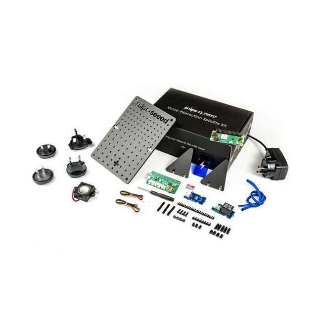
The Voice Interaction Satellite Kit can extend the reach of your base station to each room in your house and enable you to interact with the hardware based on where you issue your commands! You can arrange multiple Satellite Kits throughout your home to add new functionality to Base kit or any other smart speaker, extending your voice control across several rooms.
The Voice Interaction Satellite Kit is powered by a Raspberry Pi Zero W and the ReSpeaker 2-Mics Pi HAT. Along with the kit comes a speaker, a Grove - Temperature Humidity Sensor (SHT31) sensor, a Grove Relay, and a pegboard to hang it on a wall or create a nifty stand.
Note
All Satellite Kits require a Base kit or Raspberry Pi in order to operate as intended.
Easy to solder real time watch kit with a unique laser cut acrylic casing. Four individual acrylic parts cut to fit the internal PCB, battery and switch perfectly. Included is a velcro wrist band. After soldering the Solder:Time, the watch is built by stacking the acrylic parts with the PCB and holding it together with the included screws.
The Solder:Time was designed to be a wrist watch. It doesn't have to be limited to living on your wrist, you could also use it as a badge or desk clock.
Features
Great looking laser cut acrylic case
Unique watch
Easy to solder
Stand alone project – no computer or other programmer required. Just solder it and it's ready!
On board Dallas DS1337+ Real Time Clock (RTC) for super accurate time keeping
Jumper (on bottom) for always on use.
Hackable: Programming and I²C pads labeled on bottom
Clear front and back casing to show the internal electronics
Adjustable wrist band
Can be also be worn as a badge with optional badge clip.
Long lasting battery, with special LED lighting method and very low power processor sleeping.
Included
Solder:Time PCB with all of the electronics
Laser cut acrylic casing with four screws
Easy to use Velcro type wrist band (long enough for huge wrists, trim-able for smaller ones.
CR2032 Battery
Downloads
Documentation
Required
Soldering Iron, solder and wire snips.
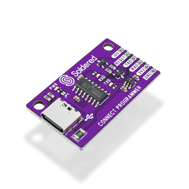
The Soldered CONNECT Programmer is designed to make programming boards based on ESP8266 and ESP32 microcontrollers extremely simple. It contains all the necessary electronics and logic, allowing programming to be done by simply plugging a USB cable into the CONNECT Programmer and connecting it to the programming header. The onboard circuitry handles timing and signal sequencing automatically, placing the ESP microcontroller into bootloader mode without the need for manual intervention.
Features
IC: CH340
Pin layout: GPIO0, RESET, RX, TX, 3V3, GND
LEDs: RX, TX, power
Interface: USB-C
Dimensions: 38 x 22 mm
Downloads
Datasheet
GitHub
This set contains 4 soldering tips for the temperature-controlled digital soldering station ZD-8961-A. Included 1x Soldering tip N8-1 1x Soldering tip N8-2 1x Soldering tip N8-3 1x Soldering tip N8-4
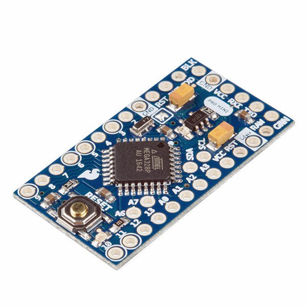
The Arduino Pro Mini is a microcontroller board based on the ATmega328P.
It has 14 digital input/output pins (of which 6 can be used as PWM outputs), 6 analog inputs, an on-board resonator, a reset button, and holes for mounting pin headers. A six pin header can be connected to an FTDI cable or SparkFun breakout board to provide USB power and communication to the board.
The Arduino Pro Mini is intended for semi-permanent installation in objects or exhibitions. The board comes without pre-mounted headers, allowing the use of various types of connectors or direct soldering of wires. The pin layout is compatible with the Arduino Mini.
The Arduino Pro Mini was designed and is manufactured by SparkFun Electronics.
Specifications
Microcontroller
ATmega328P
Board Power Supply
5-12 V
Circuit Operating Voltage
5 V
Digital I/O Pins
14
PWM Pins
6
UART
1
SPI
1
I²C
1
Analog Input Pins
6
External Interrupts
2
DC Current per I/O Pin
40 mA
Flash Memory
32 KB of which 2 KB used by bootloader
SRAM
2 KB
EEPROM
1 KB
Clock Speed
16 MHz
Dimensions
18 x 33.3 mm (0.7 x 1.3")
Downloads
Eagle files
Schematics
The flexibility of the Artemis module starts with SparkFun's Arduino core. You can program and use the Artemis module just like you would an Uno or any other Arduino. The time to first blink is just 5 minutes away! We built the core from the ground up, making it fast and as lightweight as possible.
Next is the module itself. Measuring 10 x 15 mm, the Artemis module has all the support circuitry you need to use the fantastic Ambiq Apollo3 processor in your next project. We're proud to say the SparkFun Artemis module is the first open-source hardware module with the design files freely and easily available. We've carefully designed the module so that implementing Artemis into your design can be done with low-cost 2-layer PCBs and 8mil trace/space.
Made in the USA at SparkFun's Boulder production line, the Artemis module is designed for consumer-grade products. This truly differentiates the Artemis from its Arduino brethren. Ready to scale your product? The Artemis will grow with you beyond the Uno footprint and Arduino IDE. Additionally, the Artemis has an advanced HAL (hardware abstraction layer), allowing users to push the modern Cortex-M4F architecture to its limit.
The SparkFun Artemis Module is fully FCC/IC/CE certified and is available in full tape and reel quantities. With 1M flash and 384k RAM, you'll have plenty of room for your code. The Artemis module runs at 48MHz with a 96MHz turbo mode available and with Bluetooth to boot!
Reinforcing its commitment to widening the accessibility to and innovation in the area of deep learning, NVIDIA has created a free, self-paced, online Deep Learning Institute (DLI) course, “Getting Started on AI with Jetson Nano.” The course's goal is to build foundational skills to enable anyone to get creative with the Jetson Developer Kit. Please be aware that this kit is for those who already own a Jetson Nano Developer Kit and want to join the DLI Course. A Jetson Nano is not included in this kit.
Included in this kit is everything you will need to get started in the “Getting Started on AI with Jetson Nano” (except for a Jetson Nano, of course), and you will learn how to
Set up your Jetson Nano and camera
Collect image data for classification models
Annotate image data for regression models
Train a neural network on your data to create your own models
Run inference on the Jetson Nano with the models you create
The NVIDIA Deep Learning Institute offers hands-on training in AI and accelerated computing to solve real-world problems. Developers, data scientists, researchers, and students can get practical experience powered by GPUs in the cloud and earn a competency certificate to support professional growth. They offer self-paced, online training for individuals, instructor-led workshops for teams, and downloadable course materials for university educators.
Included
32 GB microSD Card
Logitech C270 Webcam
Power Supply 5 V, 4 A
USB Cable - microB (Reversible)
2-Pin Jumper
Please note: Jetson Nano Developer Kit not included.