Products
-
Elektor Digital 303 Circuits (E-book)
Like its predecessors in the 300 series of electronics projects books, 303 Circuits is aimed at the active electronics enthusiast, professional or amateur. Since the series was started in the early 1980s, many thousands of readers have found in these books that new approach, new concept, or new circuit they were looking for. In 303 Circuits you will find new ideas, new concepts and new circuits covering the gamut of electronics. The book is arranged in subject sections to make it easier for you to find the circuit or idea you are looking for.
€ 29,95
Members: € 26,96
-
Elektor Digital 309 Circuits (E-book)
The present tenth edition of the popular ʻ30x Circuitsʼ series of books once again contains a comprehensive variety of circuits, sub-circuits, tips and tricks and design ideas for electronics. These 309 Circuits again offer a representative indication of present-day electronics. Regular ʻ30x seriesʼ enthusiasts will no doubt know what to expect: 309 Circuits contains many fully elaborated electronics projects. In addition, there are numerous ideas, each of which with a potential for use in your own research, projects and applications. Among many other inspiring topics, the following categories are well presented in this book: test & measurement; RF (radio); computers and peripherals; audio & video; hobby and modelling; microcontrollers; home & garden; power supplies & battery chargers; etcetera. 309 Circuits has been compiled from the contents of Elektor Electronics' Summer Circuits editions for the years 2003, 2004 and 2005. Summer Circuits is the annual double issue of Elektor Electronics magazine covering the months of July and August.
€ 29,95
Members: € 26,96
-
Elektor Digital 310 Circuits (E-book)
310 Circuits – is the 11th volume in Elektor’s renowned ‘Three Hundred’ series. 310 circuits, tips and design ideas in one book form a treasure trove for every area of electronics: audio and video, hobby and modelling, RF techniques, home and garden, test and measurement, microcontrollers, computer hardware and software, power supplies and chargers – plus of course everything else that does not seem to belong in any of these categories. 310 Circuits – contains many complete solutions as well as useful starting points for your own projects. Both categories and anything in between represent a veritable fountain of inspiration for cultivating your own ideas and learning about electronics. 310 Circuits – is a compilation of articles from ‘Summer Circuits’ editions for the years 2006, 2007 and 2008. ‘Summer Circuits’ covers the publication months July and August of Elektor magazine. 310 Circuits – is a must-have book for every creative electronics enthusiast, be it professional, enthusiast or student. 310 Circuits – for the first time has a section exclusively on robots and robotics.
€ 29,95
Members: € 26,96
-
Elektor Digital 311 Circuits (E-book)
311 Circuits is the twelfth book in Elektor’s celebrated ‘300’ series. An immense source of inspiration for all electronics enthusiasts and professionals, this book deserves a place not far from the workbench. This book contains circuits, design ideas, tips and tricks from all areas of electronics: audio & video, computers & microcontrollers, radio, hobby & modelling, home & garden, power supplies & batteries, test & measurement, software, not forgetting a section ‘miscellaneous’ for everything that doesn’t fit in one of the other categories. 311 Circuits presents complete solutions for numerous problems, as well as starting points for your own creations. 311 Circuits has been compiled from the 2009, 2010 and 2011 ‘Summer Circuits’ double editions of Elektor magazine. The book is mostly based on readers’ contributions, supplemented by circuits engineered and developed in the Elektor Labs.
€ 29,95
Members: € 26,96
-
Elektor Digital 3D Modeling and Printing for Electronics (E-book)
Learn to 3D Model & 3D Print with Tinkercad With this book and the complementary videos, you’ll be 3D printing in no time at all. This course is meant to have you make casings for electronic components but also goes into optimizing your print technique as well as adding a little flair to your 3D creations. The course is perfect for you if you just bought your (first) 3D printer and want to print your own designs as soon as possible while also being able to get more background information. You’ll get to know the workings of a 3D printer and what software to use to model your object, not forgetting to make it print perfectly. We’ll even use the magic of 3D printing to create things that appear impossible to make (this fast and simple) with any other rapid-prototyping technique. At the end of this course, it’ll be second nature for you to design an object for 3D printing and fine-tune your print-setting to get the perfect print! The book includes the following 7 video tutorials: Introduction Basic 3D modeling for 3D printing Modeling a casing Post-processing Pushing the limits Movable parts Snap fits
€ 32,95
Members: € 29,66
-
Elektor Digital 50 PIC Microcontroller Projects (E-book)
This book contains 50 fun and exciting projects for PIC microcontrollers such as a laser alarm, USB teasing mouse, eggtimer, youth repellent, soundswitch, capacitive liquid level gauge, 'finger in the water' sensor, guarding a room using a camera, mains light dimmer (110-240 volts), talking microcontroller and much more. Several different techniques are discussed such as relay, alternating current control including mains, I²C, SPI, RS232, USB, pulse width modulation, rotary encoder, interrupts, infrared, analog-digital conversion (and the other way around), 7-segment display and even CAN bus. You can use this book to build the projects for your own use. The clear explanations, schematics and even pictures of each project make this a fun activity. For each project the theory is discussed and why the project has been executed in that particular way. That means you can also use this book as a studybook, or as basis for larger and more complicated projects. All projects use a breadboard so modification and expansion is easy. Three PIC microcontrollers are used, the 16f877A, 18f4455 and 18f4685. It is also discussed how you can migrate your project from one microcontroller to another – 15 types are supported - including two example projects. All software that is used in this book can be downloaded for free. That also applies to the open source programming language JAL. This powerful and yet easy to learn language is used by hobbyists as well as professionals. This book can also be used as a reference guide. It explains all JAL commands, as well as the expansion libraries. Using the index you can easily find example projects that illustrate the use of these commands. Even when you have built all projects in this book you will still want to keep it within arm's reach.
€ 34,95
Members: € 31,46
-

Elektor Bundles 555 Timer Projects (Bundle)
This bundle is all about designing projects based on the 555 timer IC. The book features over 45 fully tested and documented projects. Together with the kit, which contains more than 130 through-hole components, you can build all the projects described on a breadboard. The setup also makes it easy to modify and experiment with the projects. Over 45 Builds for the Legendary 555 Chip (and the 556, 558) Some of the projects in the book are: Alternately Flashing Two LEDs Changing LED Flashing Rate Touch Sensor On/Off Switch Switch On/Off Delay Light-Dependent Sound Dark/Light Switch Tone Burst Generator Long Duration Timer Chasing LEDs LED Roulette Game Traffic Lights Continuity Tester Electronic Lock Switch Contact Debouncing Toy Electronic Organ Multiple Sensor Alarm System Metronome Voltage Multipliers Electronic Dice 7-Segment Display Counter Motor Control 7-Segment Display Dice Electronic Siren Various Other Projects Kit Contents Resistors 1x 15 kΩ 1x 68 kΩ 2x 47 kΩ 1x 82 kΩ 2x 820 Ω 1x 8.2 kΩ 3x 10 kΩ 1x 1.8 kΩ 1x 6.8 kΩ 14x 2.2 kΩ 10x 680 Ω 1x 27 kΩ 1x 5.6 kΩ 1x 560 kΩ 1x 4.7 kΩ 1x 3.3 kΩ 3x 33 kΩ 1x 36 kΩ 2x 100 kΩ 5x 1 kΩ 1x 3.9 kΩ 2x 56 kΩ 2x 12 kΩ 1x 10 kΩ potentiometer 1x 1 MΩ potentiometer 2x 50 kΩ potentiometer 3x 20 kΩ potentiometer 1x 10 kΩ potentiometer 1x 10 kΩ potentiometer 1x 50 kΩ potentiometer 1x 100 kΩ potentiometer 1x 50 kΩ potentiometer Capacitors 1x 0.33 μF 1x 1 μF 1x 10 nF 1x 22 nF 1x 47 nF 1x 100 nF 1x 10 μF electrolytic 1x 33 μF electrolytic 2x 100 μF electrolytic LEDs 10x 5 mm red LED 10x 3 mm red LED 3x 3 mm yellow LED 3x 3 mm green LED 1x Common-cathode 7-segment LED Semiconductors 3x 555 timer 1x CD4017 counter 1x CD4026 counter 1x CD4011 NAND gate 4x 1N4148 diode 1x IRFZ46N MOSFET 1x Thermistor 1x Light dependent resistor (LDR) Miscellaneous 1x Passive buzzer 1x Active buzzer 1x SG90 servo 1x 8 Ω mini loudspeaker 1x 9 V DC brushed motor 1x 5 V relay 1x 9 V battery clip 7x Pushbutton switches 1x Breadboard 1x Breadboard jumper wires
€ 69,95€ 54,95
Best Price
-

FNIRSI 65 W USB-C PD GaN Power Supply
With this 65 W USB-C PD power supply (with GaN technology) you can start using the FNIRSI HS-01 soldering iron straight away. Of course, you can also use this charger to fast charge your tablets and smartphones via USB-C and USB-A. Included 65 W USB-C PD GaN Power Supply (EU)
€ 25,00
-
Würth ABC of Capacitors (E-book)
The author Stephan Menzel provides an introduction into capacitor technology and describes the wide range of capacitor types with their properties and parameters. Basic principles This chapter imparts basic knowledge on the relationships between the electric field, permittivity, as well as the structure and operating principles of a capacitor. Capacitor characteristics The electrical parameters and essential characteristics of a capacitor are explained in greater detail for the reader. This extends from the actual capacitance of a capacitor through to the interdependencies. Capacitor types Existing capacitor types and their characteristics are presented. Film, electrolyte and ceramic capacitors are considered in detail.
€ 8,99
Members: € 8,09
-

Würth Abc of Power Modules (E-book)
Functionality, structure and handling of a power module For readers with first steps in power management the “Abc of Power Modules” contains the basic principles necessary for the selection and use of a power module. The book describes the technical relationships and parameters related to power modules and the basis for calculation and measurement techniques. Contents Basics This chapter describes the need of a DC/DC voltage converter and its basic functionality. Furthermore, various possibilities for realizing a voltage regulator are presented and the essential advantages of a power module are mentioned. Circuit topologies Circuit concepts, buck and boost topologies very frequently used with power modules are explained in detail and further circuit topologies are introduced. Technology, construction and regulation technology The mechanical construction of a power module is presented, which has a significant influence on EMC and thermal performance. Furthermore, control methods are explained and circuit design tips are provided in this chapter. Measuring methods Meaningful measurement results are absolutely necessary to assess a power module. The relevant measurement points and measurement methods are described in this chapter. Handling The aspects of storage and handling of power modules are explained, as well as their manufacturing and soldering processes. Selection of a power modules Important parameters and criteria for the optimal selection of a power module are presented in this section.
€ 8,99
Members: € 8,09
-
Elektor Publishing Acoustics in Performance
All you need to know about good acoustics and sound systems in performance and worship spaces! Everyone knows that the ability to hear music in balance and to understand speech is essential in any space used for performance or worship. Unfortunately, in the early 21st century, we find that buildings with good acoustics are the exception rather than the rule. Much of the fault leading to this result can be traced to the widespread perception that acoustics is a black art. In fact, scientific acoustics as developed in the last century is a well-defined engineering practice that can lead to predictable excellent results. A basic, non-engineering understanding of acoustics will help building owners, theater managers, ministers and teachers of music, performers, and other professionals to achieve their goals of excellent acoustics in venues with which they work. Performers having a basic understanding of acoustics will be able to make the most of the acoustics of the venue in which they perform. This book helps those responsible for providing good acoustics in performance and worship spaces to understand the variables and choices entailed in proper acoustic design for performance and worship. Practicing acoustical consultants will find the book a useful reference as well. The level of presentation is comfortable and straightforward without being simplistic. If correct acoustical principles are incorporated into the design, renovation, and maintenance of performance and worship venues, good acoustics will be the result.
€ 29,95
Members: € 26,96
-

Elektor Digital Acoustics in Performance (E-book)
All you need to know about good acoustics and sound systems in performance and worship spaces! Everyone knows that the ability to hear music in balance and to understand speech is essential in any space used for performance or worship. Unfortunately, in the early 21st century, we find that buildings with good acoustics are the exception rather than the rule. Much of the fault leading to this result can be traced to the widespread perception that acoustics is a black art. In fact, scientific acoustics as developed in the last century is a well-defined engineering practice that can lead to predictable excellent results. A basic, non-engineering understanding of acoustics will help building owners, theater managers, ministers and teachers of music, performers, and other professionals to achieve their goals of excellent acoustics in venues with which they work. Performers having a basic understanding of acoustics will be able to make the most of the acoustics of the venue in which they perform. This book helps those responsible for providing good acoustics in performance and worship spaces to understand the variables and choices entailed in proper acoustic design for performance and worship. Practicing acoustical consultants will find the book a useful reference as well. The level of presentation is comfortable and straightforward without being simplistic. If correct acoustical principles are incorporated into the design, renovation, and maintenance of performance and worship venues, good acoustics will be the result.
€ 24,95
Members: € 22,46
-

Great Scott Gadgets Acrylic Case for HackRF SDR
This clear acrylic case is the official case for the HackRF One/Pro board. It can replace the standard black plastic case of the HackRF One/Pro. Assembly Instructions Use a guitar pick or spudger to extract the HackRF One/Pro circuit board from the black plastic case. Insert one long screw into each corner of the bottom acrylic panel. Secure each long screw with a short (5 mm) spacer on the opposite side of the panel. Place the HackRF One/Pro circuit board (facing up) on top of the bottom panel, fitting the ends of the long screws through the corner mounting holes of the circuit board. Secure the circuit board with one long (6 mm) spacer in each corner. Place the top acrylic panel on top of the circuit board, aligning the cutouts with the circuit board’s expansion headers. Secure each corner with a short screw. Note: Do not overtighten! Hand-tighten only at every step.
€ 19,95
Members: € 17,96
-
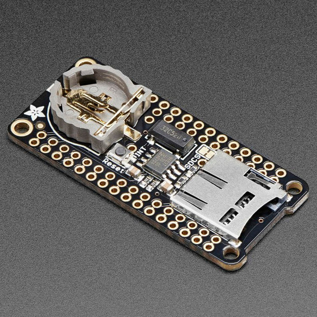
Adafruit Adafruit Adalogger FeatherWing (RTC + SD Add-on)
This FeatherWing will make it easy to add data logging to any Feather Board you might have. You get both an I²C real-time clock (PCF8523) with 32 KHz crystal and battery backup, and a microSD socket that connects to the SPI port pins (+ extra pin for CS). Note: FeatherWing doesn't come with a microSD card. A CR1220 coin cell is required to use the RTC battery-backup capabilities. If you're not using the RTC part of the FeatherWing, a battery is not required. To talk to the microSD card socket Arduino's default SD library is recommended. Some light soldering is required to attach the headers onto the Wing. Pinouts Power pins On the bottom row, the 3.3 V (second from left) and GND (fourth from left) pin are used to power the SD card and RTC (to take a load off the coin cell battery when main power is available) RTC & I²C Pins In the top right SDA (rightmost) and SCL (to the left of SDA) are used to talk to the RTC chip. SCL - I²C clock pin to connect to your microcontroller's I2C clock line. This pin has a 10 kΩ pull-up resistor to 3.3 V SDA - I²C data pin to connect to your microcontroller's I2C data line. This pin has a 10 kΩ pull-up resistor to 3.3 V There's also a breakout for INT which is the output pin from the RTC. It can be used as an interrupt output or it could also be used to generate a square wave. Note that this pin is an open drain - you must enable the internal pull-up on whatever digital pin it is connected to. SD & SPI Pins Starting from the left you've got SPI Clock (SCK) - output from feather to wing SPI Master Out Slave In (MOSI) - output from feather to wing SPI Master In Slave Out (MISO) - input from wing to feather These pins are in the same location on every Feather. They are used for communicating with the SD card. When the SD card is not inserted, these pins are completely free.
-
Elektor Digital Advanced Control Robotics (E-book)
If you enjoy DIY electronics, projects, software and robots, you’ll find this book intellectually stimulating and immediately useful. With the right parts and a little guidance, you can build robot systems that suit your needs more than overpriced commercial systems can. 20 years ago, robots based on simple 8-bit processors and touch sensors were the norm. Now, it’s possible to build multi-core robots that can react to their surroundings with intelligence. Today’s robots combine sensor readings from accelerometers, gyroscopes and computer vision sensors to learn about their environments. They can respond using sophisticated control algorithms and they can process data both locally and in the cloud. This book, which covers the theory and best practices associated with advanced robot technologies, was written to help roboticists, whether amateur hobbyist or professional, take their designs to the next level. As will be seen, building advanced applications does not require extremely costly robot technology. All that is needed is simply the knowledge of which technologies are out there and how best to use each of them. Each chapter in this book will introduce one of these different technologies and discuss how best to use it in a robotics application. On the hardware side, we’ll cover microcontrollers, servos, and sensors, hopefully inspiring you to design your own awe-inspiring, next-generation systems. On the software side, we’ll cover programming languages, debugging, algorithms, and state machines. We’ll focus on the Arduino, the Parallax Propeller, Revolution Education PICAXE and projects I’ve with which I’ve been involved, including the TBot educational robot, the PropScope oscilloscope, the 12Blocks visual programming language, and the ViewPort development environment. In addition, we’ll serve up a comprehensive introduction to a variety of essential topics, including output (e.g. LEDs, servo motors), and communication technologies (e.g. infrared, audio), that you can use to develop systems that interact to stimuli and communicate with humans and other robots. To make these topics as accessible as possible, handy schematics, sample code and practical tips regarding building and debugging have been included. Hanno Sander Christchurch, New Zealand
€ 24,95
Members: € 22,46
-
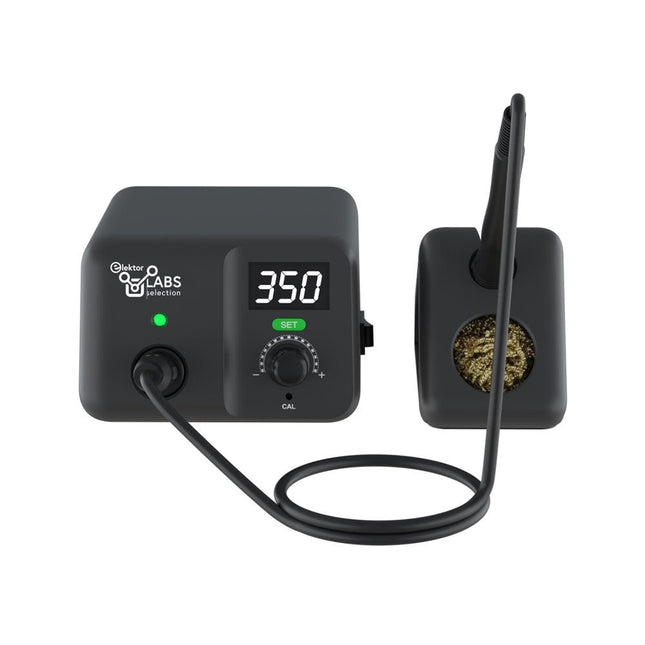
Eleshop AE970D Soldering Station (80 W)
Soldering station for precision soldering with actively heated soldering tip The AE970D soldering iron station is a 80 W high power tool to heat up to solder fastly. Its wide temperature range of 150-550°C (302-1022°F) could meet all your soldering needs. Thanks to its high performance plug-and-play integrated active tip, AE970D can reach melting point within 9 seconds. Patented close-loop automatic constant temperature control technology can ensure its soldering with high stability, excellent performance and precise accuracy. Features 80 W high power to enable fast heating up Wider temperature range of 150-550°C (302-1022°F) to meet all your soldering needs High performance plug-and-play integrated active tip, can reach melting point within 9 seconds Patented close-loop automatic constant temperature control technology to ensure high stability, excellent performance and precise accuracy Specifications Power 80 W Input voltage 110 VAC / 230 VAC Output voltage 25 VAC Temperature range 150-550°C (302-1022°F) Heating element T80 series integrated active heater Temperature stability ±1°C/±1.8°F (when temperature >200°C/400°F) Tip to ground resistance <2 Ω Tip to ground voltage <2 mV Power cord length 1 m Handle cable length 1.2 m Dimensions 148 x 120 x 85 mm Weight (main unit) 1.33 kg Included Main unit Soldering iron incl. soldering tip T80-D12 Iron stand Brass wool Manual
€ 95,00
-

Elektor Digital Analogue Video (E-book)
This book is intended for electronics enthusiasts and professionals alike, who want a much deeper understanding of the incredible technology conquests over the pre-digital decades that created video. It details evolution of analogue video electronics and technology from the first electro-mechanical television, through advancements in Cathode Ray Tubes, transistor circuits and signal processing, up to the latest analogue, colour-rich TV, entertainment devices and calibration equipment. Key technological advances that enabled monochrome video and, eventually, colour are explained. The importance, compromises and techniques of maintaining crucial backward legacy compatibilities are described. The generation, signal processing and playback of analogue video signals in numerous capture, display, recording and playback devices together with operating principles and practices are examined. Technical and, often, political merits and deficiencies of key national and international video standards are highlighted. Several formats are shown to win and ultimately to co-exist. This book begins at fairly basic levels; concepts are introduced with human physiological perceptions of light and colour explained. This leads to the subject matter of luminance and chrominance; their equations and the circuits to process. There is full, detailed analysis of waveform shapes and timings inside video equipment and relevant popular connections e.g. S-video. Several analogue video projects which you can build yourself are also included in this book; with schematics, circuit board layouts and calibration steps to help you obtain the best results. The book makes use of many colour pages where the subject matter demands it (e.g. test cards). If you really want a deeper understanding of analogue video then this book is for you!
€ 24,95
Members: € 22,46
-
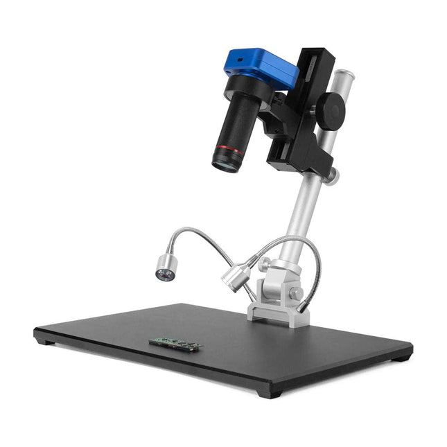
Andonstar Andonstar AD1605 4K HDMI Digital Microscope
The Andonstar AD1605 4K Digital Microscope features a 14 megapixels HD sensor, an oversized metal base and an adjustable bracket. With 4k ultra HD image sensor, you can capture high-quality pictures and record ultra-clear videos. This 4K digital microscope possesses a magnification up to 150X. With a stand size of 37.5 x 25 x 47 cm, it can offer a large working space that is ideal for assembly, inspection, training, real-time viewing, image capture and video documentation. With it, you can check the solder joint of a circuit board, or the minute structure of coin, jewelry, textile, skin, insect, etc. Features 14 MP HD sensor providing clear images of high quality Deep depth of field making images sharp and clear Oversized metal base providing large working space Wide focus range from 5 to 29 cm Adjustable metal bracket for easy adjustment of magnification and object distance Image capture & video record function for convenient documentation of work UV Filter to protect the lens from the oil, heat, dirt or dust during soldering or repair IR remote control for easy operation and avoid the shake of the microscope with the button playing Memory card with up to 32 GB storage (not included in the package) Applications Phone repair PCB checking Plants & insects Arts & crafts/miniature Printings/textile Assembling line Antique authentication Jewelry appraisal Watch repair DIY Specifications Image sensor 14 MP Video output 3840x2160 (30fps)2560x1440 (24fps)1920x1080 (60fps/30fps) Video format MP4 Magnification Up to 150 times (29 inch HDMI monitor) Photo resolution Max. 12 MP (4032x3024) Photo format JPG Focus range 5-29 cm Frame Rate Max. 60fps Video interface HDMI Storage microSD card (up to 32 GB) PC support No Power source 5 V DC Light source 2 LEDs with the stand Stand size 37.5 x 25 x 47 cm Weight 5.5 kg Included 1x Andonstar AD1605 Digital Microscope 1x Metal stand 1x UV filter 1x IR remote 1x Switch cable 1x Power adapter 1x User manual
€ 349,00
-
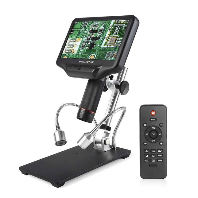
Andonstar Andonstar AD407 7" HDMI Digital Microscope
Examine your circuits with high precision and solder even the smallest SMDs and elements without any hassle. Features Multifunctional HDMI Digital Microscope features Full HD, comfortable headroom, improved ergonomy, multiple output signals with different resolutions. Tilt angle of the wide LCD monitor is adjustable. Comes with remote control. Can be used as stand-alone. Specifications Screen size 7 inch (17.8 cm) Image sensor 4 MP Video output UHD 2880x2160 (24fps)FHD 1920x1080 (60fps/30fps)HD 1280x720 (120fps) Video format MP4 Magnification Up to 270 times (27 inch HDMI monitor) Photo resolution Max. 12 MP (4032x3024) Photo format JPG Focus range Min. 5 cm Frame rate Max. 120fps (under 600 Lux Brightness & HDP120) Video interface HDMI Storage microSD card (up to 32 GB) Power source 5 V DC Light source 2 LEDs with the stand Stand size 20 x 12 x 19 cm Included 1x Andonstar AD407 Digital Microscope 1x Metal stand with 2 LEDs 1x Optical bracket 1x UV filter 1x IR remote 1x Switch cable 1x Power adapter 1x HDMI cable 2x Screws 1x Screwdriver 1x User manual Downloads Manual Model Comparison AD407 AD407 Pro AD409 AD409 Pro-ES Screen size 7 inch (17.8 cm) 7 inch (17.8 cm) 10.1 inch (25.7 cm) 10.1 inch (25.7 cm) Image sensor 4 MP 4 MP 4 MP 4 MP Video output 2160p 2160p 2160p 2160p Interfaces HDMI HDMI USB, HDMI, WiFi USB, HDMI, WiFi Video format MP4 MP4 MP4 MP4 Magnification Up to 270x Up to 270x Up to 300x Up to 300x Photo resolution Max. 4032x3024 Max. 4032x3024 Max. 4032x3024 Max. 4032x3024 Photo format JPG JPG JPG JPG Focus distance Min. 5 cm Min. 5 cm Min. 5 cm Min. 5 cm Frame rate Max. 120f/s Max. 120f/s Max. 120f/s Max. 120f/s Storage microSD card microSD card microSD card microSD card PC support No No Windows Windows Mobile connection No No WiFi + Measurement WiFi + Measurement Power source 5 V DC 5 V DC 5 V DC 5 V DC Light source 2 LEDs with the stand 2 LEDs with the stand 2 LEDs with the stand 2 LEDs with the stand Endoscope No No No Yes Stand size 20 x 12 x 19 cm 20 x 18 x 32 cm 18 x 20 x 30 cm 18 x 20 x 32 cm Weight 1.6 kg 2.1 kg 2.2 kg 2.5 kg
€ 185,13
-
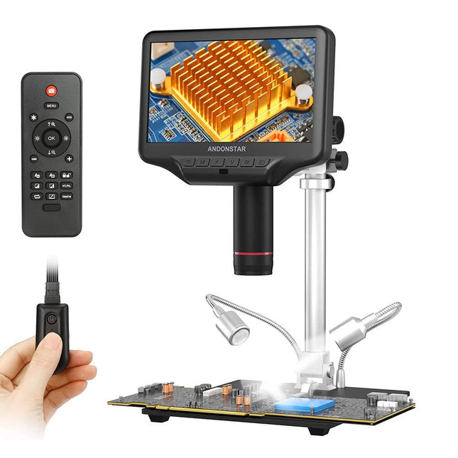
Andonstar Andonstar AD407 Pro 7" HDMI Digital Microscope
The Andonstar AD407 Pro microscope is suitable for various applications such as soldering SMDs or repair work. The microscope has a large adjustable 7" LCD display and comes with a remote. Compared to AD407, AD407 Pro offers an extra-high stand, which makes soldering of components even easier. Specifications Screen size 7 inch (17.8 cm) Image sensor 4 MP Video output UHD 2880x2160 (24fps)FHD 1920x1080 (60fps/30fps)HD 1280x720 (120fps) Video format MP4 Magnification Up to 270 times (27 inch HDMI monitor) Photo resolution Max. 12 MP (4032x3024) Photo format JPG Focus range Min. 5 cm Frame Rate Max. 120fps Video interface HDMI Storage microSD card (up to 64 GB) Power source 5 V DC Light source 2 LEDs with the stand Stand size 20 x 18 x 32 cm Included 1x Andonstar AD407 Pro Digital Microscope 1x Metal stand with 2 LEDs 1x UV filter (already assembled in the lens) 1x IR remote 1x Switch cable 1x Power adapter 1x Wrench 2x Metal clips 1x HDMI cable 1x Manual Downloads Manual Model Comparison AD407 AD407 Pro AD409 AD409 Pro-ES Screen size 7 inch (17.8 cm) 7 inch (17.8 cm) 10.1 inch (25.7 cm) 10.1 inch (25.7 cm) Image sensor 4 MP 4 MP 4 MP 4 MP Video output 2160p 2160p 2160p 2160p Interfaces HDMI HDMI USB, HDMI, WiFi USB, HDMI, WiFi Video format MP4 MP4 MP4 MP4 Magnification Up to 270x Up to 270x Up to 300x Up to 300x Photo resolution Max. 4032x3024 Max. 4032x3024 Max. 4032x3024 Max. 4032x3024 Photo format JPG JPG JPG JPG Focus distance Min. 5 cm Min. 5 cm Min. 5 cm Min. 5 cm Frame rate Max. 120f/s Max. 120f/s Max. 120f/s Max. 120f/s Storage microSD card microSD card microSD card microSD card PC support No No Windows Windows Mobile connection No No WiFi + Measurement WiFi + Measurement Power source 5 V DC 5 V DC 5 V DC 5 V DC Light source 2 LEDs with the stand 2 LEDs with the stand 2 LEDs with the stand 2 LEDs with the stand Endoscope No No No Yes Stand size 20 x 12 x 19 cm 20 x 18 x 32 cm 18 x 20 x 30 cm 18 x 20 x 32 cm Weight 1.6 kg 2.1 kg 2.2 kg 2.5 kg
€ 226,27
-
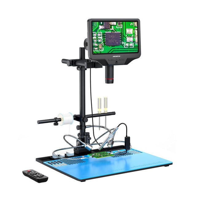
Andonstar Andonstar AD409 Max-ES 10.1" HDMI Digital Microscope (incl. Endoscope)
The Andonstar AD409 Max-ES boosts a high-quality metal lens and a unique UV filter design. Crafted from top-tier industrial-grade materials, it delivers unmatched precision and durability, ensuring a reliable product experience. The UV filter positioned in front of the metal lens blocks soldering heat, smoke, and dust, safeguarding the lens and making it perfect for soldering and maintenance professionals. The AD409 Max-ES features an oversized Max station (46 x 37 x 47.5 cm) and an advanced tool set, expanding the soldering station area by 370%. This upgrade meets the demands of professional soldering tasks and provides ample workspace for larger projects. The easy-to-use tool holder keeps tools within reach, ensuring they are always accessible. Additionally, the soldering helping hands with rotatable clamps simplify soldering and repair tasks, enhancing efficiency and convenience. The endoscope offers an all-around 360° view. This allows for clear observation of components from all sides and inside pipes, eliminating blind spots and ensuring thorough inspections. Features High-quality Metal Lens and Unique UV Filter Design New Max station Easy-to-use Tool Holder and Soldering Helping Hands Microscope with Endoscope All-around View 360° Professional HDMI Digital Microscope supports Multiple Output Methods 8 Levels adjustable LEDs Convenient Wireless Remote Control Specifications Screen size 10.1 inch (1280x800) Image sensor 4 MP Video output UHD 2880x2160 (24fps)FHD 1920x1080 (60fps/30fps)HD 1280x720 (120fps) Video format MP4 Magnification Up to 300 times (27 inch HDMI monitor) Photo resolution Max. 24 MP (5600x4200) Photo format JPG Focus range Min. 5 cm Frame Rate Max. 120fps Video interface HDMI Storage microSD card (up to 64 GB) PC support Windows, PC software with measurement Mobile phone, tablet terminal support Support WiFi connection and measurement Power source 5 V DC Light source 2 LEDs with the stand Endoscope Yes Stand size 46 x 37 x 47.5 cm (18.1 x 14.6 x 18.7") Included 1x Andonstar AD409 Max-ES Digital Microscope 1x Endoscope 1x Stand with 2 LEDs 1x UV filter (already assembled in the lens) 1x Soldering mat 1x Beam 1x Column 1x Tool holder 1x Soldering Helping Hands 1x Power adapter 1x Power cable 1x HDMI cable 1x USB cable 1x IR remote 1x Manual Downloads Manual Software
€ 399,00€ 349,00
Best Price
-
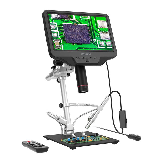
Andonstar Andonstar AD409 Pro-ES 10.1" HDMI Digital Microscope (incl. Endoscope)
The Andonstar AD409 Pro-ES is a digital microscope with an extra-high stand that is also equipped with an endoscope. The microscope allows clear observation of the sides of components, the inside of pipes, etc., enabling 360° observation without dead angles. The microscope also has a remote control that allows you to easily switch between the following image modes: two-lens, microscope and endoscope. Features High-quality metal lens and focusing barrel Professional HDMI digital microscope supports multiple output methods Soldering Microscope with Pro Metal Stand Unique UV filter design 8 Levels adjustable LED Lights Convenient Wireless Remote Control Professional Measurement Software Specifications Screen size 10.1 inch (25.7 cm) Image sensor 4 MP Video output UHD 2880x2160 (24fps)FHD 1920x1080 (60fps/30fps)HD 1280x720 (120fps) Video format MP4 Magnification Up to 300 times (27 inch HDMI monitor) Photo resolution Max. 12 MP (4032x3024) Photo format JPG Focus range Min. 5 cm Frame Rate Max. 120fps Video interface HDMI Storage microSD card (up to 64 GB) PC support Windows, PC software with measurement Mobile phone, tablet terminal support Support WiFi connection and measurement Power source 5 V DC Light source 2 LEDs with the stand Endoscope Yes Stand size 18 x 20 x 32 cm Included 1x Andonstar AD409 Pro-ES Digital Microscope 1x Endoscope 1x Metal stand with 2 LEDs 1x UV filter (already assembled in the lens) 1x IR remote 1x Switch cable 1x Power adapter 1x Wrench 2x Metal clips 1x HDMI cable 1x User manual Downloads Manual Software
€ 349,00€ 299,00
Best Price
-

Andonstar Andonstar ADSM302 5" HDMI Digital Microscope
The Andonstar ADSM302 is a versatile digital microscope with an integrated 5-inch LCD display and HDMI output for crystal-clear views in Full HD (1080p). With a 3-megapixel sensor, up to ~560x magnification, and two adjustable LED lights, it reveals the finest details – ideal for PCB inspections, soldering work, jewelry or insect analysis. Features 5" adjustable LCD monitor with adjustable tilt angle High resolution video & photo capture Wide table with comfortable headroom Heavy-weight stable metal stand Tall lifting stand (26 cm) Smooth adjustment wheels for focus and height Buttons on the monitor + remote control AV, USB, HDMI outputs SD card storage <32 GB Specifications Image sensor 3 Megapixels HD Sensor Video output 1080p Full HD (via HDMI)720p (via PC) Video format Real time play via HDMI w/o recordingMJPEG recording via PC/Mac Software Magnification Up to 560 times (HDMI monitor 22") Photo resolution 12M (see pixel formats in following table) Photo format JPEG Focus range 5 to 22 cm Frame rate Up to 30 f/s under 600 Lux Brightness Video-output interface HDMI/AV Storage microSD card, up to 32 GB PC support Windows XP/7/8/10PC software with measurementMacOS successfully tested under OSX with OBSsee video below Power source 5 V DC Light source 2x LED with the stand Screen size 5 inch (12.7 cm) Stand size 20 x 12 x 26.5 cm Resolution Captured Photos 4032 x 3024 3648 x 2736 3264 x 2448 2592 x 1944 2048 x 1536 640 x 480 1920 x 1080 1280 x 960 1280 x 720* Videos 1920 x 1080 640 x 480* * (USB with software) Included 1x Andonstar ADSM302 digital microscope 1x Metal stand with 2 LEDs 1x USB cable 1x HDMI cable 1x Adapter 1x AI remote 1x Instructions Downloads Manual Software
€ 199,00
-
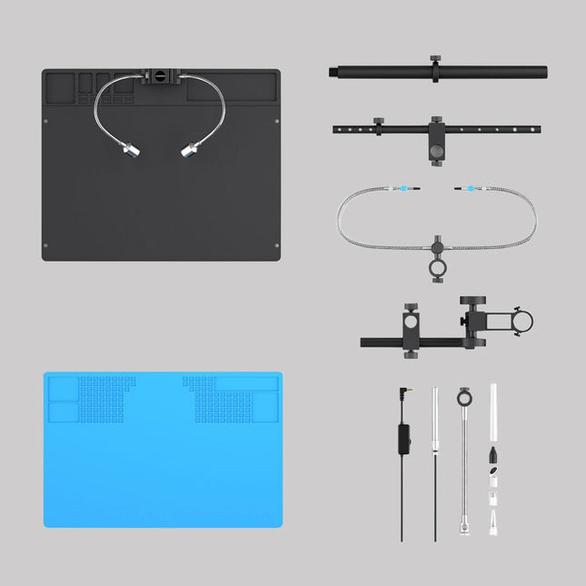
Andonstar Andonstar Max Station Upgrade Set for AD409 Models
Upgrade your Andonstar AD409, AD409 Pro, or AD409 Pro-ES to the Max model with this enhancement kit. The newly designed, oversized Max station provides ample workspace, making it perfect for larger projects and ideal for professional soldering tasks. Included 1x Stand with 2 LEDs 1x Repair mat 1x Beam 1x Column 1x Tool holder 1x Soldering Helping Hands
€ 60,00


