
Search results for "4 OR digit OR in OR 12 OR nixie OR clock OR kit"
-
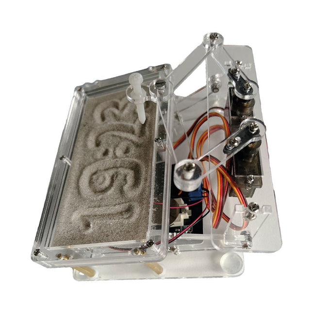
Elektor Labs Elektor Sand Clock for Raspberry Pi Pico
Raspberry Pi-based Eye Catcher A standard sand clock just shows how time passes. In contrast, this Raspberry Pi Pico-controlled sand clock shows the exact time by “engraving” the four digits for hour and minute into the layer of sand. After an adjustable time the sand is flattened out by two vibration motors and everything begins all over again. At the heart of the sand clock are two servo motors driving a writing pen through a pantograph mechanism. A third servo motor lifts the pen up and down. The sand container is equipped with two vibration motors to flatten the sand. The electronic part of the sand clock consists of a Raspberry Pi Pico and an RTC/driver board with a real-time clock, plus driver circuits for the servo motors. A detailed construction manual is available for downloading. Features Dimensions: 135 x 110 x 80 mm Build time: approx. 1.5 to 2 hours Included 3x Precut acrylic sheets with all mechanical parts 3x Mini servo motors 2x Vibration motors 1x Raspberry Pi Pico 1x RTC/driver board with assembled parts Nuts, bolts, spacers, and wires for the assembly Fine-grained white sand
€ 49,95€ 39,95Best Price
-
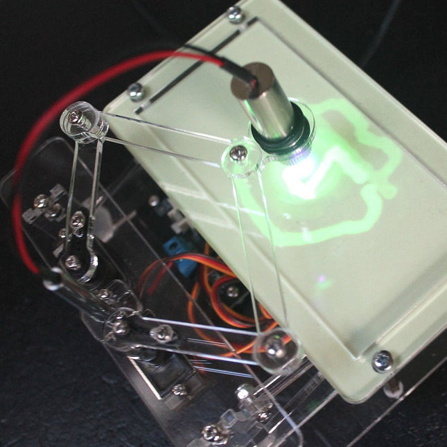
Elektor Labs Elektor Laser Head Upgrade for Sand Clock
The Elektor Laser Head transforms the Elektor Sand Clock into a clock that writes the time on glow-in-the-dark film instead of sand. In addition to displaying the time, it can also be used to create ephemeral drawings. The 5 mW laser pointer, with a wavelength of 405 nm, produces bright green drawings on the glow-in-the-dark film. For best results, use the kit in a dimly lit room. Warning: Never look directly into the laser beam! The kit includes all the necessary components, but soldering three wires is required. Note: This kit is also compatible with the original Arduino-based Sand Clock from 2017. For more details, see Elektor Magazine 1-2/2017 and Elektor Magazine 1-2/2018.
€ 34,95€ 24,95Best Price
-
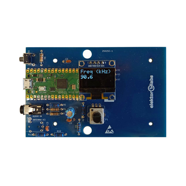
Elektor Labs Elektor AM Transmitter Kit
Build Your Own Vintage Radio Broadcaster The Elektor AM Transmitter Kit allows streaming audio to vintage AM radio receivers. Based on a Raspberry Pi Pico microcontroller module, the AM Transmitter can transmit on 32 frequencies in the AM band, from 500 kHz up to 1.6 MHz in 32 steps of approx. 35 kHz. The frequency is selected with a potentiometer and shown on a 0.96" OLED display. A pushbutton allows toggles the transmitting mode between On and Off. The range of the transmitter depends on the antenna. The onboard antenna provides a range of a few centimeters, requiring the AM Transmitter to be placed close to or inside the radio. An external loop antenna (not included) can be connected to increase the range. The Elektor AM Transmitter Kit comes as a kit of parts that you must solder to the board yourself. Features The board is compatible with a Hammond 1593N enclosure (not included).A 5 VDC power supply with micro-USB connector (e.g., an old phone charger) is needed to power the kit (not included). Current consumption is 100 mA. The Arduino software (requiring Earle Philhower’s RP2040 Boards Package) for the Elektor AM Transmitter Kit plus more information is available at the Elektor Labs page of this project. Component List Resistors R1, R4 = 100 Ω R2, R3, R8 = 10 kΩ R5, R6, R9, R10, R11 = 1 kΩ R7 = optional (not included) P1 = potentiometer 100 kΩ, linear Capacitors C1 = 22 µF 16V C2, C4 = 10 nF C3 = 150 pF Miscellaneous K1 = 4×1 pin socket K2, K3 = 3.5 mm socket Raspberry Pi Pico pushbutton, angle mount 0.96" monochrome I²C OLED display PCB 150292-1
€ 34,95€ 29,95Best Price
-

Elektor Labs Elektor Sand Clock for Raspberry Pi Pico (incl. Laser Head Upgrade)
This bundle contains the popular Elektor Sand Clock for Raspberry Pi Pico and the new Elektor Laser Head Upgrade, offering even more options for displaying the time. Not only can you "engrave" the current time in sand, you can now alternatively write it on a glow-in-the-dark foil or create green drawings. Contents of the bundle Elektor Sand Clock for Raspberry Pi Pico (normal price: €50) Elektor Laser Head Upgrade for Sand Clock (normal price: €35) Elektor Sand Clock for Raspberry Pi (Raspberry Pi-based Eye Catcher) A standard sand clock just shows how time passes. In contrast, this Raspberry Pi Pico-controlled sand clock shows the exact time by "engraving" the four digits for hour and minute into the layer of sand. After an adjustable time the sand is flattened out by two vibration motors and everything begins all over again. At the heart of the sand clock are two servo motors driving a writing pen through a pantograph mechanism. A third servo motor lifts the pen up and down. The sand container is equipped with two vibration motors to flatten the sand. The electronic part of the sand clock consists of a Raspberry Pi Pico and an RTC/driver board with a real-time clock, plus driver circuits for the servo motors. A detailed construction manual is available for downloading. Features Dimensions: 135 x 110 x 80 mm Build time: approx. 1.5 to 2 hours Included 3x Precut acrylic sheets with all mechanical parts 3x Mini servo motors 2x Vibration motors 1x Raspberry Pi Pico 1x RTC/driver board with assembled parts Nuts, bolts, spacers, and wires for the assembly Fine-grained white sand Elektor Laser Head Upgrade for Sand Clock The new Elektor Laser Head transforms the Sand Clock into a clock that writes the time on glow-in-the-dark film instead of sand. In addition to displaying the time, it can also be used to create ephemeral drawings. The 5 mW laser pointer, with a wavelength of 405 nm, produces bright green drawings on the glow-in-the-dark film. For best results, use the kit in a dimly lit room. Warning: Never look directly into the laser beam! The kit includes all the necessary components, but soldering three wires is required. Note: This kit is also compatible with the original Arduino-based Sand Clock from 2017. For more details, see Elektor Magazine 1-2/2017 and Elektor Magazine 1-2/2018.
€ 84,95€ 69,95Best Price
-
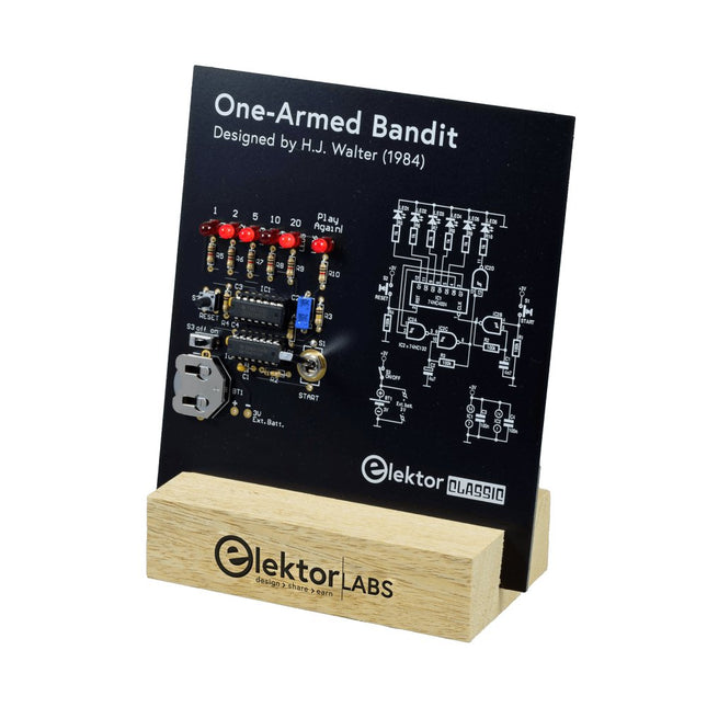
Elektor Labs Elektor One-armed Bandit
Pull Down Lever For Highest Score! This Elektor Circuit Classic from 1984 shows a playful application of CMOS 400x series logic ICs in combination with LEDs, a highly popular combination at the time. The project imitates a spinning-digit type slot machine. The Game To play the game, first agree on the number of rounds. Player 1 actuates the switch lever as long as desired and releases it. The LEDs then show the score which is the sum of the 50-20-10-5 digits lit up. If the Play Again! LED lights, Player 1 has another, “free” round. If not, it’s Player 2’s turn. The players keep tab of their scores, and the highest score wins. Features LEDs Indicate Score Multi-Player and Play Again! Elektor Heritage Circuit Symbols Tried & Tested by Elektor Labs Educational & Geeky Project Through-Hole Parts Only Included Printed Circuit Board All Components Wooden Stand Bill of Materials Resistors (5%, 250 mW) R1,R2,R3,R4 = 100kΩ R5,R6,R7,R8,R9,R10 = 1kΩ Capacitors C1 = 4.7nF, 10%, 50V, 5mm C2 = 4.7μF, 10%, 63V, axial C3,C4 = 100nF, 10 %, 50V, ceramic X7R, 5mm Semiconductors LED1-LED6 = red, 5mm (T1 3/4) IC1 = 74HC4024 IC2 = 74HC132 Miscellaneous S1 = switch, toggle, 21mm lever, SPDT, momentary S2 = switch, tactile, 24V, 50mA, 6x6mm S3 = switch, slide, SPDT IC1,IC2 = IC socket, DIP14 BT1 = PCB-mount CR2032 battery retainer clip Desktop Stand PCB 230098-1 Not included: BT1 = CR2032 coin cell battery
€ 39,95€ 15,98Best Price
-
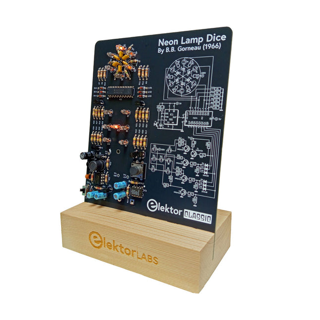
Elektor Labs Elektor Neon Lamp Dice
A Retro Roll with a Neon Soul LED-based dice are common, but their light is cold. Not so for this electronic neon dice, which displays its value with the warm glow of neon lamps. It is perfect for playing games on cold, dark winter evenings. The pips of the dice are neon lamps and the random number generator has six neon lamps to show that it is working. Even though the dice has an on-board 100-V power supply, it is completely safe. As with all Elektor Classic products, the dice too has its circuit diagram printed on the front while an explanation of how the circuit works can be found on the rear side. The Neon Lamp Dice comes as a kit of easy-to-solder through-hole parts. The power supply is a 9-V battery (not included). Features Warm Vintage Glow Elektor Heritage Circuit Symbols Tried & Tested by Elektor Labs Educational & Geeky Project Through-Hole Parts Only Included Printed Circuit Board All Components Wooden Stand Required 9 V battery Component List Resistors (THT, 150 V, 0.25 W) R1, R2, R3, R4, R5, R6, R14 = 1 MΩ R7, R8, R9, R10, R11, R12 = 18 kΩ R13, R15, R16, R17, R18, R21, R23, R24, R25, R26, R28, R30, R33 = 100 kΩ R32, R34 = 1.2 kΩ R19, R20, R22, R27, R29 = 4.7 kΩ R31 = 1 Ω Capacitors C1, C2, C3, C4, C5, C6 = 470 nF, 50 V, 5 mm pitch C7, C9, C11, C12 = 1 µF, 16 V, 2 mm pitch C8 = 470 pF, 50 V, 5 mm pitch C10 = 1 µF, 250 V, 2.5 mm pitch Inductors L1 = 470 µH Semiconductors D1, D2, D3, D4, D5, D6, D7 = 1N4148 D8 = STPS1150 IC1 = NE555 IC2 = 74HC374 IC3 = MC34063 IC4 = 78L05 T1, T2, T3, T4, T5 = MPSA42 T6 = STQ2LN60K3-AP Miscellaneous K1 = PP3 9 V battery holder NE1, NE2, NE3, NE4, NE5, NE6, NE7, NE8, NE9, NE10, NE11, NE12, NE13 = neon light S2 = Miniature slide switch S1 = Pushbutton (12 x 12 mm)
-

Generic LC Meter Kit
This LC meter kit is an easy-to-build, educational, and entertaining DIY project for measuring the inductance (L) of coils and inductors, the capacitance (C) of capacitors, other passive components and the frequency of signals. Specifications Power supply USB DC 5 V Capacitance measurement range of small non-polarized capacitors 1 pF~2200 pF Capacitance measurement range of electrolytic capacitors 1 µF~12000 µF Inductance measurement range 1 µH~1 H Frequency measurement range 20 Hz~400 kHz Dimensions (PCB) 91 x 80 mm Dimensions (Shell) 106 x 91 x 28 mm Included Doubled-sided PCB All required components incl. LCD display Six pre-cut transparent acrylic plates Screws and nuts
-
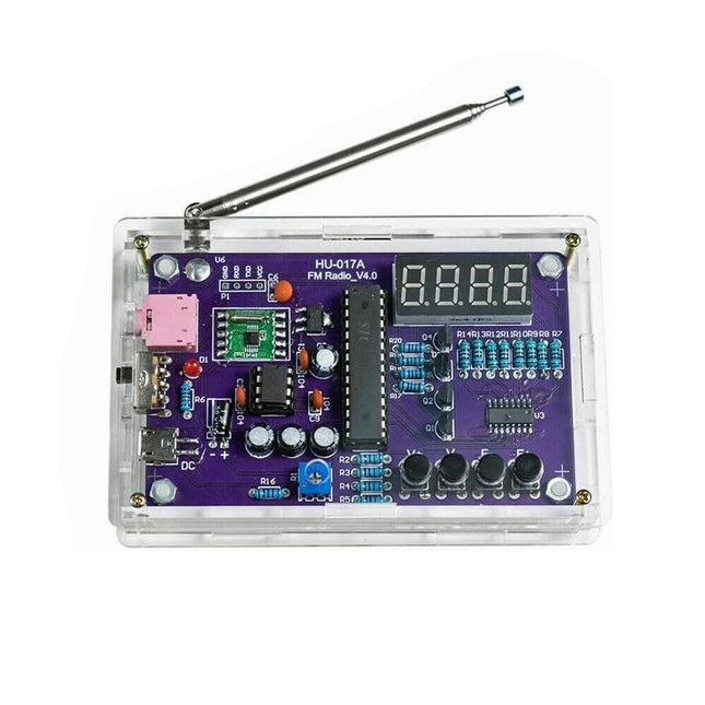
Generic FM Radio Kit
This DIY kit (HU-017A) is a wireless FM radio receiver with a 4-digit 7-segment display. It operates within the global FM receiving frequency band of 87.0-108.0 MHz, making it suitable for use in any country or region. The kit offers two power supply modes, allowing you to use it both at home and outdoors. This DIY electronic product will help you understand circuits and improve your soldering skills. Features 87.0-108.0 MHz FM Radio: Built-in RDA5807 FM data processor with a standard FM receiving frequency band. The FM frequency can be adjusted using the F+ and F- buttons. Adjustable Volume: Two volume adjustment methods – button and potentiometer. There are 15 volume levels. Active & Passive Audio Output: The kit has a built-in 0.5 W power amplifier to drive 8 Ω speakers directly. It also outputs audio signals to headsets or loudspeakers with AUX interfaces, allowing personal listening and sharing of FM audio. Configured with a 25 cm dedicated FM antenna and a (red) 4-digit 7-segment display for real-time display of FM radio frequency. The transparent acrylic shell protects the internal circuit board. It supports dual power supply methods – 5 V USB and 2x 1.5 V (AA) batteries. DIY Hand Soldering: The kit comes with various components that need to be installed manually. It helps exercise and improve soldering skills, making it suitable for electronics hobbyists, beginners, and educational purposes. Specifications Operating voltage DC 3 V/5 V Output impedance 8 Ω Output power 0.5 W Output channel Mono Receiver frequency 87.0 MHz~108.0 MHz Frequency accuracy 0.1 MHz Operating temperature −40°C to +85°C Operating humidity 5% to 95% RH Dimensions 107 x 70 x 23 mm IMPORTANT: Remove the batteries when powering the radio over to USB. Included 1x PCB 1x RDA5807M FM Receiver 1x STC15W404AS MCU 1x IC Socket 1x 74HC595D Register 1x TDA2822M Amplifier 1x IC Socket 1x AMS1117-3.3 V Voltage Converter 18x Metal Film Resistor 1x Potentiometer 4x Ceramic Capacitor 5x Electrolytic Capacitor 4x S8550 Transistor 1x Red LED 1x 4-digit 7-segment Display 1x Toggle Switch 1x SMD Micro USB Socket 1x Radio Antenna 1x AUX Audio Socket 4x Black Button 4x Button Cap 1x 0.5 W/8 Ω Speaker 1x Red/Black Wire 2x Double-sided adhesive 1x AA Battery Box 1x USB cable 6x Acrylic Board 4x Nylon Column Screw 4x M3 Screw 4x M3 Nut 4x M2x22 mm Screw 1x M2x6 mm Screw 5x M2 Nut


-

, by Udo Bormann Top 4 Elektor Electronics Project Kits for Learning and Skill Development
Discover four of Elektor’s most exciting electronics kits — from IoT and Arduino to retro logic and motion control. Whether you're just starting out or...
-
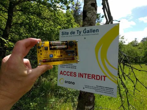
, by Clemens Valens Review: Detect Radiation with the MightyOhm Geiger Counter Kit
The MightyOhm Geiger Counter is a device for detecting beta and gamma radiation levels. Because radiation is so harmful, you may want to keep an...
