Search results for "arduino ch"
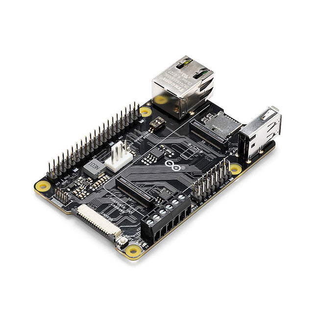
Arduino Arduino Portenta HAT Carrier
Portenta HAT Carrier is a reliable and robust carrier that transforms Portenta X8 into an industrial single board computer compatible with Raspberry Pi HATs and cameras. It is ideal for multiple industrial applications such as building automation and machine monitoring.Compatible also with Portenta H7 and Portenta C33, Portenta HAT Carrier provides easy access to multiple peripherals – including CAN, Ethernet, microSD and USB – and further extends any Portenta application.It is great for prototyping and ready for scaling up, it extends the features found on a typical Raspberry Pi Model B. Debug quickly with dedicated JTAG pins and keeps heat manageable under intense workloads with a PWM fan connector. Control actuators or read analog sensors via the additional 16x analog I/Os. Add industrial machine vision solutions to any project by leveraging the onboard camera connector.Features Add Raspberry Pi HATs to your Portenta projects Quickly access CAN, USB, and Ethernet peripherals Leverage onboard MicroSD card to log data Enjoy simple debugging through the onboard JTAG pins Easily control actuators and read sensors via 16x analog I/Os Leveraging the onboard camera connector for machine vision Portenta takes you from prototype to high-performancePortenta HAT Carrier offers you a frictionless Linux prototyping experience and unlocks the ability for integrated real-time MCU solutions. Portenta HAT Carrier extends Portenta SOMs for faster, easier and more efficient testing for your ideas while also ensuring the capabilities and industrial-grade performances the Portenta range is known for.Extend the Raspberry Pi ecosystem for commercial applicationsCombine the ease of use, accessibility and incredible support from both the Arduino and Raspberry Pi communities for your next project with the carrier designed to combine and extend MPU and MCU applications for the development of advanced commercial solutions.Specifications Connectors High-density connectors compatible with Portenta products 1x USB-A female connector 1x Gigabit Ethernet connector (RJ45) 1x CAN FD with onboard transceiver 1x MIPI Camera connector 1x MicroSD card slot 1x PWM fan connector 40-pin header connector allowing compatibility with Raspberry Pi HATs 16-pin analog header connectors, including: 8x analog inputs 1x GPIO 1xUART without flow control 2x PWM pins 1x LICELL pin for Portenta's RTC power Interfaces CAN FD UART SAI ANALOG GPIO SPI I²C I²S PWM Debugging Onboard 10x pin 1.27 mm JTAG connector Power From onboard screw terminal block allowing: 7-32 V power supply, powering both the carrier and the connected Portenta 5 V power supply From USB-C on Portenta From 5 V on 40-pin header connector Dimensions 85 x 56 mm Downloads Datasheet Schematics
€ 54,95
Members € 49,46
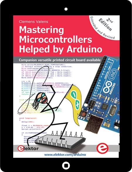
Elektor Digital Mastering Microcontrollers Helped by Arduino Chapter 11 (E-book)
Extra chapter of the second and revised edition of Mastering Microcontrollers Helped by Arduino (PDF) For those of you who purchased the first edition of Mastering Microcontrollers Helped by Arduino, the extra chapter of the second and revised edition of this book is also available as a PDF file. For this second edition, the author has designed a versatile printed circuit board that can be stacked on an Arduino board. The assembly can be used not only to try out many of the projects presented in this book but also allows for new exercises that in turn provide the opportunity to discover new techniques. Also available is a kit of parts including the PCB and all components. With this kit you can build most of the circuits described in the book and more.
€ 5,50
Members € 4,40
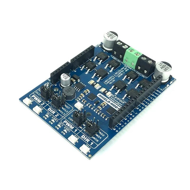
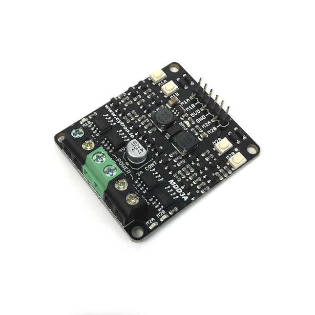
Cytron Cytron 10Amp 7-30 V DC Motor Driver Shield for Arduino (2 Channels)
You can control the motor driver with PWM and DIR inputs. The Arduino pins for these inputs are configurable via jumpers. If the specified pins on Arduino are already used up by other application/shield, you can select another pin easily with the jumper. There is also a possibility to quickly and conveniently test the functionality of the motor driver with the onboard test buttons and output LEDs. Buck regulator which produces 5 V output is also available to power the Arduino mainboard, which eliminates the need of extra power supply for the Arduino mainboard. The board also offers various protection features. Overcurrent protection prevents the motor driver from damage when the motor stalls or an oversized motor is hooked up. When the motor is trying to draw current more than what the motor driver can support, the motor current will be limited at the maximum threshold. Assisted by temperature protection, the maximum current limiting threshold is determined by the board temperature. The higher the board temperature, the lower the current limiting threshold. As a result, the motor driver delivers its full potential depending on the current conditions without damaging any MOSFETs. Features Shield for Arduino form factor Bidirectional control for two brushed DC motors Control one unipolar/bipolar stepper motor Operating Voltage: DC 7 V to 30 V Maximum Motor Current: 10 A continuous, 30 A peak Buck regulator to produce 5 V output (500 mA max) Buttons for quick testing LEDs for motor output state Selectable Arduino pins for PWM/DIR inputs. PWM/DIR inputs compatible with 1.8 V, 3.3 V and 5 V logic PWM frequency up to 20 kHz (Output frequency is same as input frequency). Overcurrent protection with active current limiting Temperature protection Undervoltage shutdown Possible applications Mobile Robot Automated Guided Vehicle (AGV) Solar Tracker Game Simulator Automation Machine Downloads Datasheet Sample Code 3D CAD Files Packing List 1x 10Amps 7V-30V DC Motor Driver Shield for Arduino (2 Channels) MDD010
€ 29,95
Members € 26,96

Elektor Bundles Bundle: Logic Analyzers in Practice (Book) + USB Logic Analyzer (8-ch, 24 MHz)
PC USB Logic Analyzers with Arduino, Raspberry Pi, and Co. Step-by-step instructions guide you through the analysis of modern protocols such as I²C, SPI, UART, RS-232, NeoPixel, WS28xx, HD44780 and 1-Wire protocols. With the help of numerous experimental circuits based on the Raspberry Pi Pico, Arduino Uno and the Bus Pirate, you will learn the practical application of popular USB logic analyzers. All the experimental circuits presented in this book have been fully tested and are fully functional. The necessary program listings are included – no special programming or electronics knowledge is required for these circuits. The programming languages used are MicroPython and C along with the development environments Thonny and Arduino IDE. This book uses several models of flexible and widely available USB logic analyzers and shows the strengths and weaknesses of each price range. You will learn about the criteria that matter for your work and be able to find the right device for you. Whether Arduino, Raspberry Pi or Raspberry Pi Pico, the example circuits shown allow you to get started quickly with protocol analysis and can also serve as a basis for your own experiments. After reading this book, you will be familiar with all the important terms and contexts, conduct your own experiments, analyze protocols independently, culminating in a comprehensive knowledge set of digital signals and protocols. USB Logic Analyzer (8-ch, 24 MHz) This USB Logic Analyzer is an 8-channel logic analyzer with each input dual purposed for analog data recording. It is perfect for debugging and analyzing signals like I²C, UART, SPI, CAN and 1-Wire. It operates by sampling a digital input connected to a device under test (DUT) at a high sample rate. The connection to the PC is via USB. Specifications Channels 8 digital channels Maximum sampling rate 24 MHz Maximum input voltage 0 V ~ 5 V Operating temperature 0°C ~ 70°C Input impedance 1 MΩ || 10 pF Supported protocols I²C, SPI, UART, CAN, 1-Wire, etc. PC connection USB Dimensions 55 x 28 x 14 mm Downloads Software This bundle contains: New book 'Logic Analyzers in Practice' (normal price: €29.95) USB Logic Analyzer (8-ch, 24 MHz) (normal price: €12.95) USB Cable Jumper Wire Ribbon Cable
€ 42,95€ 34,95
Members identical
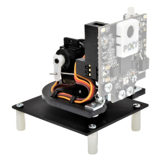
Charmed Labs Pixy2 CMUcam Pan/Tilt Kit
This is a kit for a pan-tilt mechanism explicitly designed for Pixy2. After assembling the kit and connecting it to Pixy2, you'll be able to follow colored objects using the Pan/Tilt demo. It includes two laser-cut plastic pieces for the base, two different servos for the pan and tilt axes, and all the mounting hardware and cable ties you will need to assemble. Features The pan-tilt mechanism for Pixy2 is redesigned, making it smaller and faster than the pan-tilt for the original Pixy. All necessary hardware is included. The pan-tilt base is attached directly to an Arduino with Arduino-compatible hole-pattern and includes stand-offs and fasteners. Several pan-tilt demos are provided that can run using either Arduino, Raspberry Pi or stand-alone (no controller). Complete assembly instructions
€ 39,95
Members € 35,96
Cytron Cytron 3Amp 4-16 V DC Motor Driver (2 Channels)
Features: Supports motor voltage from 4 V to 16 V DC Bidirectional control for two brushed DC motor. Control one unipolar or one bipolar stepper motor. Maximum Motor Current: 3A continuous, 5A peak LEDs for motor output state. Buttons for quick testing. Compatible with Arduino and Raspberry Pi PWM frequency up to 20kHz Reverse polarity protection Here you can find the product's Datasheet. Check out the sample code provided by Cytron here.
€ 10,95
Members € 9,86
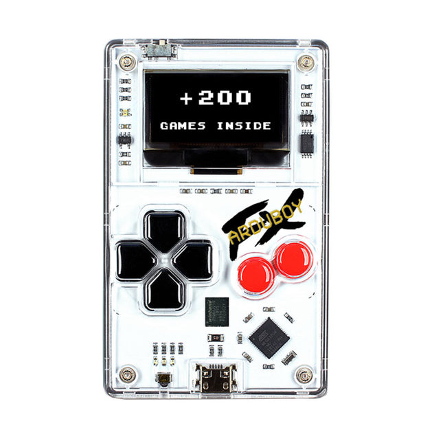
Arduboy FX
Arduboy is a miniture game development system the size of a credit card based on the popular open source Arduino platform. Learn to program/code with lots of tutorials and an active community of developers, develop and share your own games using Arduino software via the USB-Cable. Use your PC/Mac/Linux machine to download over 200 unique games created by members of the Arduboy Community.Features Processor: ATmega32u4 (same as Arduino Leonardo & Micro) Memory: 32 KB Flash, 2.5 KB RAM, 1 KB EEPROM Inputs: 6 Momentary Tactile Buttons Outputs: 128 x 64 1-bit OLED, 4 Ch. Piezo Speaker & Blinky LED Battery: 180 mAh Thin-Film Lithium Polymer Connectivity: Micro-USB 2.0 with built-in HID profile Programming: Arduino IDE, Arduboy Game Loader, GCC & AVRDude Open source gamingAnyone can make games for the Arduboy! Free online tutorials guide you through a step by step process on how to develop your own software! There are already plenty of examples to learn from. Ever wanted to create a level or map for your favorite game, or make your favorite character jump higher? Now is your chance!Super retroDesigned to remind you of a more simple time in the world of gaming, the Arduboy brings true 8-bit gaming into the 21st century with style. The black and white screen invites you to involve your imagination once again while gaming.Durable constructionA polycarbonate front, ultra thin circuit board, and stamped aluminum metal back is the ultimate combination. A rechargeable lithium polymer battery provides over 8 hours of battery life, and the same cable you use to charge can be used to upload new games! At only 5 mm thick, Arduboy can live in your pocket (or even wallet) and is thinner than nearly any mobile phone!Downloads Schematics GitHub Documentation
€ 74,95
Members € 67,46
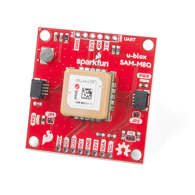
SparkFun SparkFun GPS Breakout - Chip Antenna, SAM-M8Q (Qwiic)
Additionally, this u-blox receiver supports I²C (u-blox calls this Display Data Channel), making it perfect for the Qwiic compatibility, so we don't have to use up our precious UART ports. Utilizing our handy Qwiic system, no soldering is required to connect it to the rest of your system. However, we still have broken out 0.1'-spaced pins if you prefer to use a breadboard. U-blox based GPS products are configurable using the popular but dense, windows program called u-centre. Plenty of different functions can be configured on the SAM-M8Q: baud rates, update rates, geofencing, spoofing detection, external interrupts, SBAS/D-GPS, etc. All of this can be done within the SparkFun Arduino Library! The SparkFun SAM-M8Q GPS Breakout is also equipped with an on-board rechargeable battery that provides power to the RTC on the SAM-M8Q. This reduces the time-to-first fix from a cold start (~30s) to a hot start (~1s). The battery will maintain RTC and GNSS orbit data without being connected to power for plenty of time. Features 72-Channel GNSS Receiver 2.5 m Horizontal Accuracy 18 Hz Max Update Rate Time-To-First-Fix: Cold: 26s Hot: 1s Max Altitude: 50,000 m Max G: ≤4 Max Velocity: 500 m/s Velocity Accuracy: 0.05 m/s Heading Accuracy: 0.3 degrees Time Pulse Accuracy: 30 ns 3.3 V VCC and I/O Current Consumption: ~29 mA Tracking GPS+GLONASS Software Configurable Geofencing Odometer Spoofing Detection External Interrupt Pin Control Low Power Mode Many others! Supports NMEA, UBX, and RTCM protocols over UART or I²C interfaces
€ 49,95
Members € 44,96
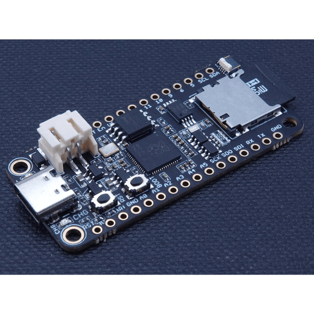
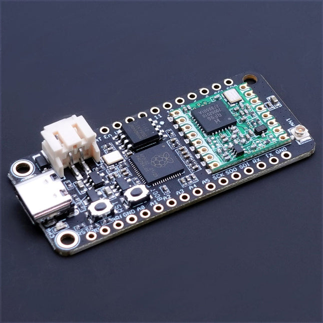
iLabs iLabs Challenger RP2040 SD/RTC
The Challenger RP2040 SD/RTC is an Arduino/CircuitPython compatible Adafruit Feather format microcontroller board based on the Raspberry Pi Pico chip. This board is equipped with an microSD card reader and a Real Time Clock making it super useful for data logging applications. MicroSD Card This board is equipped with a microSD card connector that will house standard microSD cards allowing your application to have many gigabytes of storage room for sensor data or what ever you want to place on it. Together with a fancy display you could also store cool images. Real Time Clock (RTC) MCP79410 is a highly integrated real time clock with nonvolatile memory and many other advanced features. These features include a battery switchover circuit for backup power, a timestamp to log power failures and digital trimming for accuracy. Using a low-cost 32.768 kHz crystal or other clock source, time is tracked in either a 12-hour or 24-hour format with an AM/PM indicator and timing to the second, minute, hour, day of the week, day, month and year. As an interrupt or wakeup signal, a multifunction open drain output can be programmed as an Alarm Out or as a Clock Out that supports 4 selectable frequencies. Specifications Microcontroller RP2040 from Raspberry Pi (133 MHz dual-core Cortex-M0) SPI One SPI channel configured I²C One I²C channel configured UART One UART channel configured Analog inputs 4 analog input channels Flash memory 8 MB, 133 MHz SRAM Memory 264 KB (divided into 6 banks) USB 2.0 controller Up to 12 MBit/s full speed (integrated USB 1.1 PHY) JST Battery connector 2.0 mm pitch On board LiPo charger 500 mA standard charge current RTC MCP79410 (uses I²C0 (Wire) for communication) SD Card One SPI channel used (uses SPI1 to connect to the SD socket) Dimensions 51 x 23 x 3,2 mm Weight 9 g Downloads Datasheet RunCPM image including HW I/O port support CPM File image for RunCPM Getting started with RunCPM for the Challenger RP2040 SD/RTC board CircuitPython download page
€ 17,95
Members € 16,16
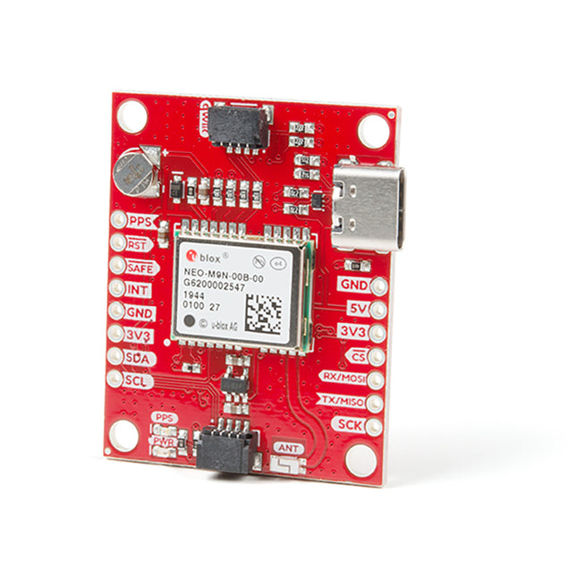
SparkFun SparkFun GPS Breakout - NEO-M9N, Chip Antenna (Qwiic)
Thanks to the onboard rechargeable battery, you'll have backup power enabling the GPS to get a hot lock within seconds! Additionally, this u-blox receiver supports I²C (u-blox calls this Display Data Channel), making it perfect for the Qwiic compatibility, so we don't have to use up our precious UART ports. Utilizing our handy Qwiic system, no soldering is required to connect it to the rest of your system. However, we still have broken out 0.1'-spaced pins if you prefer to use a breadboard. The NEO-M9N module detects jamming and spoofing events and can reports them to the host so that the system can react to such events. A SAW (Surface Acoustic Wave) filter combined with an LNA (Low Noise Amplifier) in the RF path is integrated into the NEO-M9N module, allowing normal operation even under strong RF interferences. U-blox based GPS products are configurable using the popular but dense, windows program called u-centre. Plenty of different functions can be configured on the NEO-M9N: baud rates, update rates, geofencing, spoofing detection, external interrupts, SBAS/D-GPS, etc. All of this can be done within the SparkFun Arduino Library! The SparkFun NEO-M9N GPS Breakout is also equipped with an on-board rechargeable battery that provides power to the RTC on the NEO-M9N. This reduces the time-to-first fix from a cold start (~24s) to a hot start (~2s). The battery will maintain RTC and GNSS orbit data without being connected to power for plenty of time. Features Integrated Chip Antenna 92-Channel GNSS Receiver 1.5m Horizontal Accuracy 25Hz Max Update Rate (4 concurrent GNSS) Time-To-First-Fix: Cold: 24 s Hot: 2 s Max Altitude: 80,000 m Max G: ≤4 Max Velocity: 500 m/s Velocity Accuracy: 0.05 m/s Heading Accuracy: 0.3 degrees Time Pulse Accuracy: 30 ns 3.3 V VCC and I/O Current Consumption: ~31 mA Tracking GPS+GLONASS Software Configurable Geofencing Odometer Spoofing Detection External Interrupt Pin Control Low Power Mode Many others! Supports NMEA, UBX, and RTCM protocols over UART or I²C interfaces
€ 69,95
Members € 62,96
iLabs iLabs Challenger RP2040 LoRa (EU868)
The Challenger RP2040 LoRa is an Arduino/CircuitPython compatible Adafruit Feather format microcontroller board based on the Raspberry Pi Pico (RP2040) chip.The transceiver features a LoRa long range modem that provides ultra-long range spread spectrum communication and high interference immunity whilst minimizing current consumption.LoRaThe integrated module LoRa module (RFM95W) can achieve a sensitivity of over -148 dBm utilizing a low cost crystal and bill of materials. The high sensitivity combined with the integrated +20 dBm power amplifier yields industry leading link budget making it optimal for any application requiring range or robustness. LoRa also provides significant advantages in both blocking and selectivity over conventional modulation techniques, solving the traditional design compromise between range, interference immunity and energy consumption.The RFM95W is connected to the RP2040 via SPI channel 1 and a few GPIO’s that is required for signaling. A U.FL connector is used to attach your LoRa antenna to the board. 168 dB maximum link budget +20 dBm – 100 mW constant RF output vs. V supply +14 dBm high efficiency PA Programmable bit rate up to 300 kbps High sensitivity: down to -148 dBm Bullet-proof front end: IIP3 = -12.5 dBm Excellent blocking immunity Low RX current of 10.3 mA, 200 nA register retention Fully integrated synthesizer with a resolution of 61 Hz FSK, GFSK, MSK, GMSK, LoRaTM and OOK modulation Built-in bit synchronizer for clock recovery Preamble detection 127 dB Dynamic Range RSSI Automatic RF Sense and CAD with ultra-fast AFC Packet engine up to 256 bytes with CRC Specifications Microcontroller RP2040 from Raspberry Pi (133 MHz dual-core Cortex-M0) SPI Two SPI channels configured (second SPI connected to RFM95W) I²C One I²C channel configured UART One UART channel configured Analog inputs 4 analog input channels Radio module RFM95W from Hope RF Flash memory 8 MB, 133 MHz SRAM memory 264 KB (divided into 6 banks) USB 2.0 controller Up to 12 MBit/s full speed (integrated USB 1.1 PHY) JST Battery connector 2.0 mm pitch On board LiPo charger 450 mA standard charge current Dimensions 51 x 23 x 3,2 mm Weight 9 g Downloads Datasheet Design files
€ 24,95
Members € 22,46
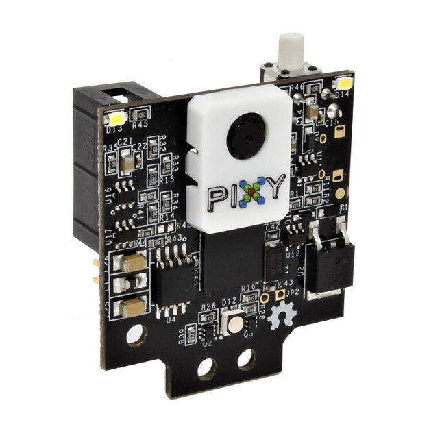
Charmed Labs Pixy2 CMUcam5 - Smart Vision Sensor
Pixy2 comes with various cables so that you can connect it with an Arduino or a Raspberry Pi out of the box. Furthermore, the I/O port offers several interfaces (SOI, I²C, UART, USB) to plug your Pixy2 in most boards. Here you can find different project ideas to get you started and here is the software and libraries you will need to programme your Pixy2.


