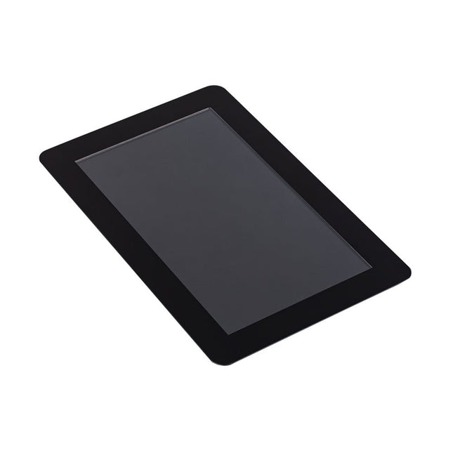
LILYGO T-Display-S3 ESP32-S3 1.9-inch ST7789 LCD Display Development Board WiFi Bluetooth 5.0 Wireless Module 170x320 Resolution
T-Display-S3 is a development board whose main control chip is ESP32-S3. It is equipped with a 1.9-inch LCD color screen and two programmable buttons. Communication using the I8080 interface Retains the same layout design as T-Display. You can directly use ESP32S3 for USB communication or programming.
Specifications
MCU
ESP32-S3R8 Dual-core LX7 microprocessor
Wireless Connectivity
Wi-Fi 802.11, BLE 5 + BT Mesh
Programming Platform
Arduino IDE Micropython
Flash
16 MB
PSRAM
8 MB
Bat voltage detection
IO04
Onboard functions
Boot + Reset + IO14 Button
Display
1.9" diagonal, Full-color TFT LCD
Drive Chip
ST7789V
Resolution
170 x 320 (RGB) 8-Bit Parallel Interface
Working power supply
3.3 V
Support
STEMMA QT/Qwiic
Connector
JST-GH 1.25 mm 2-pin
Downloads
Pinout
GitHub
This 0.96-inch monochrome graphical OLED display, with a resolution of 128 x 32 pixels, is mounted on a 28 x 28 mm PCB. The active display area is 11 x 23 mm. It includes a 4-pin connector that supports the I²C bus (with SCL and SDA signals). The display is compatible with both 5 V and 3.3 V applications.
Specifications
Display size: 0.96"
Resolution: 128 x 32 pixels
Board size: 28 x 28 mm
Effective display surface: 11 x 23 mm
Visual angle: >160°
Input voltage: 3.3 V ~ 6 V
Wide voltage support: 3.3 V, 5 V
Viewing angle: >160°
Drive IC: SSD1306
Operating temperature: -30 to 80°C
I²C
Signals: SCL, SDA
I²C address: 0x78 (or 0x3c, default) or 0x7a (or 0x3d).
Note: I²C addresses can (unfortunately) be specified in two ways: including R/W bit or not. Therefore 0x78 (0x7a) including the R/W bit is equal to 0x3c (0x3d) without R/W bit.
OLED Advantages
Smaller volume
Ultra-low power consumption
High Contrast
Display dot self-luminous
Wide voltage support
Warning: The display’s glass is fragile, please be careful while handling it. If the glass is broken, the screen will not work well.
ILI9341 is a 262144-color single-chip SOC driver for a TFT liquid crystal display with resolution of 240x320 dots (RGB), comprising a 720-channel source driver, a 320-channel gate driver, 172800 bytes GRAM for graphic display data of 240x320 dots (RGB), and power supply circuit.ILI9341 supports parallel 8-/9-/16-/18-bit data bus MCU interface, 6-/16-/18-bit data bus RGB interface and 3-/4-line serial peripheral interface (SPI).The moving picture area can be specified in internal GRAM by window address function. The specified window area can be updated selectively, so that moving picture can be displayed simultaneously independent of still picture area.ILI9341 can operate with 1.65V ~ 3.3V I/O interface voltage and an incorporated voltage follower circuit to generate voltage levels for driving an LCD.ILI9341 supports full color, 8-color display mode and sleep mode for precise power control by software and these features make the ILI9341 an ideal LCD driver for medium or small size portable products such as digital cellular phones, smart phone, MP3 and PMP where long battery life is a major concern.Features
Display resolution: 240 x 320 (RGB)
Output: 720 source outputs | 320 gate outputs | Common electrode output (VCOM)
a-TFT LCD driver with on-chip full display RAM: 172,800 bytes
System Interface
8-bits, 9-bits, 16-bits, 18-bits interface with 8080-Ⅰ/8080- Ⅱ series MCU
6-bits, 16-bits, 18-bits RGB interface with graphic controller
3-line / 4-line serial interface
Display mode:
Full color mode (Idle mode OFF): 262K-color
Reduced color mode (Idle mode ON): 8-color
Power saving modes:
Sleep mode
Deep standby mode
On chip functions:
VCOM generator and adjustment
Timing generator
Oscillator
DC/DC converter
Line/frame inversion
1 preset Gamma curve with separate RGB Gamma correction
Content Adaptive Brightness Control
MTP (3 times):
8-bits for ID1, ID2, ID3
7-bits for VCOM adjustment
Low-power consumption architecture
Low operating power supplies:
VDDI = 1.65V ~ 3.3V (logic)
VCI = 2.5V ~ 3.3V (analog)
LCD Voltage drive:
Source/VCOM power supply voltage
AVDD - GND = 4.5V ~ 5.5V
VCL - GND = -2.0V ~ -3.0V
Gate driver output voltage
VGH - GND = 10.0V ~ 20.0V
VGL - GND = -5.0V ~ -15.0V
VGH - VGL 3 ≦ 2V
VCOM driver output voltage
VCOMH = 3.0V ~ (AVDD – 0.5)V
VCOML = (VCL+0.5)V ~ 0V
VCOMH - VCOML ≦ 6.0V
Operate temperature range: -40℃ to 85℃
This ESP32 terminal is a microcontroller based on the ESP32 master. It adopts Xtensa 32-bit LX7 dual-core processor with a main frequency of up to 240 Mhz, supports 2.4 GHz Wi-Fi and Bluetooth 5 (LE), and can easily handle common edge terminal device application scenarios, such as industrial control, agricultural production environment detection and processing, intelligent logistics monitoring, smart home scenarios and more.
The ESP32 module also has a 3.5-inch parallel RGB interface capacitive touch screen with a resolution of 320x480 to ensure perfect image output at a frame rate 60 FPS. The 4 Crowtail interfaces on the back of this terminal can be used with Crowtail series sensors, plug and play, and create more interesting projects quickly and conveniently. In addition, it is also equipped with an SD card slot for extended storage (SPI leads) and a buzzer function.
The ESP32 touchscreen supports ESP-IDF and Arduino IDE development and is compatible with Python/MicroPython/Arduino. It also supports LVGL, which is the most popular free and open-source embedded graphics library to create beautiful UIs for any MCU, MPU, and display type. Now it has also obtained the official certification of LVGL. LVGL's board certificate shows that the boards can be easily used with LVGL and has decent performance for UI applications. The onboard charging circuit and lithium battery interface can use the type-C power supply interface to supply power and charge the battery at the same time, providing more outdoor scene expansion possibilities.
Features
Integrated ESP32-S3 module, which is support 2.4 GHz Wi-Fi and Bluetooth 5 (LE)
LCD 3.5 inches parallel TFT-LCD with 320x480 resolution
Compatible with Arduino/Python/MicrmoPython
Mature software support, support ESP-IDF and Arduino IDE development
Support open-source Graphics Library-LVGL
Support 1T1R mode, data rate up to 150 Mbps, Wireless Multimedia (WMM)
Perfect security mechanism, support AES-128/256, Hash, RSA, HMAC, digital signatures and secure boot
Onboard charging chip and interface, use type-C interface to charge
With 4 Crowtail interfaces (HY2.0-4P connector), plug and play with various Crowtail sensor
Applications
Smart Home
Industrial Control
Medical Monitor
Home Appliance Display
Logistics Monitoring
Specifications
ESP32-S3 module with 16 MB Flash and 8 MB PSRAM
Wi-Fi Protocol: 802.11b/g/n (802.11n up to 150 Mbps) Wi-Fi Frequency Range: 2.402-2.483 Ghz
Support Bluetooth 5
With 4 Crowtail interfaces (HY2.0-4P connector) and onboard Micro TF card slot
3.5-inch TFT LCD RGB true color LCD screen with 320x480 resolution
Driver chip: ILI9488 (16-bit parallel line)
Capacitive touch panel controller IC FT6236 series
Operating Voltage: DC 5 V-500 mA
Sleep current:
USB power supply: 6.86 mA
Lithium battery power supply: 3.23 mA
LiPo Battery Interface: PH2.0
Operating temperature: -10°C ~ 65°C
Active Area: 73.63 x 49.79 mm (L x W)
Dimensions: 106 x 66 x 13 mm (L x W x H)
Included
1x 3.5-inch ESP RGB Display with Acrylic Shell
1x USB-C Cable
Downloads
Wiki
Schematic Diagram
16 learning Lessons for LVGL
Source code
Lesson code
LVGL Reference
ESP32-S3 Datasheet
ILI9488 Datasheet
Capacitive Touch Display Data
Scrolling text display with eight 8 x 8 LED dot matrix displays (512 LEDs in total). Built around an ESP-12F Wi-Fi module (ESP8266-based) programmed in the Arduino IDE. ESP8266 web server allows control of displayed text, scroll delay and brightness with a mobile phone or other Wi-Fi-connected (portable) device. Features 10 MHz Serial Interface Individual LED Segment Control Decode/No-Decode Digit Selection 150 µA Low-Power Shutdown (Data Retained) Digital and Analog Brightness Control Display Blanked on Power-Up Drive Common-Cathode LED Display Slew-Rate Limited Segment Drivers for Lower EMI (MAX7221) SPI, QSPI, MICROWIRE Serial Interface (MAX7221) 24-Pin DIP and SO Packages
Features 480 x 320 resolution, IPS screen, 65K colors, clear and colorful displaying effect Dedicated touch controller, bringing more smooth touching effect than AD-controlled solutions MicroSD card slot for storing images and direct displaying them easily Programmable backlight control, power saving Comes with development resources and manual (Raspberry Pi Pico C/C++ and MicroPython examples) Specifications Operating voltage 5 V Resolution 480 x 320 pixels Communication interface SPI Display size 73.44 x 48.96 mm Display panel IPS Pixel size 0.153 x 0.153 mm Driver ILI9488 Dimensions 86.00 x 57.20 mm Touch controller XPT2046 Downloads Wiki
This DIY Color Display Kit is a fun and educational project for makers of all ages. It is a great way to learn about electronics, programming, and improve your soldering skills.
Microcontroller
As this kit ships with the ePulse Feather ESP32 development board, the kit thereby inherits all the great features of said devkit.
Display
The large 3.5" 320x480 color display also sports a high-precision capacitive touch interface. Contrary to resistive touch interfaces that often work best when using a stylus this auto-calibrated module offers a smartphone-like user experience.
Connector PCB
The connectors for the display are already pre-assembled on the connector PCB, as those require a more experienced hand at the soldering iron. Hence, for the inexperienced solderer this offers the best of both worlds. Also, you may choose to not add the on-off switch or the Grove connector; both are optional.
The connector PCB offers extendability in two ways: the broken out pins of the microcontroller and the connector for the Grove system.
Specifications
Microcontroller
ESP32
Module
ePulse Feather
Display Resolution
320 x 480
Display Driver
ILI9488
Touch Display
Capacitive
Included
1x ePulse Feather, low-power ESP32 development board
1x 3.5" 320x480 Color Display (ILI9488, TFT) with capacitive touch Interface (FT6236) Color Kit Grande Connector Board
1x Custom connector PCB to connect the ESP32 and the display Header Pins
1x Set of special pin headers (to be soldered to connector PCB Color Kit Power Switch)
1x On-off switch (to be optionally soldered to connector PCB SMD Grove Connector)
1x Grove connector (to be optionally soldered to connector PCB Color Kit Grande Foam Stickers)
4x Double-sided foam adhesive to secured display to PCB
Downloads
Schematics
Documentation
The Raspberry Pi Touch Display 2 is a 7-inch touchscreen designed for Raspberry Pi, perfect for interactive projects like tablets, entertainment systems, and information dashboards. Raspberry Pi OS includes touchscreen drivers that support five-finger touch and an on-screen keyboard, allowing complete functionality without a physical keyboard or mouse.
Connecting the 720 x 1280 display to your Raspberry Pi requires just two connections: power from the GPIO port and a ribbon cable to the DSI port, compatible with all Raspberry Pi models except the Raspberry Pi Zero line.
Specifications
Display
7 inch TFT (720 x 1280 pixels)
Active area
88 x 155 mm
Touch panel
True multi-touch capacitive touch panel, supporting five-finger touch
Surface treatment
Anti-glare
Color configuration
RGB-stripe
Backlight type
LED B/L
Included
1x Raspberry Pi Touch Display 2
1x 22-way to 15-way FFC for Raspberry Pi 5
1x 15-way to 15-way FFC for Raspberry Pi 4 and older
1x GPIO connector cable
8x M2.5 screws
Downloads
Datasheet
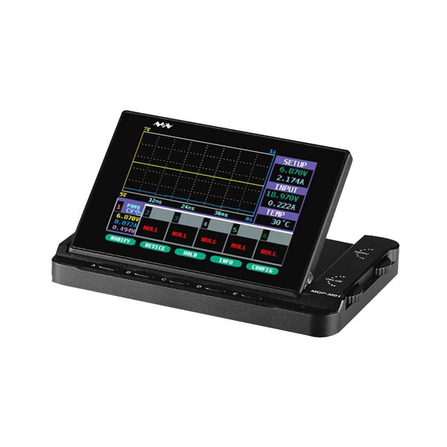
Specifications Size: 0.96 inch Resolution: 128 x 64 Visual Angle: >160 ° Input Voltage: 3.3 V ~ 6 V Wide voltage support: 3.3 V, 5 V Viewing angle: >160 Only Need 2 I/O Port to Control Drive IC: SSD1306 Operating temperature: -30 °C to 80 °C OLED Advantages Smaller volume Ultra-low power consumption High contrast Display dot self-luminous Broad voltage support Independent communication method via SPI or IIC 128x64 Dot matrix Broad visual angle: maximum visual angle 160° Industrial-grade operating temperature: -30 ~ 70 °C Warning: The display’s glass is very thin, please be careful while using it. If The glass is broken, display will not work well.
Features 2.13' capacitive touch e-Paper display, 5-point touch, 250×122 pixels Supports waken up by user-defined gesture No backlight, keeps displaying last content for a long time even when power down Ultra low power consumption, basically power is only required for refreshing Standard Raspberry Pi 40PIN GPIO extension header, supports Raspberry Pi Zero / Zero W Comes with development resources and manual (examples for Raspberry Pi) Included 1x 2.13inch Touch e-Paper HAT 1x ABS case 1x Screwdriver 1x Thermal tape 1x Rubber feet 4pcs 2x Screws Downloads Documentation
2x16 Character LCD Module (blue/white)
Pin No. Pin Name Descriptions 1 VSS Ground 2 VDD Supply voltage for logic 3 V0 Input voltage for LCD 4 RS Data / Instruction Regster Select (H : Data signal, L : Instruction signal) 5 R/W Read / Write (H : Read mode, L : Write mode) 6 E Enable signal 7 DB0 Data bit 0 8 DB1 Data bit 1 9 DB2 Data bit 2 10 DB3 Data bit 3 11 DB4 Data bit 4 12 DB5 Data bit 5 13 DB6 Data bit 6 14 DB7 Data bit 7 15 LED_A Backlight Anode 16 LED_K Backlight Cathode
The ESP32-S3 Parallel TFT not only offers more SRAM and ROM (compared to the S2 version), but with Bluetooth 5.0 it is also suitable for applications such as local monitoring and controlling.
The built-in LCD driver ILI9488 uses 16-bit parallel lines to communicate with ESP32-S3, the main clock can be up to 20 MHz, which makes the display smooth enough for video displays. With this display, you can create more IoT display projects.
Features
Controller: ESP32-S3-WROOM-1, PCB Antenna, 16 MB Flash, 2 MB PSRAM, ESP32-S3-WROOM-1-N16R2
Wireless: Wifi & Bluetooth 5.0
LCD: 3.5-inch TFT LCD
Resolution: 480x320
Color: RGB
LCD Interface: 16-bit parallel
LCD Driver: ILI9488
Touch Panel: Capacitive
Touch Panel Driver: FT6236
USB: Dual USB Type-C (one for USB-to-UART and one for native USB)
UART to UART Chip: CP2104
Power Supply: USB Type-C 5.0 V (4.0 V~5.25 V)
Button: Flash button and reset button
Mabee Interface: 1x I²C, 1x GPIO
Backlight Controller: Yes
MicroSD: Yes
Arduino support: Yes
Type-C Power Delivery: Not supported
Operation temperature: -40℃ to +85℃
Dimension: 66 x 84.3 x 12 mm
Weight: 52 g
Downloads
ESP32-S3 Datasheet
GitHub
Wiki
LVGL Demo Code
This display features an IPS resolution of 480x480 with capacitive touch and a frame rate of up to 75 FPS. It is very bright and has 65,000 colors. The mechanical rotary encoder supports clockwise/counterclockwise rotation and also supports the entire pressing process, which can usually be used to confirm the process. The display module is based on ESP32-S3 with WiFi & Bluetooth 5.0 to easily connect to the Internet for IoT projects. It can be powered and programmed directly via the USB port. It also has two expansion ports, I²C and UART. Specifications Controller ESP32-S3 WROOM-1-N16R8 (16 MB Flash, 8 MB PSRAM, PCB antenna) Wireless WiFi & Bluetooth 5.0 Resolution 480x480 LCD 2.1' IPS LCD, 65K color LCD driver ST7701S Frame rate >70 FPS LCD interface RGB 565 Touch panel 5-points capacitive touch Touch panel driver CST8266 USB USB-C native Interfaces 1x I²C, 1x UART (1.25 mm, 4-pin connector) Arduino support Yes Downloads Wiki Usage with Squareline/LVGL GitHub Datasheet_ESP32-S3-WROOM-1
Lora technology and Lora devices have been widely used in the field of the Internet of Things (IoT), and more and more people are joining and learning Lora development, making it an indispensable part of the IoT world. To help beginners learn and develop Lora technology better, a Lora development board has been designed specifically for beginners, which uses RP2040 as the main control and is equipped with the RA-08H module that supports Lora and LoRaWAN protocols to help users realize development. RP2040 is a dual-core, high-performance, and low-power ARM Cortex-M0+ architecture chip, suitable for IoT, robots, control, embedded systems, and other application fields. RA-08H is made from the Semtech-authorized ASR6601 RF chip, which supports the 868 MHz frequency band, has a 32 MHz MCU built-in, which has more powerful functions than ordinary RF modules, and also supports AT command control. This board retains various functional interfaces for development, such as the Crowtail interface, the common PIN to PIN header that leads out GPIO ports, and provides 3.3 V and 5 V outputs, suitable for the development and use of commonly used sensors and electronic modules on the market. In addition, the board also reserves RS485 interface, SPI, I²C, and UART interfaces, which can be compatible with more sensors/modules. In addition to the basic development interfaces, the board also integrates some commonly used functions, such as a buzzer, a custom button, red-yellow-green three-color indicator lights, and a 1.8-inch SPI interface LCD screen with a resolution of 128x160. Features Uses RP2040 as the main controller, with two 32-bit ARM Cortex M0+ processor cores (dual-core), and provides more powerful performance Integrates the RA-08H module with 32 MHz MCU, supports the 868 MHz frequency band and AT command control Abundant external interface resources, compatible with Crowtail series modules and other common interface modules on the market Integrates commonly used functions like buzzer, LED light, LCD display and custom button, making it more concise and convenient when creating projects Onboard 1.8-inch 128x160 SPI-TFT-LCD, ST7735S driver chip Compatible with Arduino/Micropython, easy to carry out different projects Specifications Main Chip Raspberry Pi RP2040, built-in 264 KB SRAM, onboard 4 MB Flash Processor Dual Core Arm Cortex-M0+ @ 133 MHz RA-08H Frequency band 803-930 MHz RA-08H Interface External antenna, SMA interface or IPEX first-generation interface LCD Display Onboard 1.8-inch 128x160SPI-TFT-LCD LCD Resolution 128x160 LCD Driver ST7735S (4-wire SPI) Development environment Arduino/MicroPython Interfaces 1x passive buzzer 4x user-defined buttons 6x programmable LEDs 1x RS485 communication interface 8x 5 V Crowtail interfaces (2x analog interfaces, 2x digital interfaces, 2x UART, 2x I²C) 12x 5 V universal pin header IO 14x 3.3 V universal pin header IO 1x 3.3 V/5 V switchable SPI 1x 3.3 V/5 V switchable UART 3x 3.3 V/5 V switchable I²C Working input voltage USB 5 V/1 A Operating temperature -10°C ~ 65°C Dimensions 102 x 76.5 mm (L x W) Included 1x Lora RA-08H Development Board 1x Lora Spring Antenna (868 MHz) 1x Lora Rubber Antenna (868 Mhz) Downloads Wiki
Pico Cube is a 4x4x4 LED cube HAT for Raspberry Pi Pico with 5 VDC operating voltage. Pico cube, a monochromatic Blue with 64 LEDs, is a fun way to learn programming. It is designed to perform incandescent operations with low energy consumptions, robust outlook, and easy installation that make people/kids/users learn the effects of LED lights with a different pattern of colors via the combination of software and hardware i.e. Raspberry Pi Pico.
Features
Standard 40 Pins Raspberry Pi Pico Header
GPIO Based Communication
64 High-Intensity Monochromatic LEDs
Individual LED access
Each Layer Access
Specifications
Operating Voltage: 5 V
Color: Blue
Communication: GPIO
LEDs: 64
Included
1x Pico Cube Base PCB
4x Layer PCB
8x Pillar PCB
2x Male Berg (1 x 20)
2x Female Berg (1 x 20)
70 LEDs
Note: Raspberry Pi Pico is not included.
Downloads
GitHub
Wiki
Standard 2x16 LCD (see Elektor Labs Preferred Parts - ELPP) with the following specifications: 2 rows, 16 characters wide 5 x 7 dots font and cursor Yellow-green LCD with yellow-green LED backlight HD44780 equivalent LCD controller High contrast Readable in sunlight 16 pin Connection port is 2.54 mm (0.1') pitch, single row for easy breadboarding and wiring pinning (left-to-right): 1-14,A,K Single LED backlight included; Easily dimmed with a resistor or via PWM; Uses much less power than electroluminescent backlights Can be fully controlled with only 6 digital lines(in 4-bit bus mode) 5V DC operating voltage Module dimension: 80 x 36 x 10 mm Viewing area size: 64.5x 15 mm
This ESP32 S3 7-inch IPS 5-point capacitive touch display with an ultra-high resolution of 1024 x 600 pixels is ideal for IoT applications. It is ideal for applications such as home automation. An integrated SD card enables recording/playback of stored data. There are also two Mabee/Grove connectors to connect various sensors to this board to create personal prototype projects in no time.
Specifications
Controller: ESP32-S3-WROOM-1, PCB antenna, 16 MB Flash, 8 MB PSRAM, ESP32-S3-WROOM-1-N16R8
Wireless: Wifi & Bluetooth 5.0
LCD: 7-inch High Lightness IPS
FPS: >30
Resolution: 1024 x 600
LCD interface: RGB 565
Touch panel: Capacitive 5-point touch
Touch panel driver: GT911
USB: Dual USB-C (one for USB-to-UART and one for native USB)
UART to UART chip: CP2104
Power supply: USB-C 5.0 V (4.0 V~5.25 V)
Button: Flash button and reset button
Mabee interface: 1x I²C, 1x GPIO
MicroSD: Yes
Arduino support: Yes
Type-C Power Delivery: Not supported
Operation temperature: −40 to +85°C
Downloads
Wiki
GitHub
ESP32-S3 Datasheet
Screen touch coordinates calibration
Features Fully assembled and tested Nixie clock Six tested IN-14 Nixie tubes mounted to the clock base Two neon colon tubes installed into the clock base 12 V DC power adapter IR remote control Built-in proximity sensor User manual This clock is a combination of modern technologies and vintage Nixie tubes. It is a perfect gift for your friend and definitely will fit into any interior. Warm glowing of the neon will fill your house with soft orange light at night and will serve as a night light. The clock is built with 6 numeric IN-14 Nixie tubes. A built-in RGB LED backlight (with 10 levels for each channel) allow you to set your favorite color. Time accuracy is provided with built-in RTC (Real Time Clock DS3231) module and backuped with CR2032 battery while the clock is powered off. At the end of each minute (could be configured to be set from 1-5 minutes period or completely disabled) starts 'Slot Machine' feature that helps to prevent cathode poisoning effect. It scrolls over all numbers from 0 to 9. It is necessary to prolong tubes lifespan. Current date is shown each 1-5-th minute in 3 various formats: DD:MM:YY, MM:DD:YY or YY:MM:DD. The current time could be configured to 12 or 24 hour format. There are also three modes for colon tubes: Blinks once a second (is set as a default option) Permanently OFF Permanently ON The clock could be set to beep once an hour (when hour starts). The clock also has an alarm feature. All settings are stored in non-volatile memory (settings are restored after power-offs). Dimensions Height: 20 mm Width: 175 mm Length: 70 mm Tube height: 45 mm
With the help of the Grove I²C connector, only 2 signal pins and 2 power pins are needed. You don't even need to care about how to connect these pins. Just plug it into the I²C interface on Seeeduino or Arduino/Raspberry Pi+baseshield via the Grove cable.
No complicated wiring, no soldering, no need to worry about burning the LCD caused by the wrong current limiting resistor. Easy peasy.
Specifications
Battery: Exclude
Input Voltage: 5 V
Dimensions: 83 x 44 x 13 mm
Weight: 42 g
The RGB matrix module is equipped with 4096 LEDs and is characterized by a particularly small grid size of only 3mm. This makes it ideal for pictorial representations. Video sequences can also be displayed.
The module is supplied with the necessary cables. It is perfectly suited in combinations with single board computers like the Raspberry Pi, Arduino, BBC Microbit and many more.
Specifications
Display
RGB-LED
Resolution
64 x 64
Amount of LED
4096 LEDs
LED Size
3 mm Pitch
Supply Voltage
5 V
Max. Power Input
40 W
Control
1/32 Scan
Operating Temperature
-20~55°C
Viewing Angle
140°
Pixel Density
111111 Pixel/m²
Dimensions
192 x 192 x 14 mm
Weight
246 g
Items Shipped
LED-Matrix, Kabel
Downloads
Datasheet
Manual
The 1.28' LCD display convinces with its high-resolution IPS display and its circular display surface. With a color depth of 65,000 colors, the display is of particularly high quality. Due to the control via the SPI interface, the display is ideally suited for use as an output device on microcontrollers and single board computers. Specifications Interface 4-Wire SPI LCD type IPS LCD Display size 1.28' - Ø 32.4 mm Resolution 240 x 240 Pixels Display controller GC9A01 Depth of color 65,000 Operating voltage 3.3/5 V Dimensions 40 x 37 x 10 mm Weight 20 g Downloads Datasheet Manual
This display correspond to the Nokia 5110 norm which makes it perfectly to display data or graphs of measured values on a microcontroller or a single-board computer. Additionally, the display is compatible to all Raspberry Pi, Arduino, CubieBoard, Banana Pi and microcontroller without additional effort. Specifications Chipset Philips PCD8544 Interface SPI Resolution 84 x 48 Pixels Power supply 2.7-3.3 V Special features Backlight Compatible to Raspberry Pi, Arduino, CubieBoard, Banana Pi and microcontroller Dimensions 45 x 45 x 14 mm Weight 14 g
The Giga Display Shield is a touch screen solution designed to effortlessly deploy graphic interfaces in your projects. Leveraging the new pin header connector in the middle of Giga R1 WiFi, this shield offers seamless integration and enhanced functionalities.
With the Giga Display Shield, you gain access to an array of features, including a digital microphone, 6-axis IMU, and Arducam connector. These added capabilities allow you to fully utilize the other 54 available pins, making it incredibly convenient to create handheld devices or dashboards to control your project.
Specifications
Display
KD040WVFID026-01-C025A
Size
3.97”
Resolution
480x800 RGB
Color
16.7M
Touch Mode
Five points and Gestures
Interface
I²C
Sensors
IMU
BMI270
Microphone
MP34DT06JTR
Downloads
Datasheet
Schematics