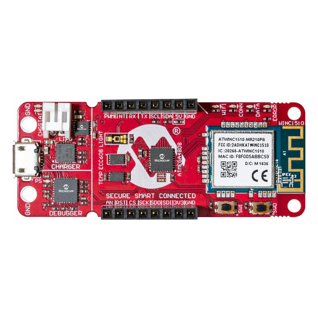
The AVR-IoT WA development board combines a powerful ATmega4808 AVR MCU, an ATECC608A CryptoAuthentication secure element IC and the fully certified ATWINC1510 Wi-Fi network controller – which provides the most simple and effective way to connect your embedded application to Amazon Web Services (AWS). The board also includes an on-board debugger, and requires no external hardware to program and debug the MCU.
Out of the box, the MCU comes preloaded with a firmware image that enables you to quickly connect and send data to the AWS platform using the on-board temperature and light sensors. Once you are ready to build your own custom design, you can easily generate code using the free software libraries in Atmel START or MPLAB Code Configurator (MCC).
The AVR-IoT WA board is supported by two award-winning Integrated Development Environments (IDEs) – Atmel Studio and Microchip MPLAB X IDE – giving you the freedom to innovate with your environment of choice.
Features
ATmega4808 microcontroller
Four user LED’s
Two mechanical buttons
mikroBUS header footprint
TEMT6000 Light sensor
MCP9808 Temperature sensor
ATECC608A CryptoAuthentication™ device
WINC1510 WiFi Module
On-board Debugger
Auto-ID for board identification in Atmel Studio and Microchip MPLAB X
One green board power and status LED
Programming and debugging
Virtual COM port (CDC)
Two DGI GPIO lines
USB and battery powered
Integrated Li-Ion/LiPo battery charger
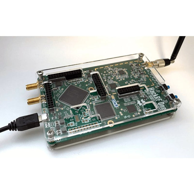
This clear acrylic case is the official case for the HackRF One board. It can replace the standard black plastic case of the HackRF One.
Assembly Instructions
Use a guitar pick or spudger to extract the HackRF One circuit board from the black plastic case.
Insert one long screw into each corner of the bottom acrylic panel. Secure each long screw with a short (5 mm) spacer on the opposite side of the panel.
Place the HackRF One circuit board (facing up) on top of the bottom panel, fitting the ends of the long screws through the corner mounting holes of the circuit board.
Secure the circuit board with one long (6 mm) spacer in each corner.
Place the top acrylic panel on top of the circuit board, aligning the cutouts with the circuit board’s expansion headers.
Secure each corner with a short screw.
Note: Do not overtighten! Hand-tighten only at every step.
Specifications
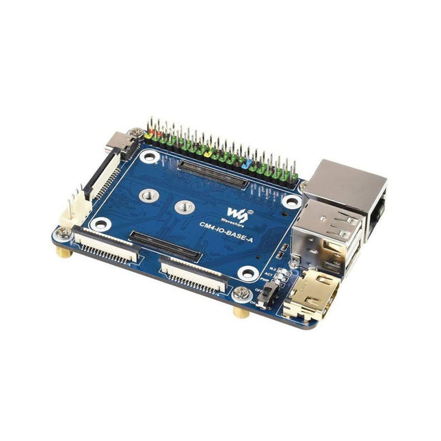
CM4 socket
Suitable for all variants of Compute Module 4
Networking
Gigabit Ethernet RJ45 connectorM.2 M KEY, supports communication modules or NVME SSD
Connector
Raspberry Pi 40-PIN GPIO header
USB
2x USB 2.0 Type A2x USB 2.0 via FFC connector
Display
MIPI DSI display port (15-pin 1.0 mm FPC connector)
Camera
2x MIPI CSI-2 camera port (15-pin 1.0 mm FPC connector)
Video
2x HDMI port (including one port via FFC connector), supports 4K 30fps output
RTC
N/A
Storage
MicroSD card socket for Compute Module 4 Lite (without eMMC) variants
Fan header
No fan control, 5 V
Power input
5 V
Dimensions
85 x 56 mm
Included
1x CM4-IO-BASE-A
1x SSD mounting screw
Downloads
Wiki
Add colors to your projects with this collection of red, green, yellow, blue and white LEDs. They come with various current limiting resistors in order to protect the parts and control the brightness.Included
10 mm LEDs
1x red
1x green
1x yellow
1x blue
1x white
5 mm LEDs
5x red
5x green
5x yellow
5x blue
5x white
3 mm LEDs
5x red
5x green
5x yellow
5x blue
5x white
25x 330 Ω resistors
10x 1 kΩ resistors
10x 10 kΩ resistors
10x 100 kΩ resistors
10x 1 MΩ resistors
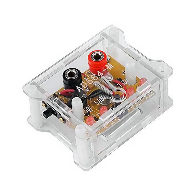
The AD584 4-ch Voltage Reference Module is designed to provide stable and accurate reference voltages of 2.5 V, 5 V, 7.5 V, and 10 V. It incorporates the AD584 integrated circuit, known for its high accuracy and stability.
Features
Multiple Output Voltages: The module can output four different reference voltages (2.5 V, 5 V, 7.5 V, and 10 V) accessible through a single port.
Microcontroller-based Switching: An onboard microcontroller facilitates switching between the four voltage outputs, with LED indicators displaying the active selection.
User-Friendly Operation: A single button allows for easy cycling through the available reference voltages.
Transparent Housing: The module is encased in a transparent housing, offering protection while allowing users to view the internal components.
Power Supply Options: It can be powered via a built-in lithium battery (not included) or through a 5 V DC input. A charging indicator provides status updates during charging.
Output Interface: Equipped with 4mm banana sockets for secure and reliable connections.
Included
1x AD584 4-ch Voltage Reference Module with Housing
Downloads
Datasheet
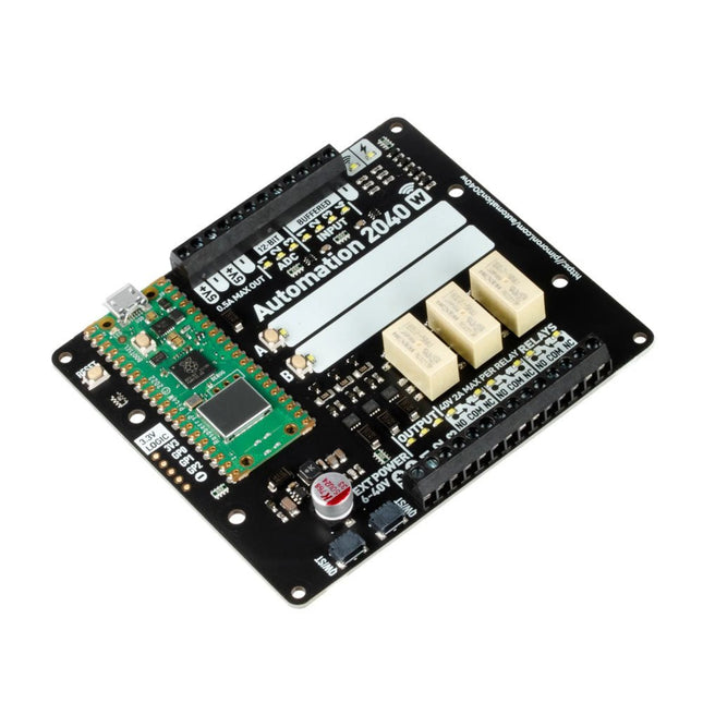
An all-in-one, Pico W powered industrial/automation controller with 2.46 GHz wireless connectivity, relays and a plethora of inputs and outputs. Compatible with 6 V to 40 V systems.
Automation 2040 W is a Pico W / RP2040 powered monitoring and automation board. It contains all the great features from the Automation HAT (relays, analog channels, powered outputs and buffered inputs) but now in a single compact board and with an extended voltage range so you can use it with more devices. Great for controlling fans, pumps, solenoids, chunky motors, electronic locks or static LED lighting (up to 40 V).
All the channels (and the buttons) have an associated indicator LED so you can see at a glance what's happening with your setup, or test your programs without having hardware connected.
Features
Raspberry Pi Pico W Aboard
Dual Arm Cortex M0+ running at up to 133 Mhz with 264 kB of SRAM
2 MB of QSPI flash supporting XiP
Powered and programmable by USB micro-B
2.4 GHz wireless
3x 12-bit ADC inputs up to 40 V
4x digital inputs up to 40 V
3x digital sourcing outputs at V+ (supply voltage)
4 A max continuous current
2 A max current at 500 Hz PWM
3x relays (NC and NO terminals)
2 A up to 24 V
1 A up to 40 V
3.5 mm screw terminals for connecting inputs, outputs and external power
2x tactile buttons with LED indicators
Reset button
2x Qw/ST connectors for attaching breakouts
M2.5 mounting holes
Fully assembled
No soldering required.
C/C++ and MicroPython libraries
Schematic
Dimensional drawing
Power
Board is compatible with 12 V, 24 V and 36 V systems
Requires supply 6-40 V
Can provide 5 V up to 0.5 A for lower voltage applications
Software
Pirate-brand MicroPython
Getting Started with Raspberry Pi Pico
MicroPython examples
MicroPython function reference
C++ examples
C++ function reference
Getting Started with Automation 2040 W
The SparkFun RedBoard Qwiic is an Arduino-compatible board that combines features of different Arduinos with the Qwiic Connect System.
Features
ATmega328 microcontroller with Optiboot Bootloader
R3 Shield Compatible
CH340C Serial-USB Converter
3.3 V to 5 V Voltage Level Jumper
A4 / A5 Jumpers
AP2112 Voltage Regulator
ISP Header
Input voltage: 7 V - 15 V
1 Qwiic Connector
16 MHz Clock Speed
32 k Flash Memory
All SMD Construction
Improved Reset Button
Features
Compatible with Raspberry Pi 4 only
Cutout in lid for 40x30mm heatsink or Fan SHIM
Super-slimline profile
Fully HAT-compatible
Protects your beloved Pi
Clear top and base leave Raspberry Pi 4 visible
GPIO cut-out
Handy laser-etched port labels
Leaves all ports accessible
Made from lightweight, high-quality, cast acrylic
Great for hacking and tinkering!
Made in Sheffield, UK
Weighing just over 50 grams, the case is lightweight and ideal for mounting to any surface. No tools are required for assembly or disassembly. The dimensions are: 99 × 66 × 15 mm.
In the video below you can see a quick assembly guide.
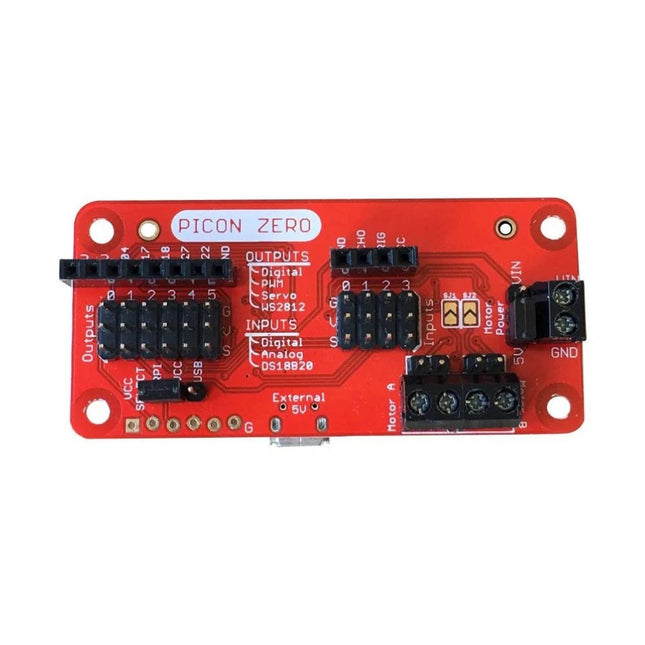
The Picon Zero is an add-on for the Raspberry Pi. It has the same size as a Raspberry Pi Zero, making it ideal to function as a pHat. Of course, it can be used on any other Raspberry Pi via a 40-pin GPIO connector.
As well as two full H-Bridge motor drivers, the Picon Zero has several Input/Output pins giving you multiple configuration options. That allows you to easily add outputs or analog inputs to your Raspberry Pi without any complicated software or kernel-specific drivers. At the same time, it opens up 5 GPIO pins from the Raspberry Pi, and it provides the interface for an HC-SR04 ultrasonic distance sensor.
The Picon Zero comes with all components, including the headers and screw terminals, fully soldered. Soldering isn't required. You can use it right out of the box.
Features
pHat format PCB: 65 mm x 30 mm
Two full H-Bridge motor drivers. Drive up to 1.5 A continuously per channel, at 3 V - 11 V.
Each motor output has both a 2-pin male header and a 2-pin screw terminal.
The motors can be powered from the Picon Zero's 5 V or an external power source (3 V - 11 V).
The Picon Zero's 5 V can be selected to be from the Raspberry Pi's 5 V line, or a USB connector on the Picon Zero. That means that you can effectively have 2 USB battery banks: one to power the servos and motors on the Picon Zero and the other to power the Pi.
4 Inputs that can accept up to 5 V. These inputs can be configured as follows:
Digital inputs
Analog inputs
DS18B20
DHT11
6 Outputs that can drive 5 V and be configured as:
Digital Output
PWM Output
Servo
NeoPixel WS2812
All Inputs and Outputs use GVS 3-pin male headers.
4-pin female header that connects directly to an HC-SR04 ultrasonic distance sensor.
8-pin female header for Ground, 3.3 V, 5 V, and 5 GPIO signals allowing you to add their additional features.
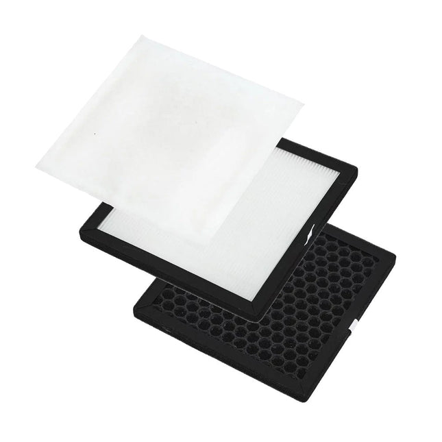
This complete replacement filter set for the Aoyue 8486 Fume Extractor contains a HEPA (High Efficiency Particulate Air) filter, a cotton air (sub) filter and an activated carbon air filter.
A modern USB-C connector makes programming easy. In addition to the pins broken out, two separate Qwiic-enabled I²C ports allow you to easily daisy chain Qwiic-enabled devices. We've exposed the SWD pins for more advanced users who prefer to use professional tools' power and speed. A USB-A connector is provided for Processor Boards that have USB Host support. A backup battery is provided for processor boards with RTC. If you need a 'lot' of GPIO with a simple-to-program, ready for the market module, the ATP is the fix you need. We've even added a convenient jumper to measure the current consumption for low power testing. Features M.2 Connector Operating Voltage Range ~3.3 V to 6.0 V (via VIN to AP7361C 3.3V Voltage Regulator) 3.3 V (via 3V3) Ports 1x USB type C 1x USB type A Host 2x Qwiic Enabled I²C 1x CAN 1x I²S 2x SPI 2x UARTs 2x Dedicated Analog Pins 2x Dedicated PWM Pins 2x Dedicated Digital Pins 12x General Purpose Input Output Pins 1x SWD 2x5 header 1 mAh battery backup for RTC Buttons Reset Boot LEDs Power 3.3 V Phillips #0 M2.5x3mm screw included
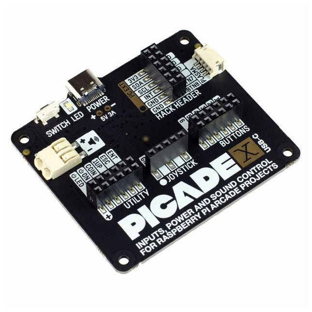
Turn your Raspberry Pi into a retro games console! Picade X HAT includes joystick and button inputs, a 3 W I²S DAC/amplifier, and soft power switch. This HAT has all the same great features as the original Picade HAT but now has no-fuss female Dupont connectors to hook up your joystick and buttons. Simply pop Picade X HAT onto your Pi, plug a USB-C power supply into the connector on the HAT (it back-powers your Pi through the GPIO, so no need for a separate power supply), wire up your controls, and install the driver! It's ideal for your own DIY arcade cabinet builds, or for interfaces that need big, colourful buttons and sound. Features I²S audio DAC with 3 W amplifier (mono) and push-fit terminals Safe power on/off system with tactile power button and LED USB-C connector for power (back-powers your Pi) 4-way digital joystick inputs 6x player button inputs 4x utility button inputs 1x soft power switch input 1x power LED output Plasma button connector Breakout pins for power, I²C, and 2 additional buttons Picade X HAT pinout Compatible with all 40-pin Raspberry Pi models The I²S DAC blends both channels of digital audio from the Raspberry Pi into a single mono output. This is then passed through a 3 W amplifier to power a connected speaker. The board also features a soft power switch that allows you turn your Pi on and off safely without risk of SD card corruption. Tap the connected button to start up, and press and hold it for 3 seconds to fully shutdown and disconnect power. Software/Installation Open a terminal and type curl https://get.pimoroni.com/picadehat | bash to run the installer. You'll need to reboot once the installation is complete, if it doesn't prompt you to do so. The software does not support Raspbian Wheezy Notes With USB-C power connected through Picade X HAT you'll need either to tap the connected power button or the button marked 'switch' on the HAT to power on your Pi.
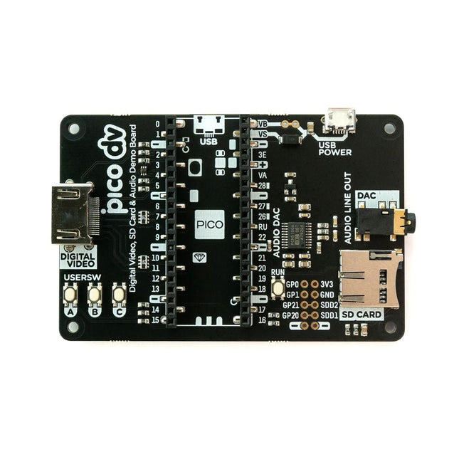
This board is an all-digital conversion of Raspberry Pi's VGA reference design, great for if you want to start hacking on video and/or audio output from a Raspberry Pi Pico and piping it straight into a modern monitor.Features
HDMI connector
PCM5100A DAC for line out audio over I²S (datasheet)
SD card slot
Reset button
Socket headers to install your Raspberry Pi Pico
Three user-controllable switches
Rubber feet
Compatible with Raspberry Pi Pico
No soldering required (as long as your Pico has header pins attached)
Programmable with C/C++
Note: Raspberry Pi Pico is not included. Your Pico will need to have pin headers soldered to it (with the pins pointing downwards) to attach to our add-on boards.Downloads
Schematic
GitHub
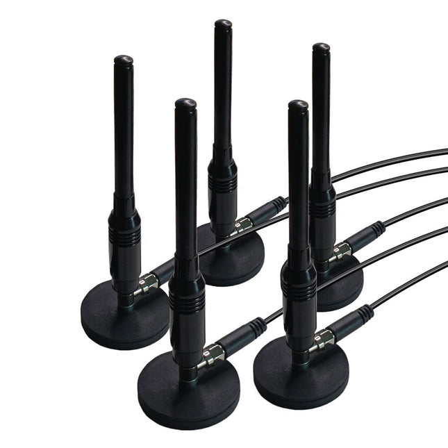
This is a set of five magnetic, telescopic whip antennas – with 100 MHz to 1 GHz tuning range – that can be used with KrakenSDR for direction finding. The magnets are strong and will be secure on the roof of a moving car. It includes a set of five two-meter, LMR100-equivalent coax cables that have been length matched for better performance.
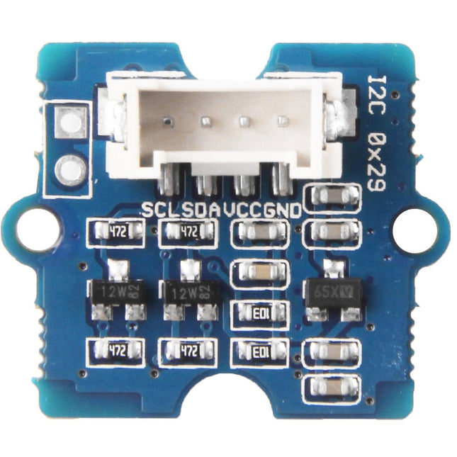
Grove - Time of Flight Distance Sensor-VL53L0X is a high speed, high accuracy and long range distance sensor based on VL53L0X. The VL53L0X is a new generation Time-of-Flight (ToF) laser-ranging module and it is one of the smallest on the market today. It provides accurate distance measurement independent of the target reflectances, making it superior to other conventional technologies. It can measure absolute distances up to 2 m, raising the standards in ranging performance levels and allowing various new applications. The VL53L0X integrates a leading-edge SPAD array (Single Photon Avalanche Diodes) and embeds ST’s second generation Flight SenseTM patented technology. The VL53L0X’s 940 nm VCSEL emitter (Vertical-Cavity Surface-Emitting Laser), is totally invisible to the human eye, coupled with internal physical infrared filters, it enables longer ranging distances, higher immunity to ambient light, and better robustness to cover glass optical crosstalk. Features VCSEL driver Ranging sensor with advanced embedded microcontroller Advanced embedded optical cross-talk compensation to simplify cover glass selection Safe for eyes: Class 1 laser device compliant with latest standard IEC 60825-1:2014 - 3rd edition Single power supply I²C interface for device control and data transfer Xshutdown (reset) and interrupt GPIO Programmable I²C address Working voltage: 3.3 V / 5 V Working temperature: 20 ℃ - 70 ℃ Recommended measurement distance: 30 mm - 1000 mm Default I²C address: 0x52 Included 1x Grove - Time of Flight Distance Sensor-VL53L0X 1x Grove Cable
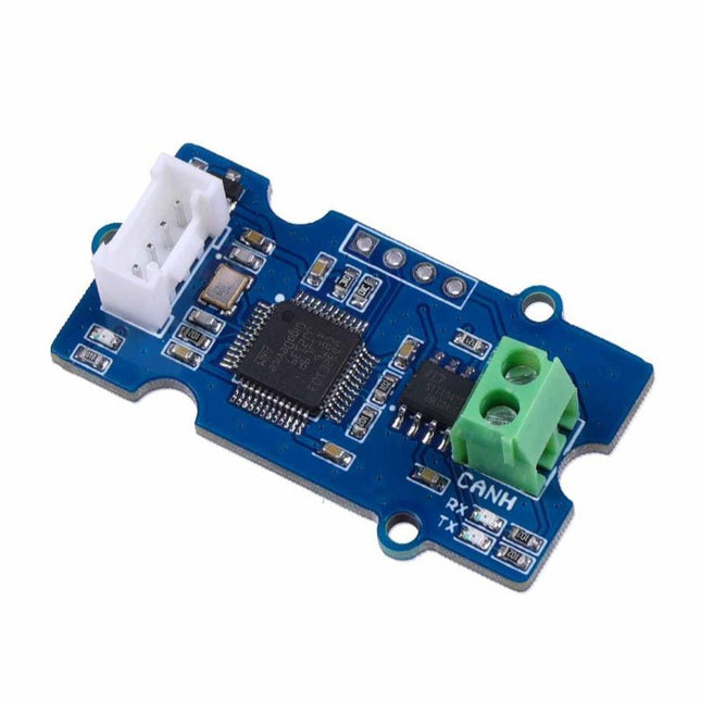
This Grove CAN-BUS Module based on GD32E103 adopts a brand-new design, uses the cost-effective and high-performance GD32E103 microcontroller as the main control and cooperates with a firmware we wrote to complete the function of the serial port to CAN FD. Features
Support CAN communication: Implements CAN FD at up to 5 Mb/s
Easy to program: Support AT command which enables simple serial port programming
Grove ecosystem: 20 x 40 x 10 mm small size, 4-pin Grove connector to plug and play, Arduino compatible This Grove CAN-BUS Module supports CAN FD(CAN with Flexible Data-Rate) communication, which is an extension to the original CAN protocol as specified in ISO 11898-1 that responds to increased bandwidth requirements in automotive networks. In CAN FD, the data rate (i.e. number of bits transmitted per second) is increased to be 5 times faster than the classic CAN (5 Mbit/s for the data payload only, the arbitration bit rate is still limited to 1Mbit/s for compatibility). It supports AT command which enables simple serial port programming. This Grove CAN-BUS Module is based on GD32E103 with a frequency up to 120 MHz. It has a flash size from 64 KB to 128 KB and an SRAM size from 20 KB to 32 KB. Applications Car hacking: allows different parts of the vehicle to talk to each other, including the engine, the transmission, and the brakes. Windows, doors, and mirror adjustment. 3D Printers Building automation Lighting control systems Medical instruments and equipment Specifications MCU GD32E103 UART baud rate Up to 115200 (default 9600) CAN FD baud rate Up to 5 Mb/s Indicator TX and RX led Working voltage 3.3 V Grove connector 4-pin Grove connector to plug and play Size 20 x 40 x 10 mm Downloads Datasheet GitHub
The Data Logging Carrier Board breaks out connections for I²C via a Qwiic connector or standard 0.1'-spaced PTH pins along with SPI and serial UART connections for logging data from peripheral devices using those communication protocols.
The Data Logging Carrier Board allows you to control power to both the Qwiic connector on the board and a dedicated 3.3 V power rail for non-Qwiic peripherals so you can pick and choose when to power the peripherals you are monitoring the data from. It also features a charging circuit for single-cell Lithium-ion batteries along with a separate RTC battery-backup circuit to maintain power to a real-time clock circuit on your Processor Board.
Features
M.2 MicroMod Connector
microSD socket
USB-C Connector
3.3 V 1 A Voltage Regulator
Qwiic Connector
Boot/Reset Buttons
RTC Backup Battery & Charge Circuit
Independent 3.3 V regulators for Qwiic bus and peripheral add-ons
Controlled by digital pins on Processor Board to enable low power sleep modes
Phillips #0 M2.5 x 3 mm screw included
This module includes an integrated trace antenna, fits the IC to an FCC-approved footprint, and includes decoupling and timing mechanisms that would need to be designed into a circuit using the bare nRF52840 IC. The Bluetooth transceiver included on the nRF52840 boasts a BT 5.1 stack. It supports Bluetooth 5, Bluetooth mesh, IEEE 802.15.4 (Zigbee & Thread) and 2.4Ghz RF wireless protocols (including Nordic's proprietary RF protocol) allowing you to pick which option works best for your application.
Features
ARM Cortex-M4 CPU with a floating-point unit (FPU)
1MB internal Flash -- For all of your program, SoftDevice, and file-storage needs!
256kB internal RAM -- For your stack and heap storage.
Integrated 2.4GHz radio with support for:
Bluetooth Low Energy (BLE) -- With peripheral and/or central BLE device support
Bluetooth 5 -- Mesh Bluetooth!
ANT -- If you want to turn the device into a heart-rate or exercise monitor.
Nordic's proprietary RF protocol -- If you want to communicate, securely, with other Nordic devices.
Every I/O peripheral you could need.
USB -- Turn your nRF52840 into a USB mass-storage device, use a CDC (USB serial) interface, and more.
UART -- Serial interfaces with support for hardware flow-control if desired.
I²C -- Everyone's favourite 2-wire bi-directional bus interface
SPI -- If you prefer the 3+-wire serial interface
Analogue-to-digital converters (ADC) -- Eight pins on the nRF52840 Mini Breakout support analogue inputs
PWM -- Timer support on any pin means PWM support for driving LEDs or servo motors.
Real-time clock (RTC) -- Keep close track of seconds and milliseconds, also supports timed deep-sleep features.
Three UARTs
Primary tied to USB interface. Two hardware UARTs.
Two I²C Buses
Two SPI Buses
Secondary SPI Bus primarily used for Flash IC.
PDM Audio Processing
Two Analog Inputs
Two Dedicated Digital I/O Pins
Two Dedicated PWM Pins
Eleven General Purpose I/O Pins
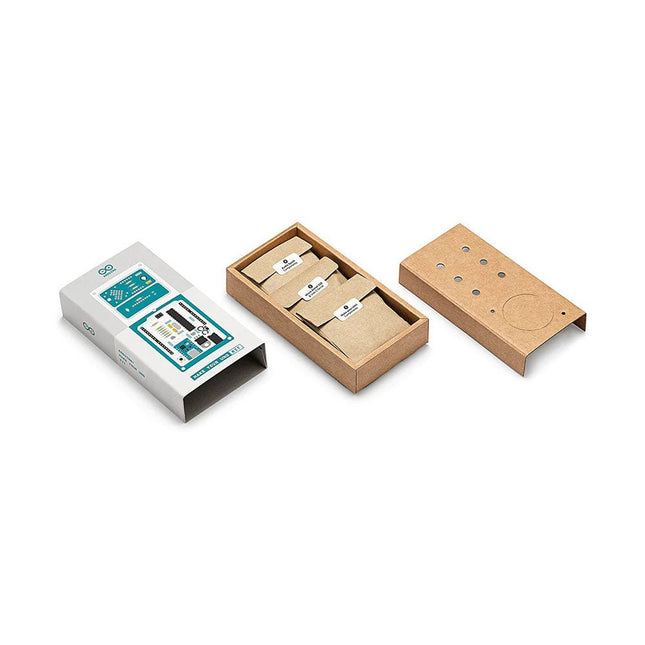
Learn the basics of electronics by assembling manually your Arduino Uno, become familiar with soldering by mounting every single component, and then unleash your creativity with the only kit that becomes a synth!
The Arduino Make-Your-Uno kit is really the best way to learn how to solder. And when you are done, the packaging allows you to build a synth and make your music.
A kit with all the components to build your very own Arduino Uno and audio synthesizer shield.
The Make-Your-Uno kit comes with a complete set of instructions in a dedicated content platform. This includes video material, a 3D interactive viewer for following detailed instructions, and how to program your board once it is finished.
This kit contains:
Arduino Make-Your-Uno
1x Make-Your-Uno PCB
1x USB C Serial adapter Board
7x Resistors 1k Ohm
2x Resistors 10k Ohm
2x Resistors 1M Ohm
1x Diode (1N4007)
1x 16 MHz Crystal
4x Yellow LEDs
1x Green LED
1x Push-Button
1x MOSFET
1x LDO (3.3 V)
1x LDO (5 V)
3x Ceramic capacitors (22pF)
3x Electrolytic capacitors (47uF)
7x Polyester capacitors (100nF)
1x Socket for ATMega 328p
2x I/O Connectors
1x Connector header 6 pins
1x Barrel jack connector
1x ATmega 328p Microcontroller
Arduino Audio Synth
1x Audio Synth PCB
1x Resistor 100k Ohm
1x Resistor 10 Ohm
1x Audio amplifier (LM386)
1x Ceramic capacitors (47nF)
1x Electrolytic capacitors (47uF)
1x Electrolytic capacitors (220uF)
1x Polyester capacitor (100nF)
4x connectors pin header
6x potentiometer 10k Ohm with plastic knobs
Spare parts
2x Electrolytic capacitors (47uF)
2x Polyester capacitor (100nF)
2x Ceramic capacitors (22pF)
1x Push-Button
1x Yellow LEDs
1x Green LED
Mechanical parts
5x Spacers 12 mm
11x Spacers 6 mm
5x screw nuts
2x screws 12 mm
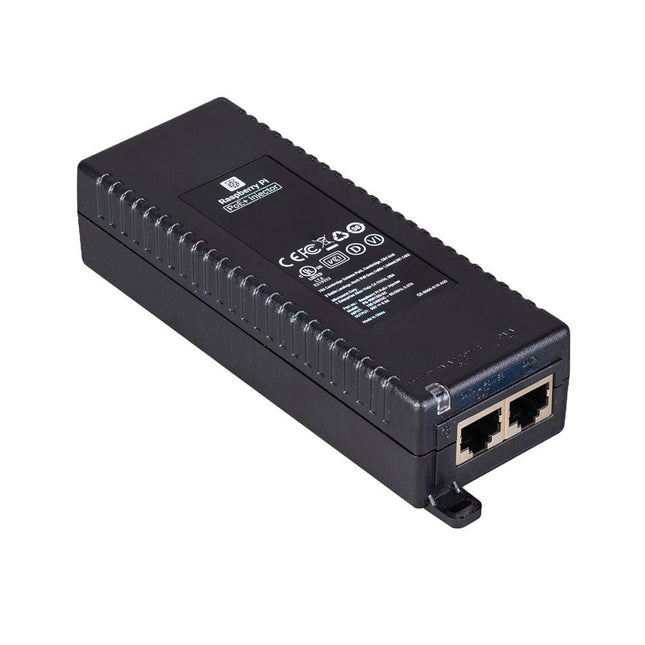
The Raspberry Pi PoE+ Injector adds Power-over-Ethernet (PoE) functionality to a single port of a non-PoE Ethernet switch, delivering both power and data through one Ethernet cable. It provides a plug-and-play, cost-effective solution for incrementally introducing PoE capability into existing Ethernet networks.
The PoE+ Injector is a single-port, 30 W device suitable for powering equipment compliant with IEEE 802.3af and 802.3at standards, including all generations of Raspberry Pi PoE HATs. It supports network pass-through speeds of 10/100/1000 Mbps.
Note: A separate IEC mains cable is required for operation (not included).
Specifications
Data rate
10/100/1000 Mbps
Input voltage
100 to 240 V AC
Output power
30 W
Power output on pins
4/5 (+), 7/8 (–)
Nominal output voltage
55 V DC
Data connectors
Shielded RJ-45, EIA 568A and 568B
Power connector
IEC c13 mains power input (not included)
Storage humidity
Maximum 95%, non-condensing
Operating altitude
–300 m to 3000 m
Operating ambient temperature
10°C to +50°C
Dimensions
159 x 51.8 x 33.5 mm
Downloads
Datasheet
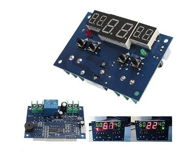
The Intelligent Digital Thermostat Temperature Controller is a small switch controller (77x51mm) which allows you to create your own thermostat. With its NTC Sensor and its LED displays, you are able to switch up to 10A 220V depending on the measured temperature.
Voice recognition, always-on voice commands, gesture, or image recognition are possible with TensorFlow applications. The cloud is impressively robust, but all-the-time connection requires power and connectivity that may not be available. Edge computing handles discrete tasks such as determining if someone said 'yes' and responds accordingly. The audio analysis is done on the MicroMod combination rather than on the web. This dramatically reduces costs and complexity while limiting potential data privacy leaks.
This board features two MEMS microphones (one with a PDM interface, one with an I²S interface), an ST LIS2DH12 3-axis accelerometer, a connector to interface to a camera (sold separately), and a Qwiic connector. A modern USB-C connector makes programming easy and we've exposed the JTAG connector for more advanced users who prefer to use the power and speed of professional tools. We've even added a convenient jumper to measure current consumption for low power testing.
Features
M.2 MicroMod Keyed-E H4.2mm 65 pins SMD Connector 0.5mm
Digital I²C MEMS Microphone PDM Invensense ICS-43434 (COMP)
Digital PDM MEMS Microphone PDM Knowles SPH0641LM4H-1 (IC)
ML414H-IV01E Lithium Battery for RTC
ST LIS2DH12TR Accelerometer (3-axis, ultra-low-power)
24 Pin 0.5mm FPC Connector (Himax camera connector)
USB-C
Qwiic connector
MicroSD socket
Phillips #0 M2.5x3mm screw included
The JOY-iT Armor Case BLOCK is a robust aluminum enclosure designed specifically for the Raspberry Pi 5. It offers excellent protection against heat and physical shocks, making it suitable for challenging environments. Its compact design ensures that it doesn't require additional space, allowing for seamless integration into existing projects.
The case includes a large heatsink to enhance cooling efficiency. Installation is straightforward, with four screws (included) securing the case to the Raspberry Pi.
Specifications
Material
CNC milled aluminum alloy
Cooling performance
Idle: ~39°CFull load: ~75°C
Special features
Large heat sink, protection against shocks and heat with the same volume as without housing
Dimensions (top side)
69 x 56 x 15,5 mm
Dimensions (bottom side)
87 x 56 x 7,5 mm