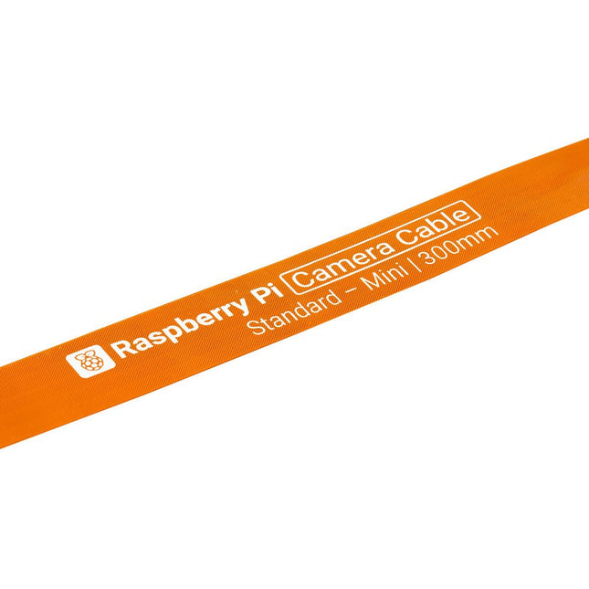
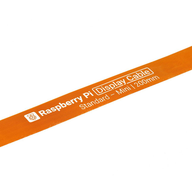
Raspberry Pi 5 provides two four-lane MIPI connectors, each of which can support either a camera or a display. These connectors use the same 22-way, 0.5 mm-pitch “mini” FPC format as the Compute Module Development Kit, and require adapter cables to connect to the 15-way, 1 mm-pitch “standard” format connectors on current Raspbery Pi camera and display products.These mini-to-standard adapter cables for cameras and displays (note that a camera cable should not be used with a display, and vice versa) are available in 200 mm, 300 mm and 500 mm lengths.
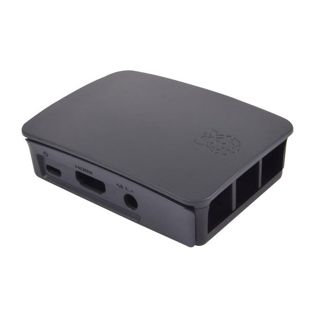
High-quality ABS construction Removable side panels and lid for easy access to GPIO, camera and display connectors Light pipes for power and activity LEDs Extraordinarily handsome Colour: black/grey
Features Build in USB to Serial interface Build-in PCB antenna Powered by Pineseed BL602 SoC using Pinenut model: 12S stamp 2 MB Flash USB-C connection Suitable to breadboard BIY project On board three color LEDs output Dimensions: 25.4 x 44.0 mm Note: USB cable is not included.
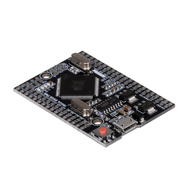
This JOY-iT microcontroller board opens the world of programming to you and offers you the same computing power as the Mega 2560, but with a smaller foot-print. It also has many more connectors than comparable boards (Arduino Uno). It is powered by the Arduino IDE and power can be supplied either via the USB port or the VIN pins. This allows you to use it safely with many other devices, e.g. desktop PC. Therefore the Mega 2560 Pro is highly integrable.
Features
Microcontroller
ATmega2560 - 16AU
Storage
Flash 256 KB, SRAM 8 KB, EEPRom 4 KB
Amount of Pins:Digital I/OPWM OutputAnalog Input
541516
Compatible with
Arduino, Desktop PCs, etc.
Special features
USB Port or Power Pins for power supply
Interface converter
Micro USB to USB UART
Size
55 x 38 mm
Items delivered
JOY-iT Mega 2560 Pro with Pins
Further Specifications
Input Voltage
7 - 9 Volt on Vin, 5 Volt on mUSB
Logic level
5 Volt
Output current
800 mA
Voltage regulator
LDO (for up to 12 V peak)
Frequency
16 MHz (12 MHz are possible for data exchange)
Downloads
Manual
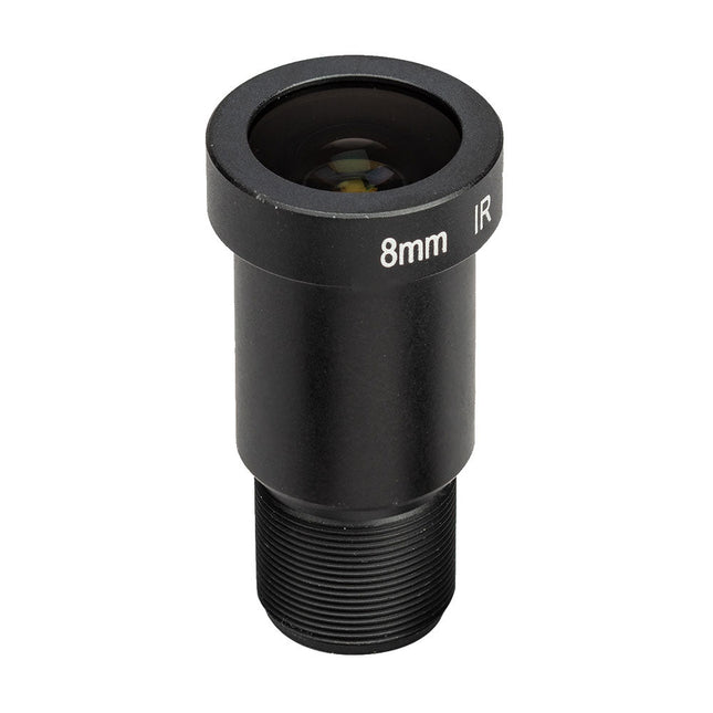
The M12 Mount Lens (12 MP, 8 mm) is ideal for use with the Raspberry Pi HQ Camera Module, offering sharp and detailed imaging for a wide range of applications.
This rugged, passive aluminum cooling case is made specifically for the Raspberry Pi 5 and offers a sleek design that ensures both durability and effective heat dissipation. The case is exclusively compatible with the Raspberry Pi 5 and provides a passive cooling solution, eliminating the need for a fan while still managing heat efficiently.
Features
High quality aluminum construction: Made from high quality aluminum, this case is built to last and withstand regular use.
Optimized heat dissipation: The passive cooling design uses the aluminum structure to keep your Raspberry Pi 5 cool without the need for a fan.
Full port accessibility: Every port on the Raspberry Pi 5 is easily accessible, from the microSD card slot to USB, micro HDMI and GPIO ports.
GPIO cable support: A reserved interface for the GPIO cable ensures that you can continue to use this important function without having to remove the case.
Convenient power switch: The case has an integrated power switch that allows you to turn your device on and off.
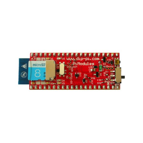
The DiP-Pi PIoT is an Advanced Powered, WiFi connectivity System with sensors embedded interfaces that cover most of possible needs for IoT application based on Raspberry Pi Pico. It can supply the system with up to 1.5 A @ 4.8 V delivered from 6-18 VDC on various powering schemes like Cars, Industrial plant etc., additionally to original micro-USB of the Raspberry Pi Pico. It supports LiPo or Li-Ion Battery with Automatic Charger as also automatic switching from cable powering to battery powering or reverse (UPS functionality) when cable powering lost. Extended Powering Source (EPR) is protected with PPTC Resettable fuse, Reverse Polarity, as also ESD.
The DiP-Pi PIoT contains Raspberry Pi Pico embedded RESET button as also ON/OFF Slide Switch that is acting on all powering sources (USB, EPR or Battery). User can monitor (via Raspberry Pi Pico A/D pins) battery level and EPR Level with PICO’s A/D converters. Both A/D inputs are bridged with 0402 resistors (0 OHM) therefore if for any reason user needs to use those Pico pins for their own application can be easy removed. The charger is automatically charging connected battery (if used) but in addition user can switch charger ON/OFF if their application needs it.
DiP-Pi PIoT can be used for cable powered IoT systems, but also for pure Battery Powered System with ON/OFF. Each powering source status is indicated by separate informative LEDs (VBUS, VSYS, VEPR, CHGR, V3V3).
User can use any capacity of LiPo or Li-Ion type; however, must take care to use PCB protected batteries with max discharge current allowed of 2 A. The embedded battery charger is set to charge battery with 240 mA current. This current is set by resistor so if user need more/less can himself to change it. The DiP-Pi PIoT is also equipped with WiFi ESP8266 Clone module with embedded antenna. This feature open a wide range of IoT applications based on it.
In Addition to all above features DiP-Pi PIoT is equipped with embedded 1-wire, DHT11/22 sensors, and micro–SD Card interfaces. Combination of the extended powering, battery, and sensors interfaces make the DiP-Pi PIoT ideal for IoT applications like data logger, plants monitoring, refrigerators monitoring etc.
DiP-Pi PIoT is supported with plenty of ready to use examples written in Micro Python or C/C++.
Specifications
General
Dimensions 21 x 51 mm
Raspberry Pi Pico pinout compatible
Independent Informative LEDs (VBUS, VSYS, VEPR, CHGR, V3V3)
Raspberry Pi Pico RESET Button
ON/OFF Slide Switch acting on all powering sources (USB, EPR, Battery)
External Powering 6-18 VDC (Cars, Industrial Applications etc.)
External Power (6-18 VDC) Level Monitoring
Battery Level Monitoring
Inverse Polarity Protection
PPTC Fuse Protection
ESD Protection
Automatic Battery Charger (for PCB protected LiPo, Li-Ion – 2 A Max) Automatic/User Control
Automatic Switch from Cable Powering to Battery Powering and reverse (UPS Functionality)
Various powering schemes can be used at the same time with USB Powering, External Powering and Battery Powering
1.5 A @ 4.8 V Buck Converter on EPR
Embedded 3.3 V @ 600 mA LDO
ESP8266 Clone WiFi Connectivity
ESP8266 Firmware Upload Switch
Embedded 1-wire Interface
Embedded DHT-11/22 Interface
Powering Options
Raspberry Pi Pico micro-USB (via VBUS)
External Powering 6-18 V (via dedicated Socket – 3.4/1.3 mm)
External Battery
Supported Battery Types
LiPo with protection PCB max current 2A
Li-Ion with protection PCB max current 2A
Embedded Peripherals and Interfaces
Embedded 1-wire interface
Embedded DHT-11/22 Interface
Micro SD Card Socket
Programmer Interface
Standard Raspberry Pi Pico C/C++
Standard Raspberry Pi Pico Micro Python
Case Compatibility
DiP-Pi Plexi-Cut Case
System Monitoring
Battery Level via Raspberry Pi Pico ADC0 (GP26)
EPR Level via Raspberry Pi Pico ADC1 (GP27)
Informative LEDs
VB (VUSB)
VS (VSYS)
VE (VEPR)
CH (VCHR)
V3 (V3V3)
System Protection
Direct Raspberry Pi Pico Hardware Reset Button
ESD Protection on EPR
Reverse Polarity Protection on EPR
PPTC 500 mA @ 18 V fuse on EPR
EPR/LDO Over Temperature protection
EPR/LDO Over Current protection
System Design
Designed and Simulated with PDA Analyzer with one of the most advanced CAD/CAM Tools – Altium Designer
Industrial Originated
PCB Construction
2 ozcopper PCB manufactured for proper high current supply and cooling
6 mils track/6 mils gap technology 2 layers PCB
PCB Surface Finishing – Immersion Gold
Multi-layer Copper Thermal Pipes for increased System Thermal Response and better passive cooling
Downloads
Datasheet
Manual
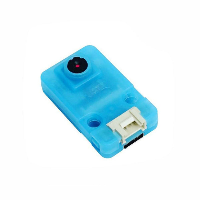
OV7740 is a AI Camera powered by Kendryte K210, an edge computing system-on-chip(SoC) with a dual-core 64bit RISC-V CPU and state-of-art neural network processor.
Features
Dual-Core 64-bit RISC-V RV64IMAFDC (RV64GC) CPU / 400Mhz(Normal)
Dual Independent Double Precision FPU
8MiB 64bit width On-Chip SRAM
Neural Network Processor(KPU) / 0.8Tops
Field-Programmable IO Array (FPIOA)
AES, SHA256 Accelerator
Direct Memory Access Controller (DMAC)
Micropython Support
Firmware encryption support
On-board Hardware:
Flash: 16M Camera :OV7740
2x Buttons
Status Indicator LED
External storage: TF card/Micro SD
Interface: HY2.0/compatible GROVE
Applications
Face recognition/detection
Object detection/classification
Obtain the size and coordinates of the target in real-time
Obtain the type of detected target in real-time
Shape recognition Video recorder
Included
1x UNIT-V(include 20cm 4P cable and USB-C cable)
With a 6x20 grid of 2.54 mm spaced holes for easy soldering and labelled Pico pins so you know what's what, Pico Proto is perfect for when you're happy with your breadboard project and want to give it a secure, smart and compact long-term home.
Pico Proto doesn't come with any headers attached, so you will need to either solder it directly to your Pico's male header pins (for a permanent, but super slim sandwich) or solder it to some female header.
Features
40 2.54 mm spaced holes for attaching to your Pico.
120 2.54 mm spaced holes (6x20 grid) for attaching other things
Compatible with Raspberry Pi Pico.
Dimensions: approx 51 x 25 x 1 mm (L x W x H)
Raspberry Pi 5 provides two four-lane MIPI connectors, each of which can support either a camera or a display. These connectors use the same 22-way, 0.5 mm-pitch “mini” FPC format as the Compute Module Development Kit, and require adapter cables to connect to the 15-way, 1 mm-pitch “standard” format connectors on current Raspbery Pi camera and display products.These mini-to-standard adapter cables for cameras and displays (note that a camera cable should not be used with a display, and vice versa) are available in 200 mm, 300 mm and 500 mm lengths.
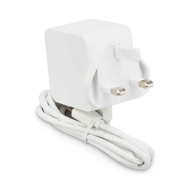
The Raspberry Pi 27 W PD USB-C power supply is designed specifically to power the Raspberry Pi 5. It is also capable of delivering 5 V/3 A, 9 V/3 A, 12 V/2.25 A, 15 V/1.8 A to PD-compatible products, making it a good and cost-effective power supply for many general applications, such as charging smartphones and tablets.
Specifications
Input
100-240 V AC
Output
5 A @ 5.1 V, 3 A @ 9 V, 2.25 A @ 12 V, 1.8 A @ 15 V
Connector
USB-C
Length
1.2 m
Color
White
Region
UK
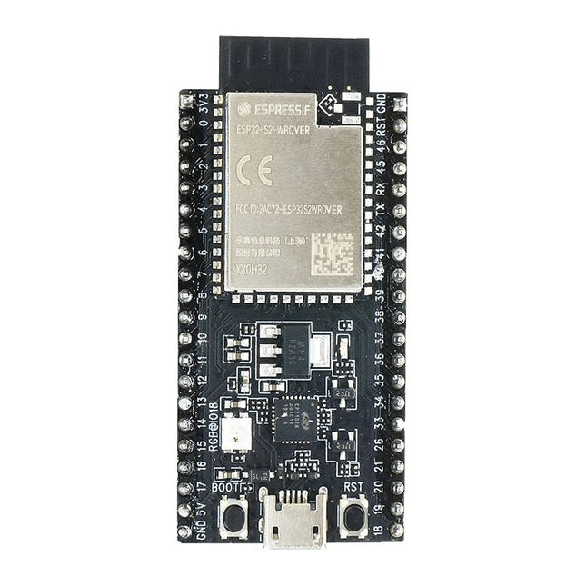
ESP32-S2-Saola-1R is a small-sized ESP32-S2 based development board. Most of the I/O pins are broken out to the pin headers on both sides for easy interfacing. Developers can either connect peripherals with jumper wires or mount ESP32-S2-Saola-1R on a breadboard.ESP32-S2-Saola-1R is equipped with the ESP32-S2-WROVER module, a powerful, generic Wi-Fi MCU module that has a rich set of peripherals. It is an ideal choice for a wide variety of application scenarios relating to Internet of Things (IoT), wearable electronics and smart home. The board a PCB antenna and features a 4 MB external SPI flash and an additional 2 MB SPI Pseudo static RAM (PSRAM).FeaturesMCU
ESP32-S2 embedded, Xtensa® single-core 32-bit LX7 microprocessor, up to 240 MHz
128 KB ROM
320 KB SRAM
16 KB SRAM in RTC
WiFi
802.11 b/g/n
Bit rate: 802.11n up to 150 Mbps
A-MPDU and A-MSDU aggregation
0.4 µs guard interval support
Center frequency range of operating channel: 2412 ~ 2484 MHz
Hardware
Interfaces: GPIO, SPI, LCD, UART, I²C, I²S, Camera interface, IR, pulse counter, LED PWM, TWAI (compatible with ISO 11898-1), USB OTG 1.1, ADC, DAC, touch sensor, temperature sensor
40 MHz crystal oscillator
4 MB SPI flash
Operating voltage/Power supply: 3.0 ~ 3.6 V
Operating temperature range: –40 ~ 85 °C
Dimensions: 18 × 31 × 3.3 mm
Applications
Generic Low-power IoT Sensor Hub
Generic Low-power IoT Data Loggers
Cameras for Video Streaming
Over-the-top (OTT) Devices
USB Devices
Speech Recognition
Image Recognition
Mesh Network
Home Automation
Smart Home Control Panel
Smart Building
Industrial Automation
Smart Agriculture
Audio Applications
Health Care Applications
Wi-Fi-enabled Toys
Wearable Electronics
Retail & Catering Applications
Smart POS Machines
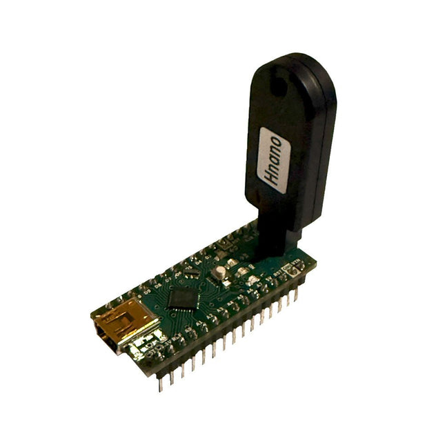
This programmer is specifically designed for burning bootloaders (without a computer) on Arduino-compatible ATmega328 development boards.
Simply plug the programmer into the ICSP interface to re-burn the bootloader. It’s also compatible with new chips, provided the IC is functional.
Note: Burning a bootloader erases all previous chip data.
Features
Working voltage: 3.1-5.3 V
Working current: 10 mA
Compatible with Arduino Nano based boards (ATmega328)
Dimensions: 39.6 x 15.5 x 7.8 mm
The Speaker Kit for Raspberry Pi is a small amplified speaker designed for the Raspberry Pi.
Included
MonkMakes Amplified Speaker
Set of 10 female to female header wires
Short stereo audio lead
Raspberry Leaf GPIO template
Downloads
Instructions
Datasheet
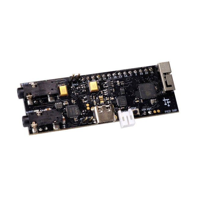
PÚCA DSP is an open-source, Arduino-compatible ESP32 development board for audio and digital signal processing (DSP) applications with expansive audio-processing features. It provides audio inputs, audio outputs, a low-noise microphone array, an integrated test-speaker option, additional memory, battery-charge management, and ESD protection all on a small, breadboard-friendly PCB.
Synthesizers, Installations, Voice UI, and More
PÚCA DSP can be used for a wide range of DSP applications, including but not limited to those in the fields of music, art, creative technology, and adaptive technology. Music-related examples include digital-music synthesis, mobile recording, Bluetooth speakers, wireless line-level directional microphones, and the design of smart musical instruments. Art-related examples include acoustic sensor networks, sound-art installations, and Internet-radio applications. Examples related to creative and adaptive technology include voice user interface (VUI) design and Web audio for the Internet of Sounds.
Compact, Integrated Design
PÚCA DSP was designed for portability. When used with an external 3.7 V rechargeable battery, it can be deployed almost anywhere or integrated into just about any device, instrument, or installation. Its design emerged from months of experimentation with various ESP32 development boards, DAC breakout boards, ADC breakout boards, Microphone breakout boards, and audio-connector breakout boards, and – despite its diminutive size – it manages to provide all of that functionality in a single board. And it dos so without compromising signal quality.
Specifications
Processor & Memory
Espressif ESP32 Pico D4 Processor
32-bit dual core 80 MHz / 160 MHz / 240 MHz
4 MB SPI Flash with 8 MB additional PSRAM (Original Edition)
Wireless 2.4 GHz Wi-Fi 802.11b/g/n
Bluetooth BLE 4.2
3D Antenna
Audio
Wolfson WM8978 Stereo Audio Codec
Audio Line In on 3.5 mm stereo onnector
Audio Headphone / Line Out on 3.5 mm stereo connector
Stereo Aux Line In, Audio Mono Out routed to GPIO Header
2x Knowles SPM0687LR5H-1 MEMS Microphones
ESD protection on all audio inputs and outputs
Support for 8, 11.025, 12, 16, 22.05, 24, 32, 44.1 and 48 kHz sample rates
1 W Speaker Driver, routed to GPIO Header
DAC SNR 98 dB, THD -84 dB (‘A’ weighted @ 48 kHz)
ADC SNR 95 dB, THD -84 dB (‘A’ weighted @ 48 kHz)
Line input impedance: 1 MOhm
Line output impedance: 33 Ohm
Form Factor and Connectivity
Breadboard friendly
70 x 24 mm
11x GPIO pins broken out to 2.54 mm pitch header, with access to both ESP32 ADC channels, JTAG and capacitive touch pins
USB 2.0 over USB Type C connector
Power
3.7/4.2 V Lithium Polymer Rechargeable Battery, USB or external 5 V DC power source
ESP32 and Audio Codec can be placed into low power modes under software control
Battery voltage level detection
ESD protection on USB data bus
Downloads
GitHub
Datasheet
Links
Crowd Supply Campaign (includes FAQs)
Hardware Overview
Programming the Board
The Audio Codec
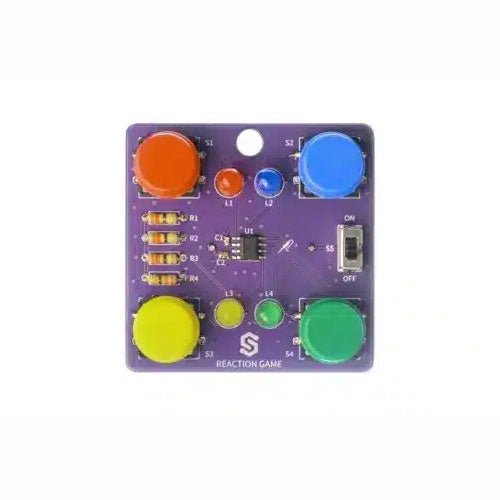
If you are looking for a simple way to learn soldering, or just want to make a small gadget that you can carry, this set is a great opportunity. Reaction game is an educational kit which teaches you how to solder, and in the end, you get to have your own small game. The goal of the game is to press the button next to the LED as soon as it turns on. With every correct answer, the game gets a bit harder – the time you have to press the button shortens. How many correct answers can you get?
It’s based on ATtiny404 microcontroller, programmed in Arduino. At its back, you’ll find CR2032 battery which makes the kit portable. There’s keychain holder as well. Soldering process is easy enough based on the mark on the PCB.
Included
1x PCB
1x ATtiny404 microcontroller
4x LEDs
4x Pushbuttons
1x Switch
4x Resistors (330 ohm)
1x CR2032 battery holder
1x Battery CR2032
1x Keychain holder
The Maker pHAT is the solution to the most common problems beginners face starting with Raspberry PI. Its intelligent and simple design makes it easy to attach to your Pi, and it helps you avoid all the tedious work of connection various other accessories. Additionally, the LEDs corresponding to each pin makes it extremely easy to see where a potential problem lies
The Maker pHat has the same size as the Raspberry Pi Zero with all 4mounting holes aligned. However, it can be used with Raspberry Pi 3B, 3B+ and 3A+, by inserting a 2 x 20 stacking header.
Features
Raspberry Pi Zero size, stack perfectly on to Raspberry Pi Zero
Compatible with standard size Raspberry Pi 3B / 3B+, medium size Raspberry Pi 3A+ and smaller size Raspberry Pi Zero / W / WH.
Standard Raspberry Pi GPIO footprint.
LED array for selected GPIO pins (GPIO 17, 18, 27, 22, 25, 12, 13, 19).
3x on board programmable push buttons (GPIO 21, 19 and 20, need to configure as input pull up).
Onboard active buzzer (GPIO 26).
Proper labels for all GPIOs, including SPI, UART, I2C, 5V, 3.3V, and GND.
Utilize USB Micro-B socket for 5V input and USB to UART communication.
USB serial facilitated by the FT231X
Input voltage: USB 5 V, from a computer, power bank or a standard USB adapter.
The SparkFun GPS-RTK2 raises the bar for high-precision GPS and is the latest in a line of powerful RTK boards featuring the ZED-F9P module from u-blox. The ZED-F9P is a top-of-the-line module for high accuracy GNSS and GPS location solutions, including RTK capable of 10 mm, three-dimensional accuracy. With this board, you will be able to know where your (or any object's) X, Y, and Z location is within roughly the width of your fingernail! The ZED-F9P is unique in that it is capable of both rover and base station operations. Utilizing our handy Qwiic system, no soldering is required to connect it to the rest of your system. However, we still have broken out 0.1"-spaced pins if you prefer to use a breadboard.
We've even included a rechargeable backup battery to keep the latest module configuration and satellite data available for up to two weeks. This battery helps 'warm-start' the module decreasing the time-to-first-fix dramatically. This module features a survey-in mode allowing the module to become a base station and produce RTCM 3.x correction data.
The number of configuration options of the ZED-F9P is incredible! Geofencing, variable I²C address, variable update rates, even the high precision RTK solution can be increased to 20 Hz. The GPS-RTK2 even has five communications ports which are all active simultaneously: USB-C (which enumerates as a COM port), UART1 (with 3.3 V TTL), UART2 for RTCM reception (with 3.3V TTL), I²C (via the two Qwiic connectors or broken out pins), and SPI.
Sparkfun has also written an extensive Arduino library for u-blox modules to easily read and control the GPS-RTK2 over the Qwiic Connect System. Leave NMEA behind! Start using a much lighter weight binary interface and give your microcontroller (and its one serial port) a break. The SparkFun Arduino library shows how to read latitude, longitude, even heading and speed over I²C without the need for constant serial polling.
Features
Concurrent reception of GPS, GLONASS, Galileo and BeiDou
Receives both L1C/A and L2C bands
Voltage: 5 V or 3.3 V, but all logic is 3.3 V
Current: 68 mA - 130 mA (varies with constellations and tracking state)
Time to First Fix: 25 s (cold), 2 s (hot)
Max Navigation Rate:
PVT (basic location over UBX binary protocol) - 25 Hz
RTK - 20 Hz
Raw - 25 Hz
Horizontal Position Accuracy:
2.5 m without RTK
0.010 m with RTK
Max Altitude: 50k m
Max Velocity: 500 m/s
2x Qwiic Connectors
Dimensions: 43.5 x 43.2 mm
Weight: 6.8 g
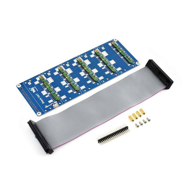
This is an I/O expansion kit designed for Raspberry Pi, which provides 5 sets of 2x20 pinheaders, that means a handy way to 'stack' multi different HATs together, and use them as a specific combination / project.
Features
Standard Raspberry Pi connectivity, directly pluggable OR through ribbon cable
5 sets of 2x20 pinheaders, connect multi HATs together
USB external power port, provides enough power supply for multi HATs
Clear and descriptive pin labels for easy use
Reserved jumper pads on the bottom side, pin connections are changeable by soldering, to avoid pin conflicts
Note: make sure there are no any pin conflicts between the HATs you want to use together before connecting.
Specifications
Dimensions: 183 × 65 mm
Mounting hole size: 3 mm
Included
1x Stack HAT
1x Ribbon cable 40-Pin
1x 2x20 male pinheader
1x RPi screws pack (4pcs) x1
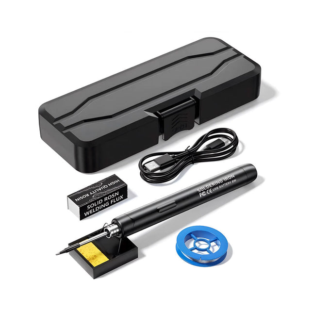
The Smart USB Soldering Iron Kit is a compact, cordless solution designed for precision and portability. Featuring intelligent three-speed temperature control (300-450°C) with an easy-to-read LED display, it heats up in just 10 seconds and melts solder in as little as 6 seconds.
The 1000 mAh rechargeable battery delivers up to 30 minutes of continuous use, making it ideal for quick repairs, electronics projects, and DIY tasks. With a plug-and-play, replaceable tip and a high-temperature-resistant insulated shell, it’s safe, user-friendly, and perfect for both beginners and professionals on the go.
Features
Three-Speed Intelligent Temperature Adjustment: Features an LED display screen with adjustable temperatures between 300-450°C (572-842°F). Easily switch between Celsius and Fahrenheit.
Integrated Plug-In Soldering Iron Tip: Plug-and-play design. The tip can be replaced by simply unscrewing it, ensuring quick and convenient operation.
Safe and Durable Design: High-temperature-resistant, insulated shell for enhanced safety during use.
Battery Capacity: Equipped with a rechargeable 1000 mAh battery that supports up to 30 minutes of continuous operation on a full charge – ideal for everyday tasks.
Efficient Performance: 8 W power with an integrated heating core for rapid heat-up. Melts tin in just 6 seconds, providing excellent thermal conductivity.
Easy to Use: After powering on via USB, set your desired temperature. The soldering iron heats up in 10 seconds. Once finished, place the tip on the stand—it cools down within 1 minute. Perfect for beginners, hobbyists, basic home repairs, and training engineers.
Cordless Innovation: This cordless soldering kit includes a built-in rechargeable lithium-ion battery, eliminating the need for cables. Versatile use for circuit board soldering, electrical repairs, jewelry making, metal crafts, computer maintenance, and DIY projects.
Specifications
Adjustable Temperature: 300-450°C (572-842°F)
Tin Melting Time: <15 seconds
Working Voltage: 5 V
Power Output: 8 W
Battery Capacity: 1000 mAh
Auto Sleep Function: Activates after 10 minutes of inactivity
Charging Time: Approx. 90 minutes
Battery Life: Up to 30 minutes continuous use
Charging Interface: USB-C
Main Material: Aluminum alloy
Dimensions: 190 x 16 mm (7.4 x 0.6")
Included
1x USB Soldering Iron
1x Soldering Tip
1x Soldering Rosin
1x Soldering Iron Holder (with Sponge)
1x USB-C Charging Cable
1x Solder Wire
1x Storage Box
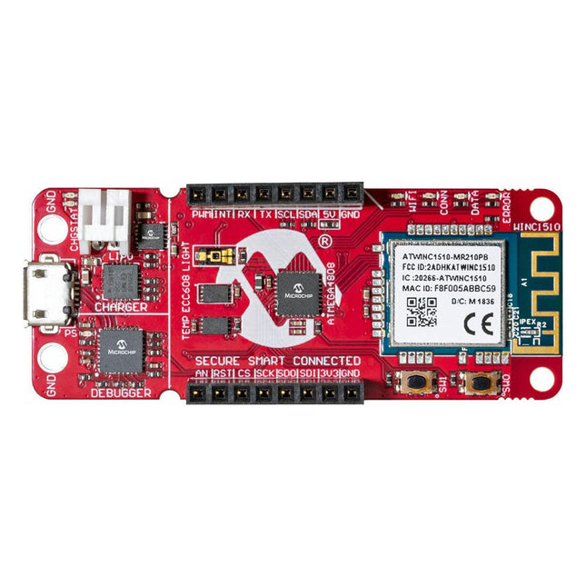
The AVR-IoT WA development board combines a powerful ATmega4808 AVR MCU, an ATECC608A CryptoAuthentication secure element IC and the fully certified ATWINC1510 Wi-Fi network controller – which provides the most simple and effective way to connect your embedded application to Amazon Web Services (AWS). The board also includes an on-board debugger, and requires no external hardware to program and debug the MCU.
Out of the box, the MCU comes preloaded with a firmware image that enables you to quickly connect and send data to the AWS platform using the on-board temperature and light sensors. Once you are ready to build your own custom design, you can easily generate code using the free software libraries in Atmel START or MPLAB Code Configurator (MCC).
The AVR-IoT WA board is supported by two award-winning Integrated Development Environments (IDEs) – Atmel Studio and Microchip MPLAB X IDE – giving you the freedom to innovate with your environment of choice.
Features
ATmega4808 microcontroller
Four user LED’s
Two mechanical buttons
mikroBUS header footprint
TEMT6000 Light sensor
MCP9808 Temperature sensor
ATECC608A CryptoAuthentication™ device
WINC1510 WiFi Module
On-board Debugger
Auto-ID for board identification in Atmel Studio and Microchip MPLAB X
One green board power and status LED
Programming and debugging
Virtual COM port (CDC)
Two DGI GPIO lines
USB and battery powered
Integrated Li-Ion/LiPo battery charger
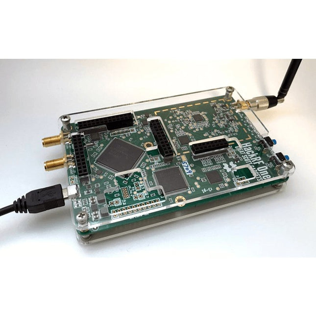
This clear acrylic case is the official case for the HackRF One board. It can replace the standard black plastic case of the HackRF One.
Assembly Instructions
Use a guitar pick or spudger to extract the HackRF One circuit board from the black plastic case.
Insert one long screw into each corner of the bottom acrylic panel. Secure each long screw with a short (5 mm) spacer on the opposite side of the panel.
Place the HackRF One circuit board (facing up) on top of the bottom panel, fitting the ends of the long screws through the corner mounting holes of the circuit board.
Secure the circuit board with one long (6 mm) spacer in each corner.
Place the top acrylic panel on top of the circuit board, aligning the cutouts with the circuit board’s expansion headers.
Secure each corner with a short screw.
Note: Do not overtighten! Hand-tighten only at every step.
Specifications
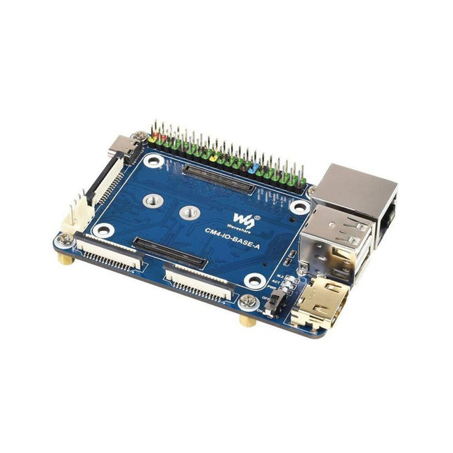
CM4 socket
Suitable for all variants of Compute Module 4
Networking
Gigabit Ethernet RJ45 connectorM.2 M KEY, supports communication modules or NVME SSD
Connector
Raspberry Pi 40-PIN GPIO header
USB
2x USB 2.0 Type A2x USB 2.0 via FFC connector
Display
MIPI DSI display port (15-pin 1.0 mm FPC connector)
Camera
2x MIPI CSI-2 camera port (15-pin 1.0 mm FPC connector)
Video
2x HDMI port (including one port via FFC connector), supports 4K 30fps output
RTC
N/A
Storage
MicroSD card socket for Compute Module 4 Lite (without eMMC) variants
Fan header
No fan control, 5 V
Power input
5 V
Dimensions
85 x 56 mm
Included
1x CM4-IO-BASE-A
1x SSD mounting screw
Downloads
Wiki