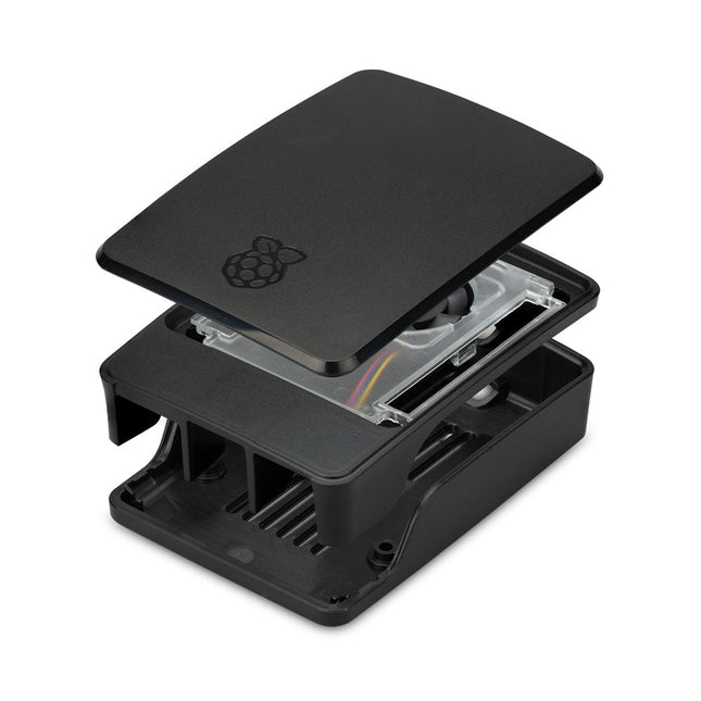
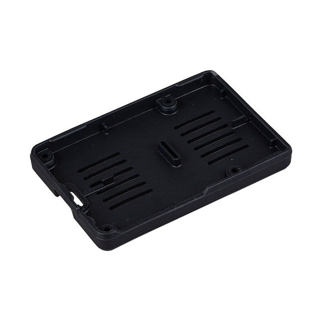
The Raspberry Pi 5 case is a refinement of the Raspberry Pi 4 case with improved thermal features to support the higher peak power consumption of the Raspberry Pi 5. It integrates a variable speed fan that is powered and controlled via a dedicated connector on the Raspberry Pi 5.
This USB Stick contains more than 300 Arduino-related articles published in Elektor Magazine. The content includes both background articles and projects on the following topics:
Software & hardware development: Tutorials on Arduino software development using Arduino IDE, Atmel Studio, Shields, and essential programming concepts.
Learning: The Microcontroller Bootcamp offers a structured approach to programming embedded systems.
Data acquisition & measurement: Projects such as a 16-bit data logger, lathe tachometer, and an AC grid analyzer for capturing and analyzing real-time signals.
Wireless communication: Learn how to implement wireless networks, create an Android interface, and communicate effectively with microcontrollers.
Robotics and automation: This covers the Arduino Nano Robot Controller, supporting boards for automation, and explores various Arduino shields to enhance functionality.
Self-build projects: Unique projects such as laser projection, Numitron clock and thermometer, ELF receiver, Theremino, and touch LED interfaces highlight creative applications.
Whether you're a beginner or an experienced maker, this collection is a valuable resource for learning, experimenting, and pushing the boundaries of Arduino technology.
The Raspberry Pi M.2 HAT+ enables you to connect M.2 peripherals such as NVMe drives and AI accelerators to Raspberry Pi 5’s PCIe 2.0 interface, supporting fast (up to 500 MB/s) data transfer to and from NVMe drives and other PCIe accessories.
Raspberry Pi M.2 HAT+ supports devices that have the M.2 M key edge connector, in the 2230 and 2242 form factors. It is capable of supplying up to 3 A to connected M.2 devices.
Features
Supports single-lane PCIe 2.0 interface (500 MB/s peak transfer rate)
Supports devices that use the M.2 M key edge connector
Supports devices with the 2230 or 2242 form factor
Capable of supplying up to 3 A to connected M.2 devices
Power and activity LEDs
Included
1x Raspberry Pi 5 M.2 HAT+
1x Ribbon cable
1x GPIO stacking header
4x Spacers
8x Screws
Downloads
Datasheet
Schematics
Assembly instructions
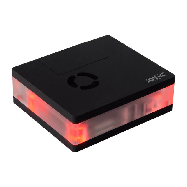
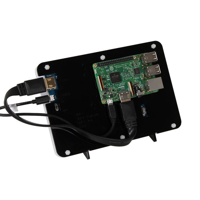
This multimedia case for all Raspberry Pi 4 models is characterized by high functionality, modern design and a sumptuous equipment:
Integrated IR receiver, controllable with almost all IR remote controls
Controllable LED lighting
Switching on/off, controlling additional functions of the Raspberry Pi
Active, quiet cooling
Toolless, magnetic assembly
All connections of the Raspberry Pi are on the backside
GPIO port is accessible via separate lid
Perfect as a multimedia platform in the living room, desktop device or for the use in digital signage.
Specifications
Material
Acryl
Color
Black
Compatible to
Raspberry Pi 4
Power supply
5 VDC (USB-C)
Microcontroller
STM32F030F4P
Infrared receiver
TSOP4838
LEDs
4x WS2812Mini
Led out connections
1x USB-C, 1x Aux, 2x microHDMIFrom Raspberry Pi: 2x USB-A 3.0, 2x USB-A 2.0, 1x RJ45
Weight
280 g
Dimensions
113 x 100 x 38 mm
Scope of delivery
Multimedia case, adapter board, control board, Aux adapter cable
Downloads
Datasheet (177.9 KB)
Manual (3.5 MB)
Expert Guide (6.5 MB)
Firmware v1.0.9-beta (11.2 KB)
Addons for LibreElec 9 (2.6 MB)
Code Examples
Addon - Multimedia Case Configuration
Addon - LED Configuration
Addon - IR Control Configuration
Prepared LibreElec Image
Prepared LibreElec Image 10.BETA
GitHub
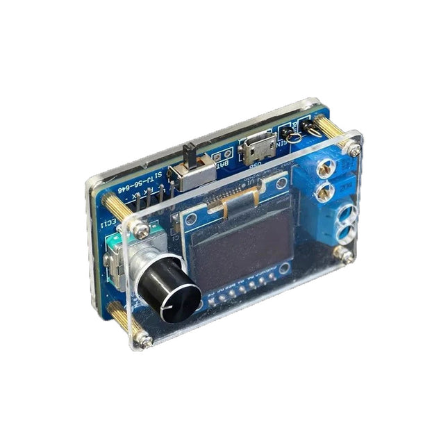
The DIY Mini Digital Oscilloscope Kit (with shell) is an easy-to-build kit for a tiny digital oscilloscope. Besides the power switch, it has only one other control, a rotary encoder with a built-in pushbutton. The kit's microcontroller comes preprogrammed. The 0.96" OLED display has a resolution of 128 x 64 pixels. The oscilloscope features one channel that can measure signals up to 100 kHz. The maximum input voltage is 30 V, the minimum voltage is 0 V.
The kit consists of through-hole components (THT) are surface-mount devices (SMD). Therefore, assembling the kit means soldering SMD parts, which requires some soldering experience.
Specifications
Vertical range: 0 to 30 V
Horizontal range: 100 µs to 500 ms
Trigger type: auto, normal and single
Trigger edge: rising and falling
Trigger level: 0 to 30 V
Run/Stop mode
Automatic frequency measurement
Power: 5 V micro-USB
10 Hz, 5 V sinewave output
9 kHz, 0 to 4.8 V square wave output
Display: 0.96-inch OLED screen
Dimensions: 57 x 38 x 26 mm
Downloads
Documentation
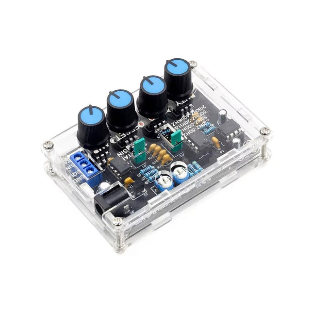
The ICL8038 signal generator delivers versatile waveforms, including sine, triangle, square, and forward/reverse sawtooth, making it suitable for a wide range of applications. Powered by the ICL8038 chip and high-speed operational amplifiers, it ensures exceptional precision and signal stability.
With a frequency range of 5 Hz to 400 kHz, it supports applications from audio to radio frequencies. Its adjustable duty cycle, ranging from 2% to 95%, allows for precise waveform customization to meet various needs.
The DIY kit is beginner-friendly, featuring through-hole components for easy assembly. It includes all necessary parts, an acrylic shell, and a detailed manual, providing everything required to build and use the signal generator efficiently.
Specifications
Frequency range
5 Hz~400 KHz (adjustable)
Power supply voltage
12 V~15 V
Duty cycle range
2~95% (adjustable)
Low distortion sine wave
1%
Low temperature drift
50 ppm/°C
Output triangular wave linearity
0.1%
DC bias range
−7.5 V~7.5 V
Output amplitude range
0.1 V~11 VPP (working voltage 12 V)
Dimensions
89 x 60 x 35 mm
Weight
81 g
Included
PCB incl. all necessary components
Acrylic shell
Manual
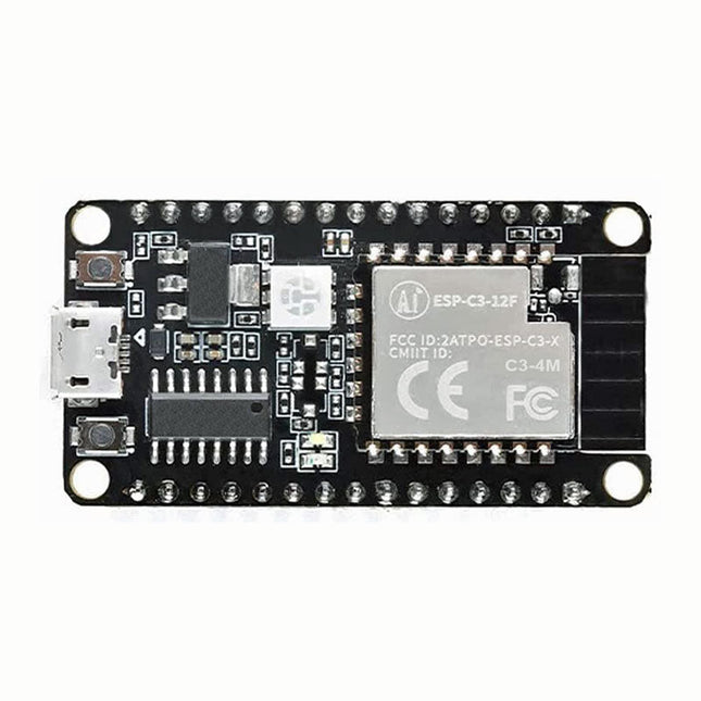
The ESP32-C3 chip has industry-leading low-power performance and radio frequency performance, and supports Wi-Fi IEEE802.11b/g/n protocol and BLE 5.0. The chip is equipped with a RISC-V 32-bit single-core processor with an operating frequency of up to 160 MHz. Support secondary development without using other microcontrollers or processors. The chip has built-in 400 KB SRAM, 384 KB ROM, 8 KB RTC SRAM, built-in 4 MB Flash also supports external Flash. The chip supports a variety of low power consumption working states, which can meet the power consumption requirements of various application scenarios. The chip's unique features such as fine clock gating function, dynamic voltage clock frequency adjustment function, and RF output power adjustable function can achieve the best balance between communication distance, communication rate and power consumption.
The ESP-C3-12F module provides a wealth of peripheral interfaces, including UART, PWM, SPI, I²S, I²C, ADC, temperature sensor and up to 15 GPIOs.
Features
Support Wi-Fi 802.11b/g/n, 1T1R mode data rate up to 150 Mbps
Support BLE5.0, does not support classic Bluetooth, rate support: 125 Kbps, 500 Kbps, 1 Mbps, 2 Mbps
RISC-V 32-bit single-core processor, supports a clock frequency of up to 160 MHz, has 400 KB SRAM, 384 KB ROM, 8 KB RTC SRAM
Support UART/PWM/GPIO/ADC/I²C/I²S interface, support temperature sensor, pulse counter
The development board has RGB three-in-one lamp beads, which is convenient for the second development of customers.
Support multiple sleep modes, deep sleep current is less than 5 uA
Serial port rate up to 5 Mbps
Support STA/AP/STA+AP mode and promiscuous mode
Support Smart Config (APP)/AirKiss (WeChat) of Android and iOS, one-click network configuration
Support serial port local upgrade and remote firmware upgrade (FOTA)
General AT commands can be used quickly
Support secondary development, integrated Windows and Linux development environment
About Flash configuration ESP-C3-12F uses the built-in 4 MB Flash of the chip by default, and supports the external Flash version of the chip.
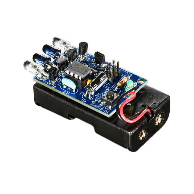
The TV-B-Gone universal remote control allows you to turn virtually any TV On or OFF. You control when you see TV, rather than what you see. The TV-B-Gone Keychain remote is so small that it easily fits in your pocket so that you have it handy whenever you need it, wherever you go: bars, restaurants, laundromats, ballparks, arenas, etc.
The TV-B-Gone Kit is a great way to teach about electronics. When soldered together, it allows you to turn off almost any television within 150 feet or more. It works on over 230 total power codes – 115 American/Asian and another 115 European codes. You can select which zone you want during kit assembly.
This is an unassembled kit which means that soldering and assembly is required – but it’s very easy and a great introduction to soldering in general.
This kit makes the popular TV-B-Gone remote more fun because you created it yourself with some basic soldering and assembly! Show your friends and family how technologically savvy you are, and entertain them with the power of the TV-B-Gone!
The kit is powered by 2x AA batteries and the output comes from 2x narrow beam IR LEDs and 2x wide-beam IR LEDs.
Included
All required parts/components
Required
Tools, soldering iron, and batteries
Downloads
GitHub
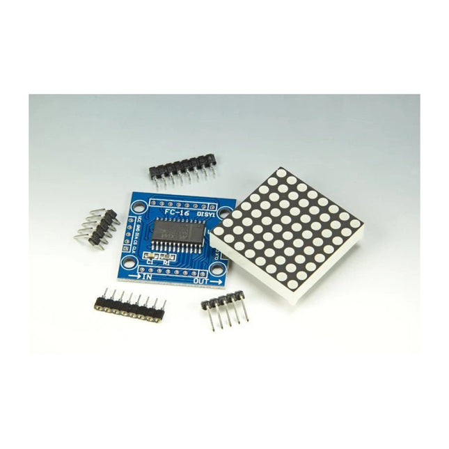
Scrolling text display with eight 8 x 8 LED dot matrix displays (512 LEDs in total). Built around an ESP-12F Wi-Fi module (ESP8266-based) programmed in the Arduino IDE. ESP8266 web server allows control of displayed text, scroll delay and brightness with a mobile phone or other Wi-Fi-connected (portable) device. Features 10 MHz Serial Interface Individual LED Segment Control Decode/No-Decode Digit Selection 150 µA Low-Power Shutdown (Data Retained) Digital and Analog Brightness Control Display Blanked on Power-Up Drive Common-Cathode LED Display Slew-Rate Limited Segment Drivers for Lower EMI (MAX7221) SPI, QSPI, MICROWIRE Serial Interface (MAX7221) 24-Pin DIP and SO Packages
This set contains 3 desoldering tips for digital desoldering stations such as ZD-915 or ZD-8965.
Included
1x Desoldering tip N5-1 (0.8 mm)
1x Desoldering tip N5-2 (1.0 mm)
1x Desoldering tip N5-3 (1.3 mm)
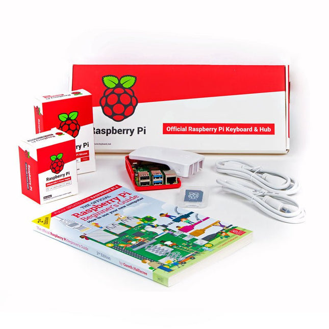
The official Raspberry Pi keyboard and hub is a standard 78-key US keyboard that includes an additional three USB 2.0 type A ports to power other peripherals. The keyboard is available in different language/country options as detailed below. 78-key US keyboard Three USB 2.0 type A ports for powering other peripherals Automatic keyboard language detection USB type A to micro USB type B cable included for connection to compatible computer Ergonomic design for comfortable use Compatible with all Raspberry Pi products
This 'All in One' Raspberry Pi 4 Desktop Starterkit contains all official parts and allows an easy and quick start!
Raspberry Pi 4 Desktop Kit contains:
Raspberry Pi US Keyboard & Mouse
2x micro HDMI to Standard HDMI cable (A/M) 1 m
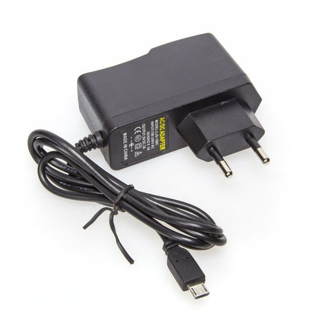
Raspberry Pi 15.3 W USB-C Power Supply (EU version)
Raspberry Pi 4 Case
Official Raspberry Pi Beginner's Guide (English language)
16 GB NOOBS with Raspbian microSD card
Raspberry Pi 4 B is NOT included.
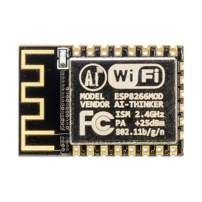
This Wi-Fi module is based on the popular ESP8266 chip. The module is FCC and CE certified and RoHS compliant. Fully compatible with ESP-12E. 13 GPIO pins, 1 analog input, 4 MB flash memory.
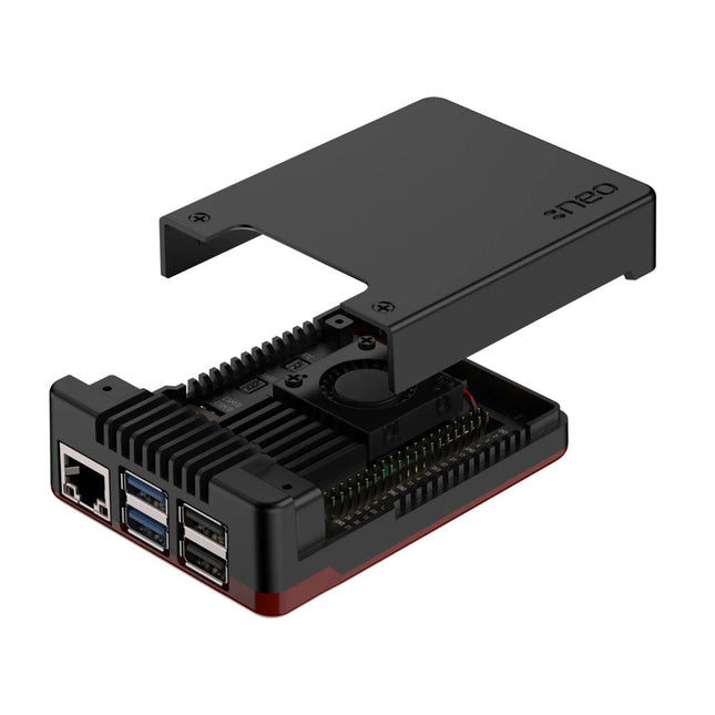
The Argon NEO 5 is redesigned specifically to meet the high demands of the Raspberry Pi 5. It offers an impressive heat dissipation solution for both passive and active cooling.
Aluminum case enclosure with passive cooling fins that act as the heatsink
Air intake vents allow for cool air to enter the case
30 mm PWM fan helps with the airflow and push out hot air to exhaust vents
Simple and beautifully designed
Made with aluminum alloy and polished with a Black & Red finish for stunning aesthetics.
Easy assembly for the 3 part case with the Raspberry Pi 5.
Small foot print allows to bring it anywhere – or easily mount to your desired station with built in mounting points.
Complete access to all ports with the removable top cover.
Superior protection & security
Space grade aluminum helps protect Raspberry Pi 5 board from physical damage.
The case has a screw on top cover to keep the ports safe when not in use.
Optional SD card cover to protect your data even further.
Native Raspberry Pi 5 board support
Integrated power button
LED light display
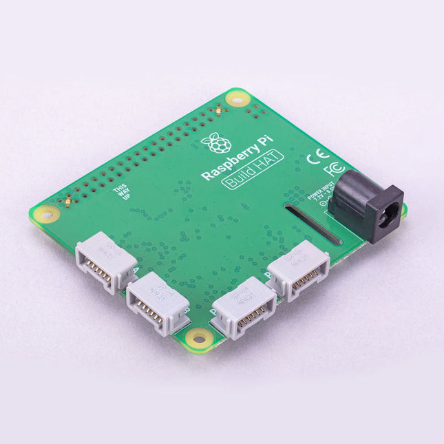
Build robust, intelligent machines that combine Raspberry Pi computing power with LEGO components.
The Raspberry Pi Build HAT provides four connectors for LEGO Technic motors and sensors from the SPIKE Portfolio. The available sensors include a distance sensor, a color sensor, and a versatile force sensor. The angular motors come in a range of sizes and include integrated encoders that can be queried to find their position.
The Build HAT fits all Raspberry Pi computers with a 40-pin GPIO header, including – with the addition of a ribbon cable or other extension device — Raspberry Pi 400. Connected LEGO Technic devices can easily be controlled in Python, alongside standard Raspberry Pi accessories such as a camera module.
Features
Controls up to 4 motors and sensors
Powers the Raspberry Pi (when used with a suitable external PSU)
Easy to use from Python on the Raspberry Pi
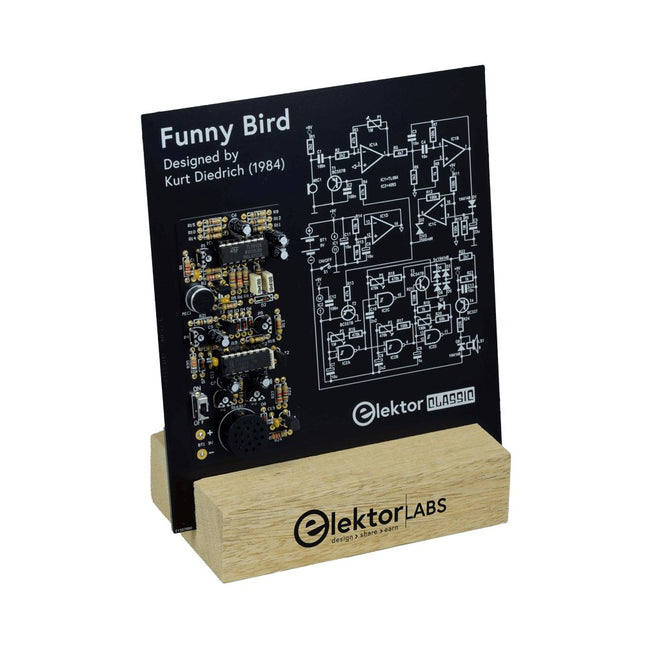
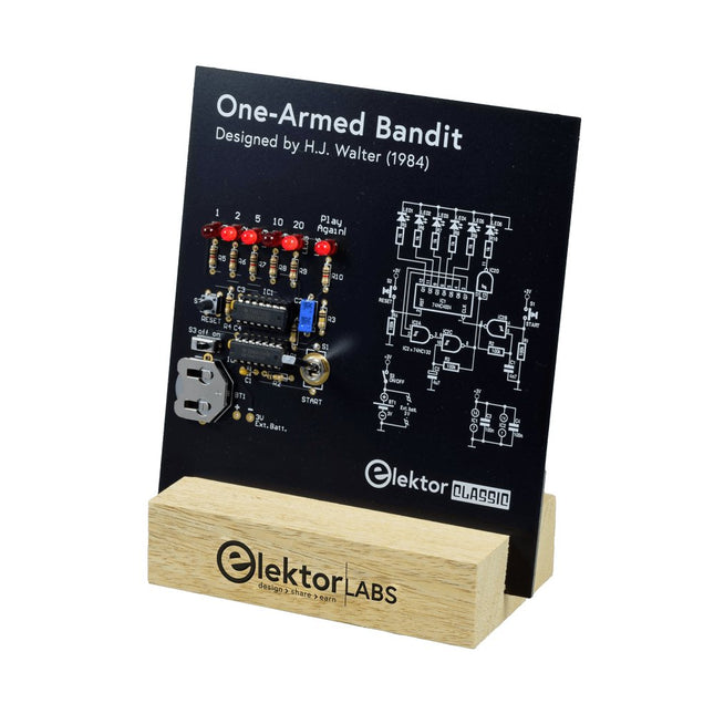
Pull Down Lever For Highest Score!
This Elektor Circuit Classic from 1984 shows a playful application of CMOS 400x series logic ICs in combination with LEDs, a highly popular combination at the time. The project imitates a spinning-digit type slot machine.
The Game
To play the game, first agree on the number of rounds. Player 1 actuates the switch lever as long as desired and releases it. The LEDs then show the score which is the sum of the 50-20-10-5 digits lit up. If the Play Again! LED lights, Player 1 has another, “free” round. If not, it’s Player 2’s turn. The players keep tab of their scores, and the highest score wins.
Features
LEDs Indicate Score
Multi-Player and Play Again!
Elektor Heritage Circuit Symbols
Tried & Tested by Elektor Labs
Educational & Geeky Project
Through-Hole Parts Only
Included
Printed Circuit Board
All Components
Wooden Stand
Bill of Materials
Resistors (5%, 250 mW)
R1,R2,R3,R4 = 100kΩ
R5,R6,R7,R8,R9,R10 = 1kΩ
Capacitors
C1 = 4.7nF, 10%, 50V, 5mm
C2 = 4.7μF, 10%, 63V, axial
C3,C4 = 100nF, 10 %, 50V, ceramic X7R, 5mm
Semiconductors
LED1-LED6 = red, 5mm (T1 3/4)
IC1 = 74HC4024
IC2 = 74HC132
Miscellaneous
S1 = switch, toggle, 21mm lever, SPDT, momentary
S2 = switch, tactile, 24V, 50mA, 6x6mm
S3 = switch, slide, SPDT
IC1,IC2 = IC socket, DIP14
BT1 = PCB-mount CR2032 battery retainer clip
Desktop Stand
PCB 230098-1
Not included: BT1 = CR2032 coin cell battery
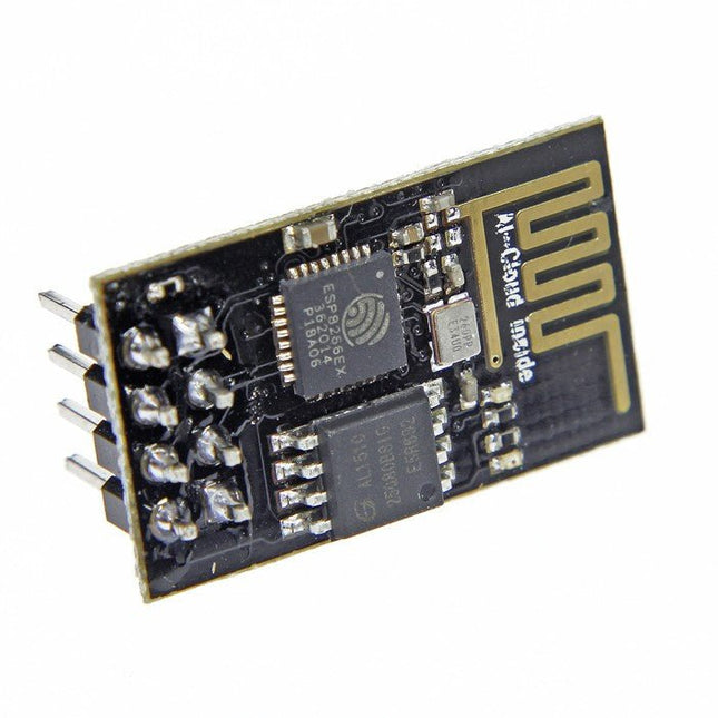
The ESP8266 is an impressive, low cost WiFi module suitable for adding WiFi functionality to an existing microcontroller project via a UART serial connection. The module can even be reprogrammed to act as a standalone WiFi connected device – just add power! 802.11 b/g/n protocol Wi-Fi Direct (P2P), soft-AP Integrated TCP/IP protocol stack This module is a self-contained SOC (System On a Chip) that doesn’t necessarily need a microcontroller to manipulate inputs and outputs as you would normally do with an Arduino , for example, because the ESP-01 acts as a small computer. Thus, you can give a microcontroller internet access like the Wi-Fi shield does to the Arduino, or you can simply program the ESP8266 to not only have access to a Wi-Fi network, but to act as a microcontroller as well, which makes the ESP8266 very versatile.
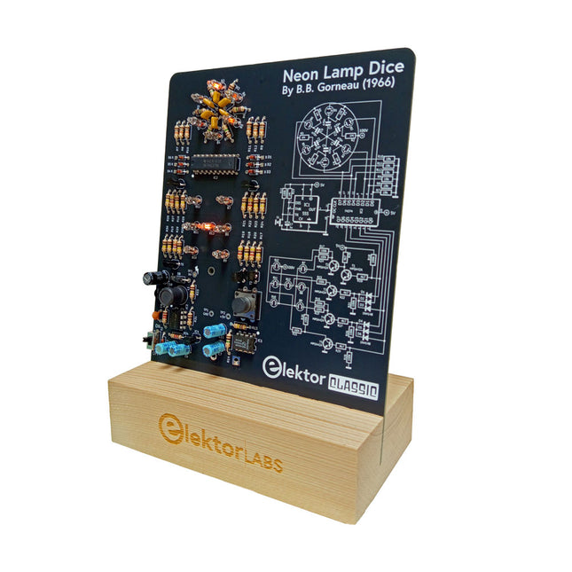
A Retro Roll with a Neon Soul
LED-based dice are common, but their light is cold. Not so for this electronic neon dice, which displays its value with the warm glow of neon lamps. It is perfect for playing games on cold, dark winter evenings. The pips of the dice are neon lamps and the random number generator has six neon lamps to show that it is working.
Even though the dice has an on-board 100-V power supply, it is completely safe. As with all Elektor Classic products, the dice too has its circuit diagram printed on the front while an explanation of how the circuit works can be found on the rear side.
The Neon Lamp Dice comes as a kit of easy-to-solder through-hole parts. The power supply is a 9-V battery (not included).
Features
Warm Vintage Glow
Elektor Heritage Circuit Symbols
Tried & Tested by Elektor Labs
Educational & Geeky Project
Through-Hole Parts Only
Included
Printed Circuit Board
All Components
Wooden Stand
Required
9 V battery
Component List
Resistors (THT, 150 V, 0.25 W)
R1, R2, R3, R4, R5, R6, R14 = 1 MΩ
R7, R8, R9, R10, R11, R12 = 18 kΩ
R13, R15, R16, R17, R18, R21, R23, R24, R25, R26, R28, R30, R33 = 100 kΩ
R32, R34 = 1.2 kΩ
R19, R20, R22, R27, R29 = 4.7 kΩ
R31 = 1 Ω
Capacitors
C1, C2, C3, C4, C5, C6 = 470 nF, 50 V, 5 mm pitch
C7, C9, C11, C12 = 1 µF, 16 V, 2 mm pitch
C8 = 470 pF, 50 V, 5 mm pitch
C10 = 1 µF, 250 V, 2.5 mm pitch
Inductors
L1 = 470 µH
Semiconductors
D1, D2, D3, D4, D5, D6, D7 = 1N4148
D8 = STPS1150
IC1 = NE555
IC2 = 74HC374
IC3 = MC34063
IC4 = 78L05
T1, T2, T3, T4, T5 = MPSA42
T6 = STQ2LN60K3-AP
Miscellaneous
K1 = PP3 9 V battery holder
NE1, NE2, NE3, NE4, NE5, NE6, NE7, NE8, NE9, NE10, NE11, NE12, NE13 = neon light
S2 = Miniature slide switch
S1 = Pushbutton (12 x 12 mm)
The Raspberry Pi Bumper is a snap-on silicone cover that protects the bottom and edges of the Raspberry Pi 5.
Features
One-piece flexible silicone rubber bumper
Enables easy access to the power button
Mounting holes remain accessible underneath the bumper
Downloads
Datasheet