RTL-SDR is an affordable dongle that can be used as a computer based radio scanner for receiving live radio signals in your area. This particular dongle includes a R820T2 tuner, a 1 PPM temperature compensated oscillator (TCXO), SMA F connector. It features an aluminium case with passive cooling via a thermal pad. Moreover, there is a software switchable bias tee circuit, supplementary ESD protection, lower overall noise and built-in direct sampling for HF reception. This device can receive frequencies from 500 kHz to 1.7 GHz and has up to 3.2 MHz of instantaneous bandwidth (2.4 MHz stable).
Note: RTL-SDR dongles are RX only.
You can use this kit either for terrestrial or satellite reception just by changing the orientation of the antenna. Thanks to the included mounts and extension cables it is possible to temporarily place the antenna outside for a better reception. Other potential applications are general radio scanning, air traffic control, public safety radio, ADSB, ACARS, trunked radio, P25 digital voice, POCSAG, weather balloons, APRS, NOAA APT weather satellites, radio astronomy, meteor scatter monitoring etc.
Included
RTL-SDR V3 Dongle (R820T2 RTL2832U 1PPM TCXO SMA)
2x 23 cm to 1 m telescopic antenna
2x 5 cm to 13 cm telescopic antenna
Dipole Antenna Base with 60 cm RG174 extension cable
3 m RG174 extension cable
Flexible Tripod Mount
Suction Cup Mount
Downloads
Datasheet
Quick Start Guide
SDR# User Guide
Dipole Antenna Kit Guide
The ZD-915 is a digital desoldering station with ESD protection and digital display of both the actual and set value on an LCD screen. This desoldering station has high power in a compact and robust housing and makes desoldering easy, because it can be operated with one hand.
The ZD-915 features a soldering gun that houses a filter that catches any sucked material, so you only need to replace the filters to continue. There is also a temperature sensor in the tip so that temperature fluctuations can be quickly absorbed.
Features
The temperature is easily adjusted by simple up/down buttons.
140 W temperature controlled soldering station with adjustable range from 160°C to 480°C.
The desoldering station is designed for lead free desoldering specially.
The side of the station features a typical holder with sponge.
An illuminated power on/off is also loacted on the front.
Specifications
Station
Voltage supply
220-240 V
Power consumption
140 W
Vakuum pressure
600 mm HG
Desoldering Gun
Power consumption
24 V AC 80 WHeat up rating 130 W
Temperature
160-480 °C
Heating element
Ceramic heater
Included
1x ZD-915 Desoldering station
2x Spare soldering tip
3x Cleaning needle for desoldering tips
1x Spare filter for desoldering gun
1x Manual
This upgraded version 2.0 (available exclusively from Elektor) contains the following improvements:
Enhanced protective earthing (PE) for furnace chassis
Extra thermal insulation layer around furnace to reduce odors
Connection to a computer, allowing curve editing on a PC
Features such as constant temperature control and timing functions
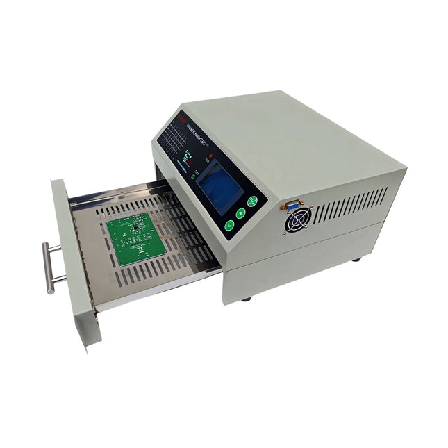
The infrared IC heater T-962 v2.0 is a microprocessor-controlled reflow oven that you can use for effectively soldering various SMD and BGA components. The whole soldering process can be completed automatically and it is very easy to use. This machine uses a powerful infrared emission and circulation of the hot air flow, so the temperature is being kept very accurate and evenly distributed.
A windowed drawer is designed to hold the work-piece, and allows safe soldering techniques and the manipulation of SMDBGA and other small electronic parts mounted on a PCB assembly. The T-962 v2.0 may be used to automatically rework solder to correct bad solder joints, remove/replace bad components and complete small engineering models or prototypes.
Features
Large infrared soldering area
Effective soldering area: 180 x 235 mm; this increases the usage range of this machine drastically and makes it an economical investment.
Choice of different soldering cycles
Parameters of eight soldering cycles are pre defined and the entire soldering process can completed automatically from Preheat, Soak and Reflow through to cool down.
Special heat up and temperature equalization with all designs
Uses up to 800 Watts of energy efficient Infrared heating and air circulation to re-flow solder.
Ergonomic design, practical and easily operated
Good build quality but at the same time light weight and a small footprint allows the T-962 v2.0 to be easily bench positioned transported or stored.
Large number of available functions
The T-962 v2.0 can solder most small parts of PCB boards, for example CHIP, SOP, PLCC, QFP, BGA etc. It is the ideal rework solution from single runs to on-demand small batch production.
Specifications
Soldering area (max)
180 x 235 mm (7.1 x 9.3")
Power (max)
800 W
Temperature range
0-280°C (32-536°F)
Heating method
Infrared
Processing time
1~8 minutes
Power supply
220 V AC/50 Hz
Display
LCD with Backlight
Control mode
8 intelligent temperature curves
Dimensions
310 x 290 x 170 mm (12.2 x 11.4 x 6.7")
Weight
6.2 kg
Included
1x T-962 v2.0 Reflow Soldering Oven (Elektor Version)
2x Fuses
1x Power cord (EU)
Downloads
Manual
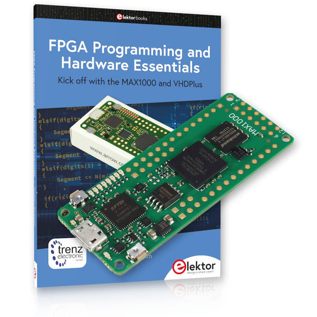
Kick off to FPGA Programming with the MAX1000 Board and VHDPlus
Ready to master FPGA programming? With this bundle, you'll dive into the world of Field-Programmable Gate Arrays (FPGAs) – a configurable integrated circuit that can be programmed after manufacturing. Bring your ideas to life, from simple projects to complete microcontroller systems!
The MAX1000 is a compact and powerful FPGA development board packed with features like memory, user LEDs, push-buttons, and flexible I/O ports. It’s the ideal starting point for anyone wanting to learn about FPGAs and Hardware Description Languages (HDLs).
With the enclosed book "FPGA Programming and Hardware Essentials" you'll get hands-on with the VHDPlus programming language – a simpler version of VHDL. You'll work on practical projects using the MAX1000, helping you gain the skills and confidence to unleash your creativity.
Projects in the Book
Arduino-driven BCD to 7-Segment Display Decoder
Use an Arduino Uno R4 to supply BCD data to the decoder, counting from 0 to 9 with a one-second delay
Multiplexed 4-Digit Event Counter
Create an event counter that displays the total count on a 4-digit display, incrementing with each button press
PWM Waveform with Fixed Duty Cycle
Generate a PWM waveform at 1 kHz with a fixed duty cycle of 50%
Ultrasonic Distance Measurement
Measure distances using an ultrasonic sensor, displaying the results on a 4-digit 7-segment LED
Electronic Lock
Build a simple electronic lock using combinational logic gates with push buttons and an LED output
Temperature Sensor
Monitor ambient temperature with a TMP36 sensor and display the readings on a 7-segment LED
MAX1000 FPGA Development Board
The MAX1000 is a customizable IoT/Maker Board ready for evaluation, development and/or use in a product. It is built around the Intel MAX10 FPGA, which is the industry’s first single chip, non-volatile programmable logic device (PLDs) to integrate the optimal set of system components.
Users can now leverage the power of tremendous re-configurability paired with a high-performance, low-power FPGA system. Providing internally stored dual images with self-configuration, comprehensive design protection features, integrated ADCs and hardware to implement the Nios II 32-bit microcontroller IP, MAX10 devices are ideal solution for system management, protocol bridging, communication control planes, industrial, automotive and consumer applications.
The MAX1000 is equipped with an Arrow USB Programmer2, SDRAM, flash memory, accelerometer sensor and PMOD/Arduino MKR connectors making it a fully featured plug and play solution without any additional costs.
Specifications
MAX 10
8 kLE
- Flash
Dual inside
- ADC
8x 12 Bit
- Temperature Range
0~85°C
- Supply
USB/pins
SDRAM
8 MB
3-axis MEMS
LIS3DH
USB Programmer
on board
MEMS Oscillator
12 MHz
Switch/LED
2x / 8x
Contents of the Bundle
Book: FPGA Programming and Hardware Essentials (normal price: €40)
MAX1000 FPGA Development Board (normal price: €45)
Downloads
Software
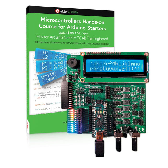
Realize your own projects with the Elektor Arduino Nano MCCAB Training Board
The microcontroller is probably the most fascinating subfield of electronics. Due to the multitude of functions, it combines on its chip, it is a universal multi-tool for developers to realize their projects. Practically every device of daily use today is controlled by a microcontroller. However, for an electronic layman, realizing his own ideas with a microcontroller has so far remained a pipe dream due to its complexity. The Arduino concept has largely simplified the use of microcontrollers, so that now even laymen can realize their own electronics ideas with a microcontroller.
Book & Hardware in the Bundle: 'Learning by Doing'
This book, which is included in the bundle, shows how you can realize your own projects with a microcontroller even without much experience in electronics and programming languages. It is a microcontrollers hands-on course for starters, because after an overview of the internals of the microcontroller and an introduction to the programming language C, the focus of the course is on the practical exercises. The reader acquires the necessary knowledge by 'learning by doing': in the extensive practical section with 12 projects and 46 exercises, what is learned in the front part of the book is underpinned with many examples. The exercises are structured in such a way that the user is given a task to solve using the knowledge built up in the theoretical part of the book. Each exercise is followed by a sample solution that is explained and commented on in detail, which helps the user to solve problems and compare it with his own solution.
Arduino IDE
The Arduino IDE is a software development environment that can be downloaded for free to your own PC and that contains the entire software package needed for your own microcontroller projects. You write your programs ('apps') with the IDE’s editor in the C programming language. You translate them into the bits and bytes that the microcontroller understands using the Arduino IDE's built-in compiler, and then load them into the microcontroller's memory on the Elektor Arduino MCCAB Nano Training Board via a USB cable.
Query or control external sensors, motors or assemblies
In addition to an Arduino Nano microcontroller module, the Elektor Arduino Nano MCCAB Training Board contains all the components required for the exercises, such as light-emitting diodes, switches, pushbuttons, acoustic signal transmitters, etc. External sensors, motors or assemblies can also be queried or controlled with this microcontroller training system.
Specifications (Arduino Nano MCCAB Training Board)
Power Supply
Via the USB connection of the connected PC or an external power supply unit (not included)
Operating Voltage
+5 Vcc
Input Voltage
All inputs
0 V to +5 V
VX1 and VX2
+8 V to +12 V (only when using an external power supply)
Hardware periphery
LCD
2x16 characters
Potentiometer P1 & P2
JP3: selection of operating voltage of P1 & P2
Distributor
SV4: Distributor for the operating voltagesSV5, SV6: Distributor for the inputs/outputs of the microcontroller
Switches and buttons
RESET button on the Arduino Nano module 6x pushbutton switches K1 ... K6 6x slide switches S1 ... S6 JP2: Connection of the switches with the inputs of the microcontroller
Buzzer
Piezo buzzer Buzzer1 with jumper on JP6
Indicator lights
11 x LED: Status indicator for the inputs/outputs LED L on the Arduino Nano module, connected to GPIO D13 JP6: Connection of LEDs LD10 ... LD20 with GPIOs D2 ... D12
Serial interfacesSPI & I²C
JP4: Selection of the signal at pin X of the SPI connector SV12 SV9 to SV12: SPI interface (3.3 V/5 V) or I²C interface
Switching output for external devices
SV1, SV7: Switching output (maximum +24 V/160 mA, externally supplied) SV2: 2x13 pins for connection of external modules
3x3 LED matrix(9 red LEDs)
SV3: Columns of the 3x3 LED matrix (outputs D6 ... D8) JP1: Connection of the rows with the GPIOs D3 ... D5
Software
Library MCCABLib
Control of hardware components (switches, buttons, LEDs, 3x3 LED matrix, buzzer) on the MCCAB Training Board
Operating Temperature
Up to +40 °C
Dimensions
100 x 100 x 20 mm
Specifications (Arduino Nano)
Microcontroller
ATmega328P
Architecture
AVR
Operating Voltage
5 V
Flash Memory
32 KB, of which 2 KB used by bootloader
SRAM
2 KB
Clock Speed
16 MHz
Analog IN Pins
8
EEPROM
1 KB
DC Current per I/O Pins
40 mA on one I/O pin, total maximum 200 mA on all pins together
Input Voltage
7-12 V
Digital I/O Pins
22 (6 of which are PWM)
PWM Output
6
Power Consumption
19 mA
Dimensions
18 x 45 mm
Weight
7 g
Included
Elektor Arduino Nano MCCAB Training Board
Arduino Nano
Book: Microcontrollers Hands-on Course for Arduino Starters
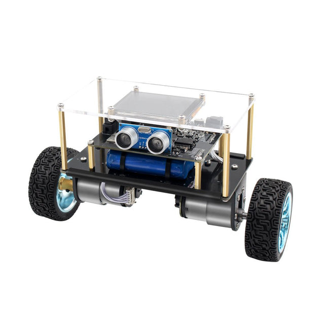
Arduino-compatible, ESP32-controlled, 2-wheeled Balancing Robot
The Elektor Mini-Wheelie is an experimental autonomous self-balancing robot platform. Based on an ESP32-S3 microcontroller, the self-balancing robot is fully programmable using the Arduino environment and open-source libraries. Its wireless capabilities allow it to be controlled remotely over Wi-Fi, Bluetooth or ESP-NOW or to communicate with a user or even another robot.
An ultrasonic transducer is available for detecting obstacles. Its color display can be used for displaying cute facial expressions or, for the more down-to-earth users, cryptic debug messages.
The robot comes as a neat kit of parts that you must assemble yourself. Everything is included, even a screwdriver.
Note: The Mini-Wheelie is an educational development platform intended for learning, experimentation, and robotics development. It is not classified as a toy for children, and its features, documentation, and intended audience reflect this purpose. The product is aimed at students, educators, and developers who wish to explore robotics, programming, and hardware integration in an educational setting.
Specifications
ESP32-S3 microcontroller with Wi-Fi and Bluetooth
MPU6050 6-axis Inertial Measurement Unit (IMU)
Two independently controlled 12 V electric motors with tachometer
Ultrasonic transducer
2.9" TFT color display (320 x 240)
MicroSD card slot
Battery power monitor
3S rechargeable Li-Po battery (11.1 V/2200 mAh)
Battery charger included
Arduino-based open-source software
Dimensions (W x L x H): 23 x 8 x 13 cm
Included
1x ESP32-S3 Mainboard + MPU6050 module
1x LCD board (2.9 inch)
1x Ultrasonic sensor
1x Battery pack (2200 mAh)
1x Battery charger
1x Motor tyre kit
1x Case board
1x Acrylic board
1x Screwdriver
1x Protective strip
1x Flex cable B (8 cm)
1x Flex cable A (12 cm)
1x Flex cable C
4x Copper column A (25 mm)
4x Copper column B (55 mm)
4x Copper column C (5 mm)
2x Plastic nylon column
8x Screws A (10 mm)
24x Screws B (M3x5)
8x Nuts
24x Metal washers
2x Zip tie
1x MicroSD card (32 GB)
Downloads
Documentation
Raspberry Pi-based Eye Catcher
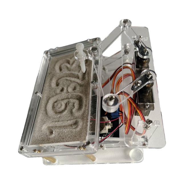
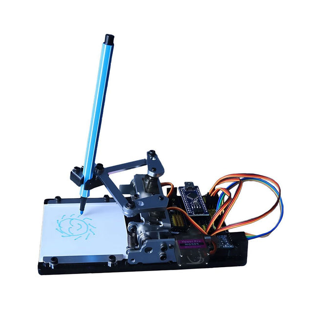
A standard sand clock just shows how time passes. In contrast, this Raspberry Pi Pico-controlled sand clock shows the exact time by “engraving” the four digits for hour and minute into the layer of sand. After an adjustable time the sand is flattened out by two vibration motors and everything begins all over again.
At the heart of the sand clock are two servo motors driving a writing pen through a pantograph mechanism. A third servo motor lifts the pen up and down. The sand container is equipped with two vibration motors to flatten the sand. The electronic part of the sand clock consists of a Raspberry Pi Pico and an RTC/driver board with a real-time clock, plus driver circuits for the servo motors.
A detailed construction manual is available for downloading.
Features
Dimensions: 135 x 110 x 80 mm
Build time: approx. 1.5 to 2 hours
Included
3x Precut acrylic sheets with all mechanical parts
3x Mini servo motors
2x Vibration motors
1x Raspberry Pi Pico
1x RTC/driver board with assembled parts
Nuts, bolts, spacers, and wires for the assembly
Fine-grained white sand
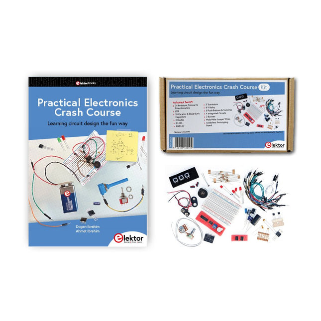
Getting started in electronics is not as difficult as you may think. With this bundle (book + kit of parts), you can explore and learn the most important electrical and electronics engineering concepts in a fun way by doing various experiments. You will learn electronics practically without getting into complex technical jargon and long calculations. As a result, you will be creating your own projects soon.
This kit contains the components required to build most of the detailed examples of the book on a breadboard and try them out for real.
The kit can, of course, also be used without the book for building other circuits and doing your own experiments.
Kit contents
1x 39 Ω, 1 W resistor
1x 47 Ω resistor
1x 180 Ω resistor
1x 330 Ω resistor
3x 1 kΩ resistor
1x 2.2 kΩ resistor
1x 3.9 kΩ resistor
1x 6.8 kΩ resistor
1x 10 kΩ resistor
1x 15 kΩ resistor
1x 22 kΩ resistor
1x 33 kΩ resistor
1x 47 kΩ resistor
1x 56 kΩ resistor
1x 82 kΩ resistor
1x 120 kΩ resistor
1x 680 kΩ resistor
2x 100 kΩ resistor
1x 10 kΩ trimmer
1x 10 kΩ linear potentiometer
1x 100 kΩ linear potentiometer
1x LDR
1x 1 nF ceramic capacitor
2x 10 nF ceramic capacitor
1x 100 nF ceramic capacitor
1x 1 µF, 25 V aluminium electrolytic capacitor
2x 10 µF, 25 V aluminium electrolytic capacitor
1x 100 µF, 25 V aluminium electrolytic capacitor
1x 470 µF, 25 V aluminium electrolytic capacitor
1x 1000 µF, 25 V aluminium electrolytic capacitor
1x RGB LED, Common-Cathode (CC)
1x 1N4148 small signal diode
1x 1N4733A 5.1 V, 1 W Zener diode
3x LED, red
2x BC337 NPN transistor
1x IRFZ44N N-channel MOSFET
2x NE555 timer
1x LM393 comparator
1x 74HCT08 quad AND gate
3x Tactile switch
2x SPDT switch
1x Relay, SPDT, 9 VDC
1x Active buzzer
1x Passive buzzer
50 cm Solid wire, 16 AWG, unjacketed
2x PP3 9 V battery clip
1x Breadboard
20x Jumper wire
This bundle contains:
Practical Electronics Crash Course Kit (valued at: €45)
Book: Practical Electronics Crash Course (normal price: €45)
The QA403 is QuantAsylum's fourth-generation audio analyzer. The QA403 extends the functionality of the QA402 with improved noise and distortion performance, in addition to a flatter response at band edges. The compact size of the QA403 means you can take it just about anywhere.
Features
24-bit ADC/DAC
Up to 192 kS/s
Fully isolated from PC
Differential Input/Output
USB powered
Built-in Attenuator
Fast Bootup and Driverless
The QA403 is a driverless USB device, meaning it’s ready as soon as you plug it in. The software is free and it is quick and easy to move the hardware from one machine to the next. So, if you need to head to the factory to troubleshoot a problem or take the QA403 home for a work-from-home day, you can do it without hassle.
No-Cal Design
The QA403 comes with a factory calibration in its flash memory, ensuring consistent unit-to-unit performance. On your manufacturing line you can install another QA403 and be confident what you read on one unit will be very similar to the next unit. It is not expected that re-calibration will be required at regular intervals.
Measurements
Making basic measurements is quick and easy. In a few clicks you will understand the frequency response, THD(+N), gain, SNR and more of your device-under test.
Dynamic Range
The QA403 offers 8 gain ranges on the input (0 to +42 dBV in 6 steps), and 4 gain ranges on the output (-12 to +18 dBV in 10 dB steps). This ensures consistent performance over very wide ranges of input and output levels. The maximum AC input to the QA403 is +32 dBV = 40 Vrms. The maximum DC is ±40 V, and the maximum ACPEAK + DC = ±56 V.
Easy Programmability
The QA403 supports a REST interface, making it easy to automate measurements in just about any language you might anticipate. From Python to C++ to Visual Basic—if you know how to load a web page in your favorite language, you can control the QA403 remotely. Measurements are fast and responsive, usually with dozens of commands being processed per second.
Isolated and USB Powered
The QA403 is isolated from the PC, meaning you are measuring your DUT and not chasing some phantom ground loop. The QA403 is USB powered, like nearly all our instruments. If you are setting up remotely, throw a powered hub in your bag and your entire test setup can be running with a minimum of cables.
Goodbye Soundcard, Hello QA403
Tired of trying to make a soundcard work? The calibration nightmare? The lack of gain stages? The limited drive? Are you tired of dealing with the fixed input ranges? The worry that you might destroy it with too much DC or AC? Tired of the ground loops? That’s why QuantAsylum built the QA403.
Specifications
Dimensions
177 x 44 x 97 mm (W x H x D)
Weight
435 g
Case Material
Powder-coating Aluminum (2 mm thick front panel, 1.6 mm thick top/bottom)
Downloads
Datasheet
Manual
GitHub
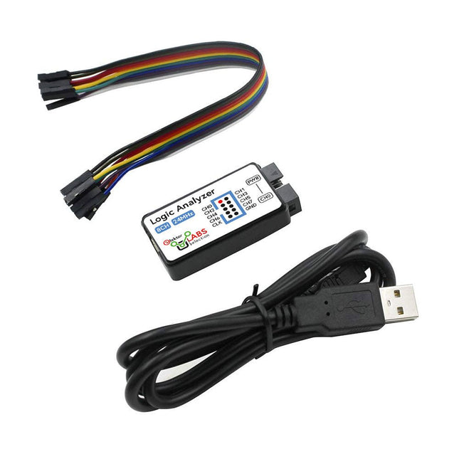
This USB Logic Analyzer is an 8-channel logic analyzer with each input dual purposed for analog data recording. It is perfect for debugging and analyzing signals like I²C, UART, SPI, CAN and 1-Wire. It operates by sampling a digital input connected to a device under test (DUT) at a high sample rate. The connection to the PC is via USB.
Specifications
Channels
8 digital channels
Maximum sampling rate
24 MHz
Maximum input voltage
0~5 V
Operating temperature
0~70°C
Input impedance
1 MΩ || 10 pF
Supported protocols
I²C, SPI, UART, CAN, 1-Wire, etc.
PC connection
USB
Dimensions
55 x 28 x 14 mm
Included
USB Logic Analyzer (8-ch, 24 MHz)
USB Cable
Jumper Wire Ribbon Cable
Downloads
Software
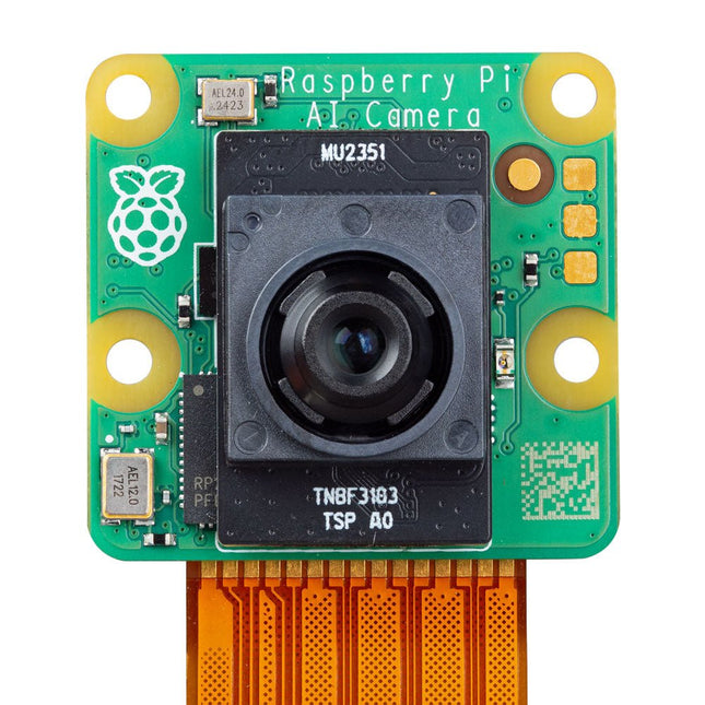
The Raspberry Pi AI Camera is a compact camera module based on the Sony IMX500 Intelligent Vision Sensor. The IMX500 combines a 12 MP CMOS image sensor with on-board inferencing acceleration for various common neural network models, allowing users to develop sophisticated vision-based AI applications without requiring a separate accelerator.
The AI Camera enhances captured still images or video with tensor metadata, while keeping the Raspberry Pi's processor free for other tasks. Support for tensor metadata in the libcamera and Picamera2 libraries, as well as the rpicam-apps application suite, ensures ease of use for beginners while providing unparalleled power and flexibility for advanced users.
The Raspberry Pi AI Camera is compatible with all Raspberry Pi models.
Features
12 MP Sony IMX500 Intelligent Vision Sensor
Sensor modes: 4056x3040 (@ 10fps), 2028x1520 (@ 30fps)
1.55 x 1.55 µm cell size
78-degree field of view with manually adjustable focus
Integrated RP2040 for neural network and firmware management
Specifications
Sensor
Sony IMX500
Resolution
12.3 MP (4056 x 3040 pixels)
Sensor size
7.857 mm (type 1/2.3)
Pixel size
1.55 x 1.55 μm
IR cut filter
Integrated
Autofocus
Manual adjustable focus
Focus range
20 cm – ∞
Focal length
4.74 mm
Horizontal FOV
66 ±3°
Vertical FOV
52.3 ±3°
Focal ratio (F-stop)
F1.79
Output
Image (Bayer RAW10), ISP output (YUV/RGB), ROI, metadata
Input tensor maximum size
640 x 640 (H x V)
Framerate
• 2x2 binned: 2028x1520 10-bit 30fps• Full resolution: 4056x3040 10-bit 10fps
Ribbon cable length
20 cm
Cable connector
15 x 1 mm FPC or 22 x 0.5 mm FPC
Dimensions
25 x 24 x 11.9 mm
Downloads
Datasheet
Documentation
This versatile plotter robot arm DIY kit for Arduino is equipped with MG90S metal gear servo motors to ensure precise and stable drawing movements.
Features
Fully compatible with Arduino IDE, includes complete source code for easy development and customization.
Equipped with robust MG90S metal gear servo motors for accuracy and durability.
Includes a Bluetooth module enabling wireless operation via a dedicated app.
Specially designed robotic arm tip securely holds pens or markers with a diameter of 8-10 mm, ideal for sketches and detailed drawings.
Included
Arduino-compatible Nano motherboard
Nano expansion board
Bluetooth module
MG90S all-metal gear servo motors
Aluminum structural frame
Thickened stable base plate
Screw and fastening accessories
Connecting wires
USB data cable
The Red Pitaya (STEMlab) is a credit card-sized, open-source test and measurement board that can be used to replace most measurement instruments used in electronics laboratories. With a single click, the board can transform into a web-based oscilloscope, spectrum analyser, signal generator, LCR meter, Bode plotter, and microcontroller.
The Red Pitaya (STEMlab) can replace the many pieces of expensive measurement equipment found at professional research organisations and teaching laboratories. The device, that based on Linux, includes an FPGA, digital signal processing (DSP), dual core ARM Cortex processor, signal acquisition and generation circuitry, micro USB socket, microSD card slot, RJ45 socket for Ethernet connection, and USB socket – all powered from an external mains adaptor.
This book is an introduction to electronics. It aims to teach the principles and applications of basic electronics by carrying out real experiments using the Red Pitaya (STEMlab). The book includes many chapters on basic electronics and teaches the theory and use of electronic components including resistors, capacitors, inductors, diodes, transistors, and operational amplifiers in electronic circuits. Many fun and interesting Red Pitaya (STEMlab) experiments are included in the book. The book also makes an introduction to visual programming environment.
The book is written for college level and first year university students studying electrical or electronic engineering.
The Raspberry Pi AI HAT+ is an expansion board designed for the Raspberry Pi 5, featuring an integrated Hailo AI accelerator. This add-on offers a cost-effective, efficient, and accessible approach to incorporating high-performance AI capabilities, with applications spanning process control, security, home automation, and robotics.
Available in models offering 13 or 26 tera-operations per second (TOPS), the AI HAT+ is based on the Hailo-8L and Hailo-8 neural network accelerators. The 13 TOPS model efficiently supports neural networks for tasks like object detection, semantic and instance segmentation, pose estimation, and more. This 26 TOPS variant accommodates larger networks, enables faster processing, and is optimized for running multiple networks simultaneously.
The AI HAT+ connects via the Raspberry Pi 5’s PCIe Gen3 interface. When the Raspberry Pi 5 is running a current version of the Raspberry Pi OS, it automatically detects the onboard Hailo accelerator, making the neural processing unit (NPU) available for AI tasks. Additionally, the rpicam-apps camera applications included in Raspberry Pi OS seamlessly support the AI module, automatically using the NPU for compatible post-processing functions.
Included
Raspberry Pi AI HAT+ (26 TOPS)
Mounting hardware kit (spacers, screws)
16 mm GPIO stacking header
Downloads
Datasheet
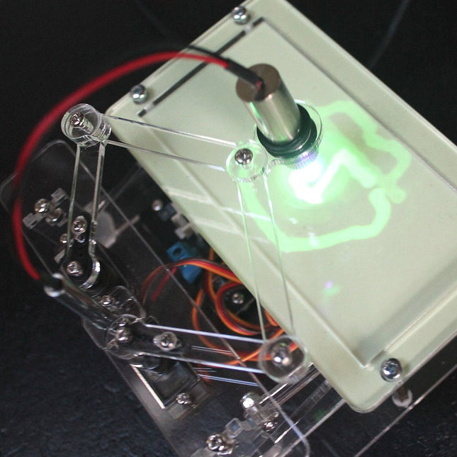
This bundle contains the popular Elektor Sand Clock for Raspberry Pi Pico and the new Elektor Laser Head Upgrade, offering even more options for displaying the time. Not only can you "engrave" the current time in sand, you can now alternatively write it on a glow-in-the-dark foil or create green drawings.
Contents of the bundle
Elektor Sand Clock for Raspberry Pi Pico (normal price: €50)
Elektor Laser Head Upgrade for Sand Clock (normal price: €35)
Elektor Sand Clock for Raspberry Pi (Raspberry Pi-based Eye Catcher)
A standard sand clock just shows how time passes. In contrast, this Raspberry Pi Pico-controlled sand clock shows the exact time by "engraving" the four digits for hour and minute into the layer of sand. After an adjustable time the sand is flattened out by two vibration motors and everything begins all over again.
At the heart of the sand clock are two servo motors driving a writing pen through a pantograph mechanism. A third servo motor lifts the pen up and down. The sand container is equipped with two vibration motors to flatten the sand. The electronic part of the sand clock consists of a Raspberry Pi Pico and an RTC/driver board with a real-time clock, plus driver circuits for the servo motors.
A detailed construction manual is available for downloading.
Features
Dimensions: 135 x 110 x 80 mm
Build time: approx. 1.5 to 2 hours
Included
3x Precut acrylic sheets with all mechanical parts
3x Mini servo motors
2x Vibration motors
1x Raspberry Pi Pico
1x RTC/driver board with assembled parts
Nuts, bolts, spacers, and wires for the assembly
Fine-grained white sand
Elektor Laser Head Upgrade for Sand Clock
The new Elektor Laser Head transforms the Sand Clock into a clock that writes the time on glow-in-the-dark film instead of sand. In addition to displaying the time, it can also be used to create ephemeral drawings. The 5 mW laser pointer, with a wavelength of 405 nm, produces bright green drawings on the glow-in-the-dark film. For best results, use the kit in a dimly lit room. Warning: Never look directly into the laser beam!
The kit includes all the necessary components, but soldering three wires is required.
Note: This kit is also compatible with the original Arduino-based Sand Clock from 2017. For more details, see Elektor Magazine 1-2/2017 and Elektor Magazine 1-2/2018.
The Elektor Laser Head transforms the Elektor Sand Clock into a clock that writes the time on glow-in-the-dark film instead of sand. In addition to displaying the time, it can also be used to create ephemeral drawings. The 5 mW laser pointer, with a wavelength of 405 nm, produces bright green drawings on the glow-in-the-dark film. For best results, use the kit in a dimly lit room. Warning: Never look directly into the laser beam!
The kit includes all the necessary components, but soldering three wires is required.
Note: This kit is also compatible with the original Arduino-based Sand Clock from 2017. For more details, see Elektor Magazine 1-2/2017 and Elektor Magazine 1-2/2018.
The Elektor Arduino Nano MCCAB Training Board contains all the components (incl. Arduino Nano) required for the exercises in the "Microcontrollers Hands-on Course for Arduino Starters", such as light-emitting diodes, switches, pushbuttons, acoustic signal transmitters, etc. External sensors, motors or assemblies can also be queried or controlled with this microcontroller training system.
Specifications (Arduino Nano MCCAB Training Board)
Power Supply
Via the USB connection of the connected PC or an external power supply unit (not included)
Operating Voltage
+5 Vcc
Input Voltage
All inputs
0 V to +5 V
VX1 and VX2
+8 V to +12 V (only when using an external power supply)
Hardware periphery
LCD
2x16 characters
Potentiometer P1 & P2
JP3: selection of operating voltage of P1 & P2
Distributor
SV4: Distributor for the operating voltagesSV5, SV6: Distributor for the inputs/outputs of the microcontroller
Switches and buttons
RESET button on the Arduino Nano module 6x pushbutton switches K1 ... K6 6x slide switches S1 ... S6 JP2: Connection of the switches with the inputs of the microcontroller
Buzzer
Piezo buzzer Buzzer1 with jumper on JP6
Indicator lights
11 x LED: Status indicator for the inputs/outputs LED L on the Arduino Nano module, connected to GPIO D13 JP6: Connection of LEDs LD10 ... LD20 with GPIOs D2 ... D12
Serial interfacesSPI & I²C
JP4: Selection of the signal at pin X of the SPI connector SV12 SV9 to SV12: SPI interface (3.3 V/5 V) or I²C interface
Switching output for external devices
SV1, SV7: Switching output (maximum +24 V/160 mA, externally supplied) SV2: 2x13 pins for connection of external modules
3x3 LED matrix(9 red LEDs)
SV3: Columns of the 3x3 LED matrix (outputs D6 ... D8) JP1: Connection of the rows with the GPIOs D3 ... D5
Software
Library MCCABLib
Control of hardware components (switches, buttons, LEDs, 3x3 LED matrix, buzzer) on the MCCAB Training Board
Operating Temperature
Up to +40 °C
Dimensions
100 x 100 x 20 mm
Specifications (Arduino Nano)
Microcontroller
ATmega328P
Architecture
AVR
Operating Voltage
5 V
Flash Memory
32 KB, of which 2 KB used by bootloader
SRAM
2 KB
Clock Speed
16 MHz
Analog IN Pins
8
EEPROM
1 KB
DC Current per I/O Pins
40 mA on one I/O pin, total maximum 200 mA on all pins together
Input Voltage
7-12 V
Digital I/O Pins
22 (6 of which are PWM)
PWM Output
6
Power Consumption
19 mA
Dimensions
18 x 45 mm
Weight
7 g
Included
1x Elektor Arduino Nano Training Board MCCAB
1x Arduino Nano
If you enjoy DIY electronics, projects, software and robots, you’ll find this book intellectually stimulating and immediately useful. With the right parts and a little guidance, you can build robot systems that suit your needs more than overpriced commercial systems can.
20 years ago, robots based on simple 8-bit processors and touch sensors were the norm. Now, it’s possible to build multi-core robots that can react to their surroundings with intelligence. Today’s robots combine sensor readings from accelerometers, gyroscopes and computer vision sensors to learn about their environments. They can respond using sophisticated control algorithms and they can process data both locally and in the cloud.
This book, which covers the theory and best practices associated with advanced robot technologies, was written to help roboticists, whether amateur hobbyist or professional, take their designs to the next level. As will be seen, building advanced applications does not require extremely costly robot technology. All that is needed is simply the knowledge of which technologies are out there and how best to use each of them.
Each chapter in this book will introduce one of these different technologies and discuss how best to use it in a robotics application. On the hardware side, we’ll cover microcontrollers, servos, and sensors, hopefully inspiring you to design your own awe-inspiring, next-generation systems. On the software side, we’ll cover programming languages, debugging, algorithms, and state machines. We’ll focus on the Arduino, the Parallax Propeller, Revolution Education PICAXE and projects I’ve with which I’ve been involved, including the TBot educational robot, the PropScope oscilloscope, the 12Blocks visual programming language, and the ViewPort development environment. In addition, we’ll serve up a comprehensive introduction to a variety of essential topics, including output (e.g. LEDs, servo motors), and communication technologies (e.g. infrared, audio), that you can use to develop systems that interact to stimuli and communicate with humans and other robots. To make these topics as accessible as possible, handy schematics, sample code and practical tips regarding building and debugging have been included.
Hanno Sander
Christchurch, New Zealand
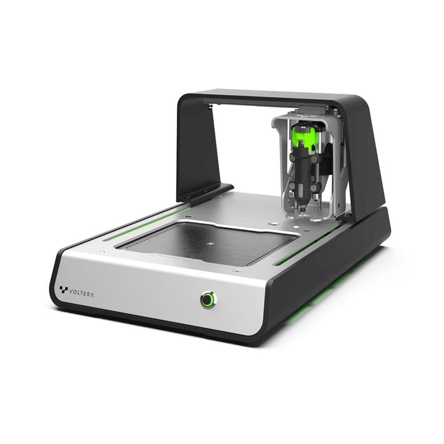
Solder Paste Dispensing and Reflow All-in-One
The Voltera V-One creates two-layer prototype circuit boards on your desk. Gerber files go in, printed circuit boards come out. The dispenser lays down a silver-based conductive ink to print your circuit right before your eyes. Assembling traditional and additive boards is easy with the V-One’s solder paste dispensing and reflow features. Simply mount your board on the print bed and import your Gerber file into Voltera’s software.
No more stencils required
Voltera’s software is designed to be understood easily. From importing your Gerber files to the moment you press print, the software safely walks you through each step.
Compatible with EAGLE, Altium, KiCad, Mentor Graphics, Cadence, DipTrace, Upverter.
Included
V-One PCB printer
V-One dispenser
V-One probe
Nozzle pack
Tip caps
3 x 4" FR1 substrate pack
2 x 3" FR1 substrate pack
Substrate clamps
Thumbscrew pack
Hello World kit
Solder wire
Tweezers
Power supply
Power adapter
Cables
User guides
Downloads
Specifications
V-One Software
Manuals
Safety Datasheets
Technical Datasheets
Voltera CAM file for EAGLE
Substrates and Templates
More Info
Frequently Asked Questions
More from the Voltera community
Technical Specifications
Printing Specifications
Minimum trace width
0.2 mm
Minimum passive size
1005
Minimum pin-to-pin pitch (conductive ink)
0.8 mml
Minimum pin-to-pin pitch (solder paste)
0.5 mml
Resistivity
12 mΩ/sq @ 70 um height
Substrate material
FR4
Maximum board thickness
3 mm
Soldering Specifications
Solder paste alloy
Sn42/Bi57.6/Ag0.4
Solder wire alloy
SnBiAg1
Soldering iron temperature
180-210°C
Print Bed
Print area
135 x 113.5 mm
Max. heated bed temperature
240°C
Heated bed ramp rate
~2°C/s
Footprint
Dimensions
390 x 257 x 207 mm (L x W x H)
Weight
7 kg
Computing Requirements
Compatible operating systems
Windows 7 or higher, MacOS 10.11 or higher
Compatible file format
Gerber
Connection type
Wired USB
Certification
EN 61326-1:2013
EMC requirements
IEC 61010-1
Safety requirements
CE Marking
Affixed to the Voltera V-One printers delivered to European customers
Designed and assembled in Canada.
More technical information
Quickstart
Explore Flexible Printed Electronics on the V-One
Voltera V-One Capabilities Reel
Voltera V-One PCB Printer Walkthrough
Unpacking the V-One
V-One: Solder Paste Dispensing and Reflow All-in-One
Voltera @ Stanford University's Bao Research Group: Robotic Skin and Stretchable Sensors
Voltera @ Princeton: The Future of Aerospace Innovation
Temporary Delay in the Delivery of Unitree Robots
Like many other suppliers, we are currently experiencing delays in the delivery of Unitree robots. A shipment from our supplier is currently held in customs, which has unfortunately led to later-than-planned deliveries for previously placed orders. We are actively working with our supplier to resolve this issue and expect more clarity soon, but at this time, we cannot provide any guarantees.
Additionally, a new shipment is already on its way, though it will take some time to arrive. Since other suppliers are facing similar challenges, switching to a different provider is unlikely to result in a faster solution. Our top priority remains fulfilling existing orders.
If you have any questions or would like to update your order, please do not hesitate to contact our customer service team. We will keep you informed of any further developments.
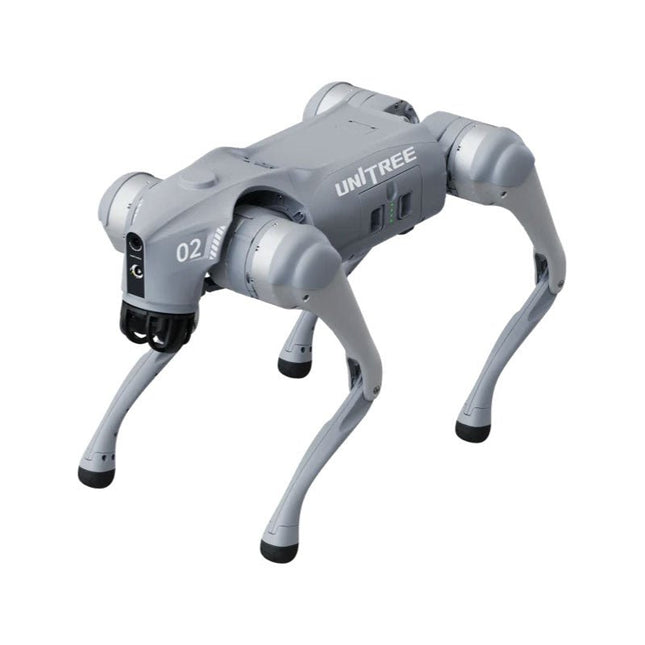
Unitree Go2 series consists of quadruped robots for the research & development of autonomous systems in the fields of human-robot interaction (HRI), SLAM & transportation. Due to the four legs, as well as the 12DOF, this robot can handle a variety of different terrains. The Go2 comes with a perfected drive & power management system, which enables a speed (depending on the version) of up to 3.7 m/s or 11.88 km/h with an operating time of up to 4 hours. Furthermore, the motors have a torque of 45 N.m at the body/thighs and at the knees, which also allow jumps or backflips.
Features
Super Recognition System: 4D LIDAR L1
Max Running Speed: approx. 5 m/s
Peak Joint Torque: approx. 45 N.m
Wireless Module: WiFi 6/Bluetooth/4G
Ultra-long battery Endurance: approx. 2-4 h (long battery life measured in real life)
Intelligent Side-follow System: ISS 2.0
Specifications
Tracking module: Remote-controlled or automatic tracking
Front camera: Image tansmission Resolution 1280x720, FOV 120°, Ultra wide angle lens deliver rich clarity
Front lamp: Brightly lights the way ahead
4D LiDAR L1: 360°x90° omnidirectional ultra-wide-angle scanning allows automatic avoidance with small blind spot and stable operation
12 knee joint motors: Strong and powerful, Beautiful and simple, Brandy new visual experience
Intercom microphone: Effective communication with no scenario restrictions
Self-retracting strap: Easy to carry and load things
More stable, more powerful with advanced devices: 3D LiDAR, 4G ESIM Card, WiFi 6 with Dual-band, Bluetooth 5.2 for stable connection and remote control
Powerful Computing Core: Motion controller, High-performance ARM processor, Improved Al algorithm processor, External ORIN NX/NANO
Smart battery: Standard 8000 mAh battery, Long-endurance 15000 mAh battery, Protection from over-temp, overcharge and short-circuit
Speaker for music play: Listen to music as your pleasure
Unitree Go2 Variants
The Go2 impresses not only with its technical capabilities, but also with a modern and slim design that gives it a futuristic look and makes it a real eye-catcher. The Go2 Air is specially designed for demos and presentations. With its basic features, it offers a solid basis for demonstrating the movement capabilities and functionality of a four-legged robot. Important: The Go2 Air is delivered without a controller. This can be purchased optionally.
With a powerful 8-core high-performance CPU, the Pro and Edu offer impressive computing power required for complex tasks and demanding calculations. This enables faster and more efficient data processing and makes the Pro and Edu a reliable partner for your projects.
From the Edu version onwards, the Go2 is programmable and opens up endless possibilities for developing and researching your own robotics applications. The Go2 is also able to handle a step height of up to 14 cm. This makes it an ideal tool for research, education and entry into the world of robotics.
The Go2 Edu comes with a remote controller that gives you easy and intuitive control. You also get a docking station with impressive computing power of 100 TOPS, which is equipped with powerful AI algorithms and offers you technical support.
Go2 Edu is equipped with a powerful 15000 mAh battery that gives it an impressive runtime of up to 4 hours. This long operating time allows the robot to carry out longer exploration missions and complete demanding tasks.
Model Comparison
Air
Pro
Edu/Edu Plus
Dimensions (standing)
70 x 31 x 40 cm
70 x 31 x 40 cm
70 x 31 x 40 cm
Dimensions (crouching)
76 x 31 x 20 cm
76 x 31 x 20 cm
76 x 31 x 20 cm
Material
Aluminium alloy + High strength engineering plastic
Aluminium alloy + High strength engineering plastic
Aluminium alloy + High strength engineering plastic
Weight (with battery)
about 15 kg
about 15 kg
about 15 kg
Voltage
28~33.6 V
28~33.6 V
28~33.6 V
Peaking capacity
about 3000 W
about 3000 W
about 3000 W
Payload
≈7 kg (MAX ~ 10 kg)
≈8 kg (MAX ~ 10 kg)
≈8 kg (MAX ~ 12 kg)
Speed
0~2.5 m/s
0~3.5 m/s
0~3.7 m/s (MAX ~ 5 m/s)
Max Climb Drop Height
about 15 cm
about 16 cm
about 16 cm
Max Climb Angle
30°
40°
40°
Basic Computing Power
N/A
8-core High-performance CPU
8-core High-performance CPU
Aluminum knee joint motor
12 set
12 set
12 set
Intra-joint circuit (knee)
✓
✓
✓
Joint Heat Pipe Cooler
✓
✓
✓
Range of Motion
Body: −48~48°
Body: −48~48°
Body: −48~48°
Thigh: −200°~90°
Thigh: −200°~90°
Thigh: −200°~90°
Shank: −156°~−48°
Shank: −156°~−48°
Shank: −156°~−48°
Max Torque
N/A
about 45 N.m
about 45 N.m
Super-wide-angle 3D LiDAR
✓
✓
✓
Wireless Vector Positioning Tracking Module
N/A
✓
✓
HD Wide-angle Camera
✓
✓
✓
Foot-end force sensor
N/A
N/A
✓
Basic Action
✓
✓
✓
Auto-scaling strap
N/A
✓
N/A
Upgraded Intelligent OTA
✓
✓
✓
RTT 2.0 Image Transmission
✓
✓
✓
App Basic Remote Control
✓
✓
✓
App Data Viewing
✓
✓
✓
App Graphical Programme
✓
✓
✓
Front Lamp (3 W)
✓
✓
✓
WiFi 6 with Dual-band
✓
✓
✓
Bluetooth 5.2/4.2/2.1
✓
✓
✓
4G Module
N/A
CN/GB
CN/GB
Voice Function
N/A
✓
✓
Music Playback
N/A
✓
✓
ISS 2.0 Intelligent side-follow system
N/A
✓
✓
Intelligent detection and avoidance
✓
✓
✓
Secondary development
N/A
N/A
✓
Manual controller
Optional
Optional
✓
High computing power module
N/A
N/A
Edu: 40 TOPS computing power
Edu Plus: 100 TOPS computing power
NVIDIA Jetson Orin (optional)
Smart Battery
Standard (8000 mAh)
Standard (8000 mAh)
Long endurance (15000 mAh)
Battery Life
1-2 h
1-2 h
2-4 h
Charger
Standard (33.6 V, 3.5 A)
Standard (33.6 V, 3.5 A)
Fast charge (33.6 V, 9 A)
Included
1x Unitree Go2 Pro
1x Unitree Go2 Battery (8000 mAh)
Downloads
Documentation
iOS/Android apps
GitHub
The Whadda 3D Xmas Tree Kit is aimed at hobbyists and beginners who are interested in soldering and electronics. With this DIY kit, you can build a festive LED Christmas tree.
Features
16 flashing red LEDs
Extra green and yellow LEDs provided to customise your tree
Can be hung on and fed through wires
Will operate on 12 V DC (e.g. in cars)
Specifications
Low power consumption
8 mA
Power supply
9 V battery operation (not included)
Dimensions
102 x 88 x 80 mm
Weight
65 g
Downloads
Manual
The X500 V2 ARF Kit is an affordable, lightweight, and robust carbon fiber professional drone kit that is easy to assemble (less than 15 minutes). It comes with the X500 V2 Frame Kit and motors, ESCs, power distribution boards and propellers preinstalled. It is perfectly compatible with various flight controllers such as the Holybro Pixhawk series, Durandal, Pix32 V5, etc. There are numerous improvements compared the previous model.
Specifications
Wheelbase: 500 mm
Motor mount pattern: 16x16 mm
Frame body: 144x144 mm, 2 mm thick
Landing gear height: 215 mm
Space between top and bottom plates: 28 mm
Weight: 610 g
Flight time: ~18 minutes hover with no additional payload. Tested with 5000 mAh battery.
Payload: 1500 g (without battery, 70% throttle)
Battery recommendation: 4S 3000-5000 mAh 20C+ with XT60 Lipo battery (not Included)
Included
X500 V2 Frame Kit
With Preinstalled Items:
4x Motors: Holybro 2216 KV920 Motor (4 pcs) with XT30 Plug
4x ESCs (BLHeli S ESC 20A)
6x 1045 Propellers
Power Distribution Board – XT60 plug for battery & XT30 plug for ESCs & peripherals
Note: Depth camera mount is sold separately.
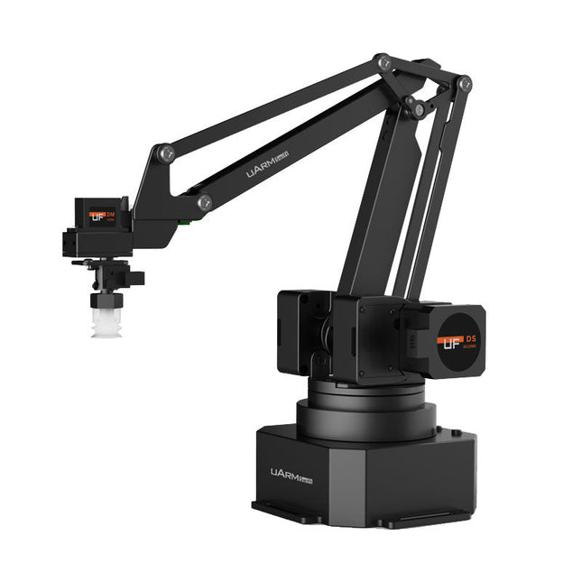
The uArm Swift Pro is a high quality robotic arm that can be used in a wide range of applications. The uArm Swift Pro was developed and optimized for use in education, which means that many packages are already available for open source platforms such as ROS. The uArm Swift Pro has a position repeatability of 0.2 mm and is also equipped with a stepper motor and a 12-bit encoder. These are just a few reasons that make the uArm Swift Pro an excellent choice for educational use. Another great feature is the 3D printing kit that converts the uArm Swift Pro into a 3D printer in less than 1 minute.
The uArm supports the following development platforms/systems:
UFACTORY SDK
Arduino
Python
ROS
GRABCAD
OpenMV
Smartphone App
The smartphone app for iOS is already available in the App Store and enables easy control and monitoring of the robotic arm. The app for Android is in development and will be available soon.
An example of the Machine Vision
The following GIF shows the uArm in combination with the OpenMV Machine Vision Cam M7 and the facial recognition applications that can be implemented in MicroPython.
Specifications
Degrees of Freedom: 4
Repeatability: Up to 0.2 mm
Payload: 500 g
Working Range: 50-320 mm
Positioning Speed: 100 m/s
Position Feedback: 12-bit Encoder
Dimensions: 150 x 140 x 281mm
Weight: 2.2 kg
Included
UFactory uArm Swift Pro Body
Bluetooth & Vacuum Gripper
Downloads
Datasheet
This category offers a wide spectrum of platforms to choose from. They all have different features and you can choose the platform that best suits your needs or project.