YDLIDAR T-mini Pro is a 360-degrees 2D LiDAR based on the principle of ToF. It is equipped with related optics, electricity, and algorithm design to achieve high-precision laser distance measurement, while measuring the distance, the mechanical structure rotates 360 degrees to continuously obtain angle information, thereby realizing 360 degrees scanning distance measurement and outputting point cloud data of the scanning environment.
Features
It adopts the mature ToF detection principle, it can be easy to integrate into the whole device with a small size, bringing the robot a 360° two-dimensional environment with strong stability and high precision.
6-12 Hz self-adaptive scanning frequency, the speed can be adjusted independently according to functional needs. The mechanical structure rotates 360°, continuously obtains angle information, scans and measures in all directions, and outputs point cloud.
Smaller appearance and lower power consumption, which can greatly optimize the spatial structure of application products and are suitable for more scenarios.
The brushless motor operates efficiently and has a longer lifespan of 10,000 hours.
Specifications
Range distance: 0.02-12 m
Range frequency: 4000 Hz
Angle resolution: 0.54 degrees
Scan frequency: 6-12 Hz
Scan angle: 360 degrees
Interface: UART
Applications
Robot navigation and obstacle avoidance
Robot ROS teaching and research
Regional security
Environmental scanning and 3D reconstruction
Navigation and obstacle avoidance of home service robots/ robot vacuum cleaners
Downloads
Datasheet
Manual
Development Manual
SDK
Tool
ROS
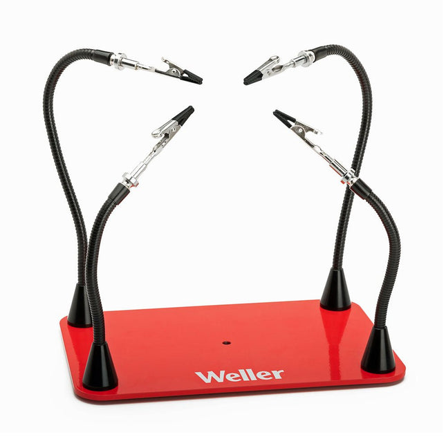
Free up your hands and secure and protect your soldering projects with Weller's Helping Hands with 4 Magnetic Arms. Enjoy adjustable and flexible positions with magnetic gooseneck arms with alligator clamps that are easily positionable for multiple configurations. Applications Hobby Home repair Drone Audio repair Joining wires Engraving Jewelry making Electronics Specifications Dimensions (Base) 152 x 229 mm (6 x 9') Length (Arms) 2 arms: 216 mm (8.5')2 arms: 317 mm (12.5')
Get ready to start soldering kits thanks to this all-inclusive tool set!Want to start soldering gadgets, or do you want to fix some home appliances, but you don't know what tools to get? Then this is the perfect set for you! It includes all the basic tools and practical necessities to start your journey as an electronics engineer or maker!Included
AS19: Silicone soldering mat (350 x 250 mm)
Lead-free solder Sn 99.3% – Cu 0.7% with dispenser (1.0 mm, 15 g)
Desolder: Desoldering braid
Stand20: Universal soldering iron stand
VT281: Side cutter pliers
VTD7: Powerful desoldering pump
VTHHN: Helping hand with magnifier
VTSI30C: High-Q ceramic soldering iron 30 W / 220-240 VAC
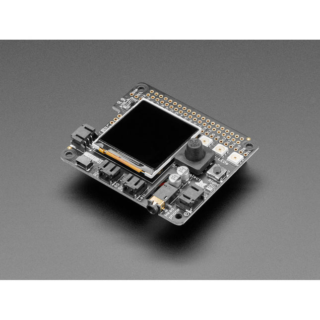
Can you use the SparkFun Top pHAT to prototype machine learning on your Raspberry Pi 4, NVIDIA Jetson, Google Coral or another single-board computer? Indubitably! The SparkFun Top pHAT supports machine learning interactions, including voice control with onboard microphones & speaker, graphical display for camera control feedback, and uninhibited access to the RPi camera connector. Additionally, you can use the programmable buttons, joystick, and RGB LED for user-defined I/O, dynamic system interaction, or system status displays.
Can you use it as an interface to introduce your project to the SparkFun Qwiic ecosystem? Indeed! In addition to all the previous features, we have also included a Qwiic connector to allow easy integration over I²C. Billions of combinations of Qwiic-enabled boards are available to you to expand upon the capabilities of the SparkFun Top pHAT.
With all the I/O interaction on this board and the lack of soldering needed to get up and running, the SparkFun Top pHAT is the fundamental machine learning add-on for Raspberry Pi or any 2x20 GPIO SBC!
Features
A Raspberry Pi pHAT that focuses on user interaction with an SBC/RPi.
Support for machine learning interactions
Voice control (microphones, speaker)
Graphical display on 2.4' colour TFT
Two Programmable buttons for user-defined I/O
Programmable Joystick – for dynamic/interaction with the system (GUI menus, robot driving).
Programmable RGB LEDs – for system status, display.
Does not inhibit access to RPi camera or display connector
On/Off switch for RPi.
Supports access to the SparkFun Qwiic ecosystem
Intended to be at the top of a pHAT stack - no pins for stacking on top of this board. It’s the Top pHAT!
The Power Delivery Board uses a standalone controller to negotiate with the power adapters and switch to a higher voltage other than just 5V. This uses the same power adapter for different projects rather than relying on multiple power adapters to provide different output; it can deliver the board as part of SparkFun’s Qwiic connect system, so you won’t have to do any soldering to figure out how things are oriented.
The SparkFun Power Delivery Board takes advantage of the power delivery standard using a standalone controller from STMicroelectronics, the STUSB4500. The STUSB4500 is a USB power delivery controller that addresses sink devices. It implements a proprietary algorithm to negotiate a power delivery contract with a source (i.e. a power delivery wall wart or power adapter) without the need for an external microcontroller. However, you will need a microcontroller to configure the board. PDO profiles are configured in an integrated non-volatile memory. The controller does all the heavy lifting of power negotiation and provides an easy way to configure over I²C.
To configure the board, you will need an I²C bus. The Qwiic system makes it easy to connect the Power Delivery board to a microcontroller. Depending on your application, you can also connect to the I²C bus via the plated through SDA and SCL holes.
Features
Input and output voltage range of 5-20V
Output current up to 5A
Three configurable power delivery profiles
Auto-run Type-C™ and USB PD sink controller
Certified USB Type-C™ rev 1.2 and USB PD rev 2.0 (TID #1000133)
Integrated VBUS voltage monitoring
Integrated VBUS switch gate drivers (PMOS)
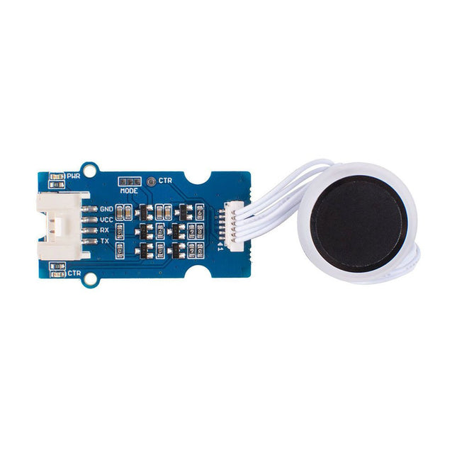
The Grove Capacitive Fingerprint Scanner/Sensor is based on the KCT203 Semiconductor fingerprint recognition module, including a high-performance MCU, a vertical RF push-type fingerprint sensor, and a touch sensing device.
This module features many advantages such as small size, small fingerprint template, low power consumption, high reliability, fast fingerprint recognition, etc. In addition, it is worth mentioning that there is a lovely RGB light around this module to indicate whether the fingerprint recognition is successful.
The system is equipped with a high-performance fingerprint algorithm, and the self-learning function is remarkable. After each successful fingerprint recognition, the latest challenge feature values can be integrated into the fingerprint database to continuously improve the fingerprint features, making the experience better.
Applications
Fingerprint lock devices: door locks, safes, steering wheel locks, padlocks, gun locks, etc.
Fingerprint sign-in, access control system
Specifications
CPU
GD32
Fingerprint Template Storage
Max. 100
Connector
Grove UART
Sensor Resolution
508 DPI
Sensor Pixel
160x160
False Rejection Rate
<1%
False Acceptance Rate
<0.005%
Match Response Time(1:N Mode)
<350ms
Match Response Time(1:1 Mode)
<7ms
Sensor Size
Φ14.9mm
Frame Size
Φ 19mm
Power Consumption
Full speed: ≤40 mA; Sleep: ≤12 uA
Operating Voltage
3.3 V / 5 V
Operating Temperature
-20 ~ 70 ℃
ESD Protection
Non-contact 15 KV, contact 8 KV
Included
1x KCT203 Semiconductor fingerprint recognition module
1x Sensor cable
1x Grove cable
1x Grove driver board
Documentations
Grove Capacitive Fingerprint Scanner/Sensor eagle file
Grove Capacitive Fingerprint Scanner/Sensor code
Wiki
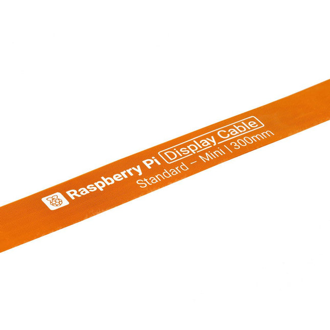
Raspberry Pi 5 provides two four-lane MIPI connectors, each of which can support either a camera or a display. These connectors use the same 22-way, 0.5 mm-pitch “mini” FPC format as the Compute Module Development Kit, and require adapter cables to connect to the 15-way, 1 mm-pitch “standard” format connectors on current Raspbery Pi camera and display products.These mini-to-standard adapter cables for cameras and displays (note that a camera cable should not be used with a display, and vice versa) are available in 200 mm, 300 mm and 500 mm lengths.
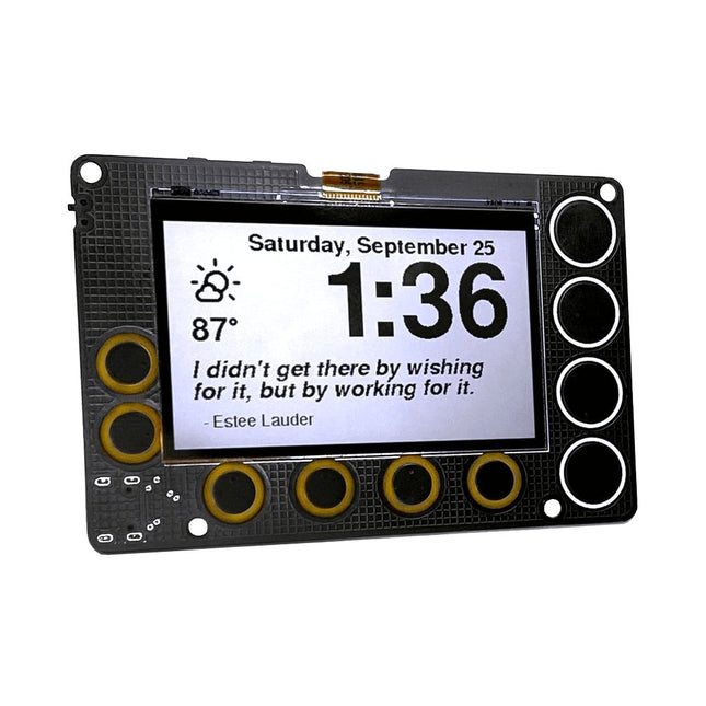
A low-power, open source, 2.7-inch IoT display powered by an ESP32-S2 module and featuring SHARP's Memory-in-Pixel (MiP) screen technology
The Newt is a battery-powered, always-on, wall-mountable display that can go online to retrieve weather, calendars, sports scores, to-do lists, quotes…really anything on the Internet! It is powered by an ESP32-S2 microcontroller that you can program with Arduino, CircuitPython, MicroPython, or ESP-IDF. It's perfect for makers:
Sharp’s Memory-in-Pixel (MiP) technology avoids the slow refresh times associated with E-Ink displays
A real-time clock (RTC) was added to support timers and alarms
The Newt was designed with battery operation in mind; every component on the board was chosen for its ability to operate at low power.
Newt was designed to operate 'untethered,' which means it can be mounted in places where a power cord would be inconvenient, for example a wall, refrigerator, mirror, or dry-erase board. With the optional stand, desks, shelves, and nightstands are also good options.
Newt is open source, and all design files and libraries are available for review, use, and modification. However, doing that is not required. Each Newt is delivered with working code with the following features:
Current weather details
Hourly and daily weather forecast
Alarm
Timer
Inspirational quotes
Air-quality forecast
Habit calendar
Pomodoro timer
Oblique Strategy cards
Only following the Wi-Fi provisioning instructions is needed to get started. No app downloads are required.
Specifications
Display
Sharp Memory LCD
Screen Size
2.7 inch
Resolution
240 x 400
Deep Sleep Current
30 uA
Refresh Rate
< 0.001 s
Periodic Screen Refresh Required
No
Input Buttons
10 capacitive pads, 1 push button
RTC included
Yes
Speaker included
Yes
Power Input
USB Type-C
Battery included
No
Programming Languages
Arduino, CircuitPython, ESP IDF, MicroPython
Dimensions
91 x 61 x 9 mm
Microcontroller
Espressif ESP32-S2-WROVER Module with 4 MB flash and 2 MB PSRAM
Wi-Fi capable
Supports Arduino, MicroPython, CircuitPython, and ESP-IDF
Deep sleep current as low as 25 μA
Display
2.7-inch, 240 x 400 pixel MiP LCD
Capable of delivering high-contrast, high-resolution, low-latency content with ultra-low power consumption
Reflective mode leverages ambient light to eliminate the need for a backlight
Time Keeping, Timers, and Alarms
Micro Crystal RV-3028-C7 RTC
Optimized for extreme low-power consumption (45 μA)
Able to simultaneously manage a periodic timer, a countdown timer, and an alarm
Hardware interrupt for timers and alarms
43 bytes of non-volatile user memory, 2 bytes of user RAM
Separate UNIX time counter
Buzzer
Speaker/buzzer with mini class-D amplifier on DAC output A0 can play tones or lo-fi audio clips
User Input
Power switch
Two programmable tactile buttons for Reset and Boot
10 capacitive touchpads
Power
Newt is designed to operate for one to two months between charges using a 500 mAH LiPo battery. The exact run time varies. (Heavy Wi-Fi use, in particular, will reduce battery charge more quickly.)
USB Type-C connector for programming, power, and charging
Low-quiescence voltage regulator (TOREX XC6220) that can output 1 A of current and operate as low as 8 μA.
JST connector for a Lithium-Ion battery
Battery-charging circuity (MCP73831)
Low-battery indicator (1 μA quiescence current)
Software
Newt hardware is compatible with open-source Arduino libraries for ESP32-S2, Adafruit GFX (fonts), Adafruit Sharp Memory Display (display writing), and RTC RV-3028-C7 (RTC)
Arduino libraries and sample programs are under development and will be available in our GitHub repository before launch
CircuitPython libraries and registration are on the roadmap, with the development of a CircuitPython library for the RV-3028 real-time clock as a key dependency
Included
Phambili Newt – Fully assembled with pre-loaded firmware
Laser-cut desktop stand
Mini-magnet feet
Required screws
Support & Documentation
Full instructions for use
GitHub: Arduino Library and Codebase
GitHub: Board schematics
Videos of prototypes or demos (build tracked on Hackaday)
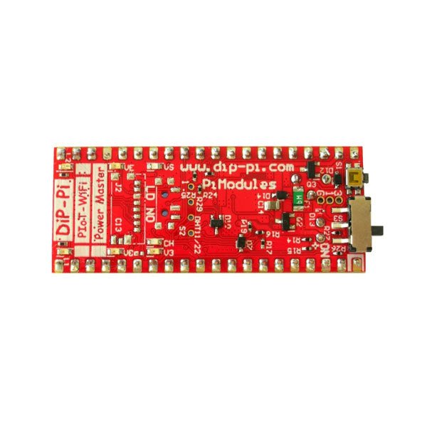
The DiP-Pi Power Master is an Advanced Powering System with embedded sensors interfaces that cover most of possible needs for application based on Raspberry Pi Pico. It can supply the system with up to 1.5 A @ 4.8 V delivered from 6-18 VDC on various powering schemes like Cars, Industrial plant etc., additionally to original micro-USB of the Raspberry Pi Pico. It supports LiPo or Li-Ion Battery with Automatic Charger as also automatic switching from cable powering to battery powering or reverse (UPS functionality) when cable powering lost. Extended Powering Source (EPR) is protected with PPTC Resettable fuse, Reverse Polarity, as also ESD.
The DiP-Pi Power Master contains Raspberry Pi Pico embedded RESET button as also ON/OFF Slide Switch that is acting on all powering sources (USB, EPR or Battery). User can monitor (via Raspberry Pi Pico A/D pins) battery level and EPR Level with PICO’s A/D converters. Both A/D inputs are bridged with 0402 resistors (0 OHM) therefore if for any reason user needs to use those Pico pins for their own application can be easy removed. The charger is automatically charging connected battery (if used) but in addition user can switch charger ON/OFF if their application needs it. DiP-Pi Power Master can be used for cable powered systems, but also for pure Battery Powered System with ON/OFF. Each powering source status is indicated by separate informative LEDs (VBUS, VSYS, VEPR, CHGR, V3V3).
User can use any capacity of LiPo or Li-Ion type; however, must take care to use PCB protected batteries with max discharge current allowed of 2 A. The embedded battery charger is set to charge battery with 240 mA current. This current is set by resistor so if user need more/less can himself to change it.
In Addition to all above features DiP-Pi Power Master is equipped with embedded 1-wire and DHT11/22 sensors interfaces. Combination of the extended powering, battery, and sensors interfaces make the DiP-Pi Power Master ideal for applications like data logger, plants monitoring, refrigerators monitoring etc.
DiP-Pi Power Master is supported with plenty of ready to use examples written in Micro Python or C/C++.
Specifications
General
Dimensions 21 x 51 mm
Raspberry Pi Pico pinout compatible
Independent Informative LEDs (VBUS, VSYS, VEPR, CHGR, V3V3)
Raspberry Pi Pico RESET Button
ON/OFF Slide Switch acting on all powering sources (USB, EPR, Battery)
External Powering 6-18 V DC (Cars, Industrial Applications etc.)
External Power (6-18 VDC) Level Monitoring
Battery Level Monitoring
Inverse Polarity Protection
PPTC Fuse Protection
ESD Protection
Automatic Battery Charger (for PCB protected LiPo, Li-Ion – 2 A Max) Automatic/User Control
Automatic Switch from Cable Powering to Battery Powering and reverse (UPS Functionality)
Various powering schemes can be used at the same time with USB Powering, External Powering and Battery Powering
1.5 A @ 4.8 V Buck Converter on EPR
Embedded 3.3 V @ 600mA LDO
Embedded 1-wire Interface
Embedded DHT-11/22 Interface
Powering Options
Raspberry Pi Pico micro-USB (via VBUS)
External Powering 6-18 V (via dedicated Socket – 3.4/1.3 mm)
External Battery
Supported Battery Types
LiPo with protection PCB max current 2A
Li-Ion with protection PCB max current 2A
Embedded Peripherals and Interfaces
Embedded 1-wire interface
Embedded DHT-11/22 Interface
Programmer Interface
Standard Raspberry Pi Pico C/C++
Standard Raspberry Pi Pico Micro Python
Case Compatibility
DiP-Pi Plexi-Cut Case
System Monitoring
Battery Level via Raspberry Pi Pico ADC0 (GP26)
EPR Level via Raspberry Pi Pico ADC1 (GP27)
Informative LEDs
VB (VUSB)
VS (VSYS)
VE (VEPR)
CH (VCHR)
V3 (V3V3)
System Protection
Direct Raspberry Pi Pico Hardware Reset Button
ESD Protection on EPR
Reverse Polarity Protection on EPR
PPTC 500 mA @ 18 V fuse on EPR
EPR/LDO Over Temperature protection
EPR/LDO Over Current protection
System Design
Designed and Simulated with PDA Analyzer with one of the most advanced CAD/CAM Tools – Altium Designer
Industrial Originated
PCB Construction
2 ozcopper PCB manufactured for proper high current supply and cooling
6 mils track/6 mils gap technology 2 layers PCB
PCB Surface Finishing – Immersion Gold
Multi-layer Copper Thermal Pipes for increased System Thermal Response and better passive cooling
Downloads
Datasheet
Datasheet
LuckFox Pico Mini is a compact Linux micro development board based on the Rockchip RV1103 chip, providing a simple and efficient development platform for developers. It supports a variety of interfaces, including MIPI CSI, GPIO, UART, SPI, I²C, USB, etc., which is convenient for quick development and debugging.
Features
Single-core ARM Cortex-A7 32-bit core with integrated NEON and FPU
Built-in Rockchip self-developed 4th generation NPU, features high computing precision and supports int, int8, and int16 hybrid quantization. The computing power of int8 is 0.5 TOPS, and up to 1.0 TOPS with int4
Built-in self-developed third-generation ISP3.2, supports 4-Megapixel, with multiple image enhancement and correction algorithms such as HDR, WDR, multi-level noise reduction, etc.
Features powerful encoding performance, supports intelligent encoding mode and adaptive stream saving according to the scene, saves more than 50% bit rate of the conventional CBR mode so that the images from camera are high-definition with smaller size, double the storage space
Built-in RISC-V MCU supports low power consumption and fast start-up, supports 250 ms fast picture capture and loading Al model library at the same time to realize face recognition "in one second"
Built-in 16-bit DRAM DDR2, which is capable of sustaining demanding memory bandwidths
Integrated with built-in POR, audio codec and MAC PHY
Specifications
Processor
ARM Cortex-A7, single-core 32-bit CPU, 1.2 GHz, with NEON and FPU
NPU
Rockchip 4th-gen NPU, supports int4, int8, int16; up to 1.0 TOPS (int4)
ISP
Third-gen ISP3.2, up to 4 MP input at 30fps, HDR, WDR, noise reduction
RAM
64 MB DDR2
Storage
128 MB SPI NAND Flash
USB
USB 2.0 Host/Device via Type-C
Camera Interface
MIPI CSI 2-lane
GPIO Pins
17 GPIO pins
Power Consumption
Low power, RISC-V MCU for fast startup
Dimensions
28 x 21 mm
Downloads
Wiki
This kit is based on ESP32 and LoRa. The ESP32 3.5" display is the console for the system, it receives the LoRa message from LoRa moisture sensors (support up to 8 sensors in the default firmware), and send control commands to LoRa 4-channel MOSFET (2 4-channel MOSFET supported, with totally 8 channels), to control the connected valves open/close, and thus to control the irrigation for multiple points.
Features
Ready to use: Firmware are pre-programmed for all the modules before shipping, the user can only power them up and set the ID to the console, and start to use. Suitable for none-programmers, in 3 minutes to create filed application.
With Lora wireless connection: The monitor & control range can be up to few kilometer, suitable for garden/small farm.
Soil moisture sensor with good corrosion resistance, can be used at least half an year with 2 AAA battery.
Easy to install: Compares to cheap solution with wires, which is hard to implement in files application, there the connection wires do not needed, the whole installation clean and easy; The valves can be connected Lora MOSFET easily.
Hardware & Software Open: To study Lora & FreeRTOS. The ESP32 display console/Lora Soil Moisture Sensor/LoRa MOSFE are all programmed with Arduino. For programmers/engineers, can development further more specialized application.
Based on ESP32, with WiFi connection, the console can also access to internet, the create much more applications including the moisture data updating to internet for remote monitor, and remote control with MQTT.
Included
1x ESP32 3.5' Display (without camera)
1x Lora Expansion for ESP32 Display
2x Lora Moisture Sensor
1x Lora 4-channel MOSFET
1x 12 V Power Supply
Water Pipe (5 m)
1x 1-input & 4-output Pipe Joint
Downloads
Instructable: Soil Monitoring & Irrigation with LoRa
GitHub
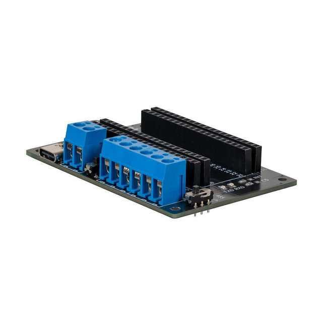
This expansion board allows you to add an RS485 and a CAN interface to a Raspberry Pi Pico.
The board also offers the option of operating it either via a standard USB-C connection with 5 V or via a screw terminal that accepts a voltage of 6 to 12 V. The voltage applied to the screw terminal is reduced to 5 V by a voltage converter integrated on the board.
Features
Power can be supplied via a USB-C connection with 5 V or via a screw terminal that draws between 6 and 12 V. In the latter case, a built-in voltage converter reduces the voltage to 5 V.
To increase the versatility and range of functions, the connection pins of the Raspberry Pi Pico have been routed to the outside.
The expansion board also offers the option of communication via the RS485 and CAN interfaces.
Specifications
CAN Interface
SPI, CAN
RS485 Interface
Serial, RS485
Power supply
5 V DC (USB-C)
Screw terminal
6-12 V DC
Logic level
3.3 V
Terminating resistor CAN
120 Ω (can be activated and deactivated as required)
Terminating resistor RS485
120 Ω (can be activated and deactivated as required)
The SDS011 sensor determines the dust particle concentration in the air using the scattered light method.
The USB-UART adapter also allows the sensor to be read out directly via USB port on a computer.
Specifications
Interface
UART (3.3 V level)
Resolution
0.3 µg/m3
Response time
< 10s
Other feature
Integrated fan
Current in idle
< 4 mA
Supply current
70 mA
Operating voltage
5 V
Dimensions
70 x 70 x 24 mm
Weight
70 g
Included
1x SDS011 dust sensor
1x Connection cable
1x USB-UART adapter
Downloads
Datasheet
Manual
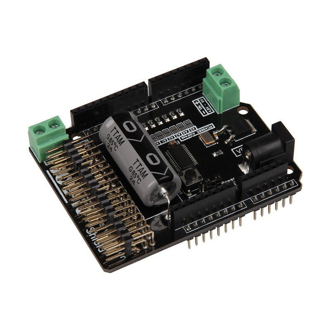
The Motorino board is an extension-board to control and use up to 16 PWM-controlled 5V-Servo-motors. The included clock generator ensures a very precise PWM signal and a very precise positioning. The board has 2 inputs for voltage from 4.8 V to 6 V which can be used for up to 11 A. With this input, a perfect power supply is always guaranteed and even bigger projects are no problem. The supply runs directly over the Motorino which provides a connection for voltage, ground and control. With the build in capacitor, the voltage is buffered which prevents a sudden voltage-drop at a high load. But there is also the possibility to connect another capacitor. The control and the programing can be done, as usual, with the Arduino. Manuals and code examples allows a quick introduction for beginners. Special features 16 Channels, own clock generator Input 1 Coaxial power connector 5.5 / 2.1 mm, 4.8-6 V / 5 A max Input 2 Screw-terminal, 4.8-6 V / 6 A max Communication 16 x PWM Compatible with Arduino Uno, Mega and may more microcontroller with Arduino compatible pinout Dimensions 69 x 24 x 56 mm Scope of supply Board, Manual, Retail package
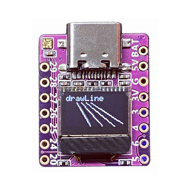
Arduino, MicroPython, and CircuitPython-compatible compact development board powered by Raspberry Pi RP2040
RP2040-0.42LCD is a high-performance development board with integrated 0.42" LCD (70x40 resolution) with flexible digital interfaces.
It incorporates Raspberry Pi's RP2040 microcontroller chip. The RP2040 features a dual-core Arm Cortex-M0+ processor clocked at 133 MHz with 264 KB internal SRAM and 2 MB flash storage.
Specifications
SoC
Raspberry Pi RP2040 dual-core Cortex-M0+ microcontroller at up to 125 MHz, with 264 KB SRAM
Storage
2 MB SPI flash
Display
0.42-inch OLED
USB
1x USB Type-C port for power and programming
Expansion
– Qwiic I²C connector– 7-pin and 8-pin headers with up to 11x GPIOs, 2x SPI, 2x I²C, 4x ADC, 1x UART, 5 V, 3.3 V, VBAT, GND
Misc
– Reset and Boot buttons– RGB LED, power LED
Power supply
– 5 V via USB-C port or Vin– VBAT pin for battery input– 3.3 V regulator with 500 mA peak output
Dimensions
23.5 x 18 mm
Weight
2.5 g
Downloads
GitHub
Features
1.54" IPS TFT display with 240x240 resolution that can show text or video
Stereo speaker ports for audio playback - either text-to-speech, alerts or for creating a voice assistant.
Stereo headphone out for audio playback through a stereo system, headphones, or powered speakers.
Stereo microphone input - perfect for making your very own smart home assistants
Two 3-pin JST STEMMA connectors that can be used to connect more buttons, a relay, or even some NeoPixels!
STEMMA QT plug-and-play I2C port can be used with any of Adafruits 50+ I2C STEMMA QT boards or can be used to connect to Grove I²C devices with an adapter cable.
5-Way Joystick + Button for user interface and control.
Three RGB DotStar LEDs for colorful LED feedback.
The STEMMA QT port means you can attach heat image sensors like the Panasonic Grid-EYE or MLX90640. Heat-Sensitive cameras can be used as a person detector, even in the dark! An external accelerometer can be attached for gesture or vibration sensing such as machinery/industrial predictive maintenance projects
Please note: A Raspberry Pi 4 is not included.
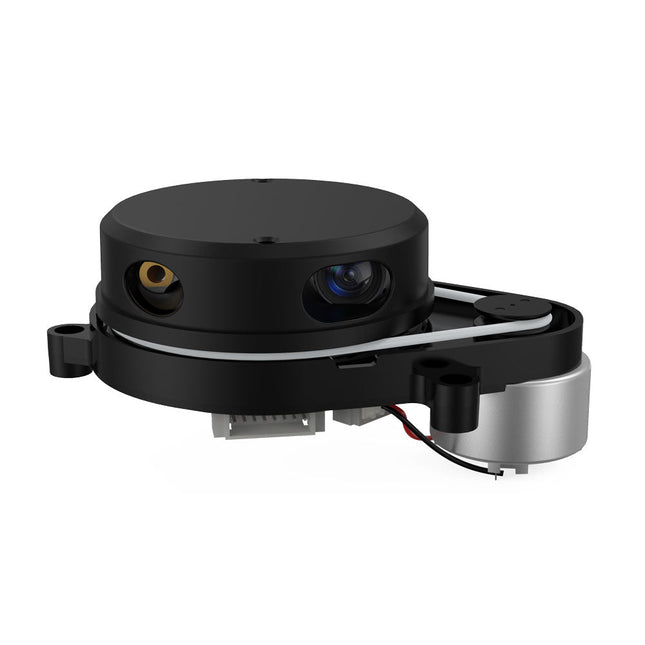
YDLIDAR X4PRO is a 360 degrees two-dimensional rangefinder. Based on the principle of triangulation, it is equipped with related optics, electricity, and algorithm design to achieve high-frequency and high- accuracy distance measurement. The mechanical structure rotates 360 degrees to continuously output the angle information as well as the point cloud data of the scanning environment while ranging.
Features
360 degrees omnidirectional scanning ranging distance measurement
Small distance error, stable performance and high accuracy
Wide ranging distance
Strong resistance to ambient light interference
Low power consumption, small size and long service life
Laser power meets Class I laser safety standards
Adjustable motor speed, scanning frequency is 6~12 Hz
High-speed ranging, ranging frequency up to 5 kHz
Applications
Robot navigation and obstacle avoidance
Robot ROS teaching and research
Regional security
Environmental scanning and 3D reconstruction
Navigation and obstacle avoidance of robot vacuum cleaner/ROS Learning robot
Specifications
Range Frequency
5000 Hz
Scan Frequency
6-12 Hz
Range Distance
0.12 10 m
Scan Angle
360°
Angle Resolution
0.43-0.85°
Dimensions
110.6 x 71.1 x 52.3 mm
Downloads
Datasheet
User Manual
Development Manual
SDK
Tool
ROS
This camera adopts binocular structured light 3D imaging technology to obtain depth images and realize the function of depth information modeling. It is equipped with a dedicated depth computing chip and is specially optimized for robot obstacle avoidance.
The camera is compact in size, easy to integrate, with USB2.0 standard output interface, providing users with a high degree of flexibility. It can be adapted to complex environments such as all-black environment, indoors with strong light or weak light, backlight or smooth light, even semi-outdoors, which has a wide range of applications.
Features
Offers 1280 x 920 high-resolution image output
Uses the binocular structured light 3D imaging technology
Fearless ambient light interference
Deep calculation processors use high-performance dedicated chips
USB2.0 standard output interface
Specifications
Detection distance: 20-250 cm
Accuracy Error: <1.5 cm
Resolution: 1280 x 920 Pixel
HFOV: 78 ±3°
VFOV: 60 ±3°
Power: 1.5 W
Active Light Source: Spectrum: 830-850 nm | Power: <1.5 W
Dust-proof and Waterproof: IP65
ESD: Contact Discharge: ±8 KV | Antiaircraft: ±12 KV
Interface: USB2.0
Operating Temperature: -10~50°C
Operating Humidity: 0~80 RH
Storage Temperature: -20~80°C
Weight: 96 g
Downloads
Datasheet
User Manual
Development Manual
SDK
Tool
ROS
After power on, YDLIDAR G4 start rotating and scanning the environment around it. The scanning distance is 16 m and the device offers a scanning rate of 9,000 times per second.
It makes detailed examinations of its environment and can locate the smallest of objects surrounding it. Featuring a high-precision brushless motor and encoder disc mounted on bearings, it rotates smoothly and has a service life of up to 500,000 hours of operation.
The G4 is an inexpensive solution for projects that require obstacle detection, obstacle avoidance, and/or simultaneous localization and mapping (SLAM). All YDLIDAR products are ROS ready.
Features
360 degree 2D range scanning
Stable performance, high precision
16 m range
Strong resistance to environmental light interference
Brushless motor drive, stable performance
FDA Laser safety standard Class I
360 degree omnidirectional scanning, 5-12 Hz adaptive scanning frequency
OptoMagnetic technology
Wireless data communication
Scanning rate of 9000 Hz
Downloads
Datasheet
User Manual
Development Manual
SDK
Tool
ROS
The SparkFun Thing Plus Matter is the first easily accessible board of its kind that combines Matter and SparkFun’s Qwiic ecosystem for agile development and prototyping of Matter-based IoT devices. The MGM240P wireless module from Silicon Labs provides secure connectivity for both 802.15.4 with Mesh communication (Thread) and Bluetooth Low Energy 5.3 protocols. The module comes ready for integration into Silicon Labs' Matter IoT protocol for home automation.
What is Matter? Simply put, Matter allows for consistent operation between smart home devices and IoT platforms without an Internet connection, even from different providers. In doing so, Matter is able to communicate between major IoT ecosystems in order to create a single wireless protocol that is easy, reliable, and secure to use.
The Thing Plus Matter (MGM240P) includes Qwiic and LiPo battery connectors, and multiple GPIO pins capable of complete multiplexing through software. The board also features the MCP73831 single-cell LiPo charger as well as the MAX17048 fuel gauge to charge and monitor a connected battery. Lastly, a µSD card slot for any external memory needs is integrated.
The MGM240P wireless module is built around the EFR32MG24 Wireless SoC with a 32-bit ARM Cortext-M33 core processor running at 39 MHz with 1536 kb Flash memory and 256 kb RAM. The MGM240P works with common 802.15.4 wireless protocols (Matter, ZigBee, and OpenThread) as well as Bluetooth Low Energy 5.3. The MGM240P supports Silicon Labs' Secure Vault for Thread applications.
Specifications
MGM240P Wireless Module
Built around the EFR32MG24 Wireless SoC
32-bit ARM-M33 Core Processor (@ 39 MHz)
1536 kB Flash Memory
256 kB RAM
Supports Multiple 802.15.4 Wireless Protocols (ZigBee and OpenThread)
Bluetooth Low Energy 5.3
Matter-ready
Secure Vault Support
Built-in Antenna
Thing Plus Form-Factor (Feather-compatible):
Dimensions: 5.8 x 2.3 cm (2.30 x 0.9')
2 Mounting Holes:
4-40 screw compatible
21 GPIO PTH Breakouts
All pins have complete multiplexing capability through software
SPI, I²C and UART interfaces mapped by default to labeled pins
13 GPIO (6 labeled as Analog, 7 labeled for GPIO)
All function as either GPIO or Analog
Built-in-Digital to Analog Converter (DAC)
USB-C Connector
2-Pin JST LiPo Battery Connector for a LiPo Battery (not included)
4-Pin JST Qwiic Connector
MC73831 Single-Cell LiPo Charger
Configurable charge rate (500 mA Default, 100 mA Alternate)
MAX17048 Single-Cell LiPo Fuel Gauge
µSD Card Slot
Low Power Consumption (15 µA when MGM240P is in Low Power Mode)
LEDs:
PWR – Red Power LED
CHG – Yellow battery charging status LED
STAT – Blue status LED
Reset Button:
Physical push-button
Reset signal can be tied to A0 to enable use as a peripheral device
Downloads
Schematic
Eagle Files
Board Dimensions
Hookup Guide
Datasheet (MGM240P)
Fritzing Part
Thing+ Comparison Guide
Qwiic Info Page
GitHub Hardware Repo
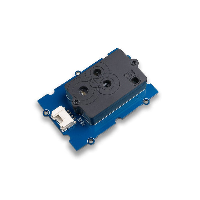
The Grove SCD30 is an Arduino-compatible 3-in-1 environmental sensor for precise CO₂, temperature, and humidity measurements. Powered by the Sensirion SCD30 and advanced Non-Dispersive Infrared (NDIR) technology, it delivers high accuracy across a wide measurement range. The sensor also determines humidity and temperature through smart algorithms that model and compensate for external heat sources.
Features
NDIR CO2 sensor technology: embedded with Sensirion SCD30
Multi-function: Integrates temperature and humidity sensor on the same sensor module
High precision and wide measurement accuracy: ±(30 ppm + 3%) between 400 ppm to 10000 ppm
Superior stability: Dual-channel detection
Easy project operation: Digital interface I²C, Breadboard-friendly, Grove-compatible
Best performance-to-price ratio
Application Ideas
Air Purifier
Environmental Monitoring
Plant Environmental Monitoring system
Arduino weather station
Unlock your inner Mozart with Piano HAT, a mini musical companion for your Raspberry Pi!
Piano HAT is inspired by Zachary Igielman's PiPiano and made with his blessing. It has taken his fabulous idea for a dinky piano add-on for the Raspberry Pi, made it touch-sensitive and added barrels of our trademark Pimoroni polish.
Play music in Python, control software synths on your Pi, and take control of hardware synthesizers!
Features
16 capacitive touch pads (link each to their own Python function!)
13 piano keys (a full octave)
Octave up/down buttons
Instrument cycle button (great for use with synthesizers)
16 bright white LEDs (let them light automagically, or take control with Python)
2x Microchip CAP1188 capacitive touch driver chips
Use it to control software or hardware synths over MIDI
Compatible with all 40-pin header Raspberry Pi models
Comes fully assembled
Downloads
Python library
Pinout