The M12 mount lens (12 MP, 2.7 mm) is ideal for use with the Raspberry Pi HQ Camera Module, offering sharp and detailed imaging for a wide range of applications.
The JOY-iT Explorer 700 Expansion Board for Raspberry Pi expansion board has the following functions:
Pin-Header to put directly on the Raspberry Pi B+, 2B, 3B or 4B
UART interface: connect easily UART modules like for example RS232, RS485, USB to UART (TTL-cable)
AD/DA IO interface: connected cable via screws definable
1-WIRE interface: to connect a 1-WIRE device
Sensor interface: digital and analogue sensors can be connected
0.96 inch OLED display: SSD1306 Driver, 128 x 64 Pixel, SPI interface
Buzzer
USB to UART, converter with CP2102 chipset (mini USB-Port)
PCF8591: 8-bit analog / digital converter, I²C interface
BMP180: sensor for atmospheric pressure, temperature and height over normal zero, I²C interface
PCF8574: I/O Chip for I²C interface
DS3231: high precision RTC chip, I²C interface
Power LED
Programmable LED
Joystick
LFN0038K IR infrared receiver
Interfaces
UART, AD/DA: connected cables can be fixed with screws, 1-Wire, Sensor
Display
0.96“ OLED Display (SSD1306 Driver, 128x64 Pixel)
Dimensions
85 mm x 56 mm x 17 mm
Weight
30 g
For more information, check out the user manual here.
Multi-tool for Building, Analyzing, and Hacking USB Devices
Cynthion is an all-in-one tool for building, testing, monitoring, and experimenting with USB devices. Built around a unique FPGA-based architecture, Cynthion’s digital hardware can be fully customized to suit the application at hand. As a result, it can act as a no-compromise High-Speed USB protocol analyzer, a USB research multi-tool, or a USB development platform.
Out-of-the-box, Cynthion acts as a USB protocol analyzer capable of capturing and analyzing traffic between a host and any Low-, Full-, or High-Speed ("USB 2.0") USB device. It works seamlessly with the open-source analysis software Packetry.
Combined with the LUNA gateware and Facedancer libraries, Cynthion becomes a versatile USB research and development tool. Facedancer makes it quick and easy to create or experiment with real USB devices—not just emulations—even if you don’t have experience with digital hardware design, HDL, or FPGA architecture!
Features
Cynthion is a fully reconfigurable test instrument that provides all the hardware, gateware, firmware, and software you need to work with—and, indeed, tob master-USB. Below are a few of the challenges to which you can apply your Cynthion:
Protocol analysis for Low-, Full-, and High-speed USB: Cynthion provides everything you need for passive USB monitoring. With the Packetry USB analysis software, Cynthion provides everything you need for passive USB monitoring.
Creating your own Low-, Full-, or High-speed USB device: LUNA provides Amaranth gateware that allows you to create USB devices in gateware, firmware, or a combination of the two. Using the Facedancer library, you can create or emulate real USB devices in high-level Python.
Meddler-in-the-Middle (MitM) attacks on USB communication: Cynthion hardware can function as a "USB proxy" capable of transparently modifying USB data as it flows between a host and a device. Each board’s three USB-C connections allow for simultaneous, high-speed proxying while maintaining a high-speed connection to the host. As a result, you can proxy a connection with or without the help of a host PC.
USB reverse engineering and security research: Cynthion hardware and LUNA gateware represent a purpose-built backend for research tools like Facedancer and USB-fuzzing libraries, thereby simplifying the emulation and rapid prototyping of compliant and non-compliant USB devices. Unlike other USB-emulation solutions, Cynthion-based hardware is dynamically reconfigurable, so it gives you the flexibility to create any endpoint configuration and engage in almost any USB (mis)behavior.
Specifications
A Lattice Semiconductor LFE5U-12F ECP5 FPGA supported by the yosys+nextpnr open-source FPGA flow
Three High-Speed USB interfaces, each connected to a USB3343 PHY capable of operating at up to 480 Mbps.
Two USB-C connectors for device-mode communication (left side)
One USB-C connector for host-mode communication, device-mode communication, or USB analysis (right-side)
One USB-A connector for host-mode communication or USB analysis (right-side, shared with USB-C connector)
A Microchip SAMD11 debug controller allows user configuration of the FPGA and provides a number of diagnostic interfaces.
A complete, user-programmable JTAG controller capable of configuring the FPGA and communicating via JTAG with user designs
A built-in USB-to-serial communications bridge for FPGA debug I/O
A variety of simple, built-in debug mechanisms, including utilities that allow you to create simple, PC-accessible register interfaces
Three USB power switches allow you to control power to and from the right-side USB connectors, thereby facilitating controlled power cycling of USB-powered devices under analysis.
64 Mbit (8 MiB) RAM for buffering USB traffic or for user applications
Two Digilent Pmod Compatible I/O connectors presenting 16 high-speed FPGA user IOs that support user FPGA applications
32 Mbit (4 MiB) SPI-connected flash for PC-less FPGA configuration
Six FPGA-connected user LEDs and five microcontroller-managed status LEDs
A PAC1954 4-channel I²C power monitor IC, to measure VBUS voltages and currents on all four Cynthion USB ports.
Two FUSB302B I²C USB-C port controllers, for the AUX and TARGET-C ports, to support USB Power Delivery or custom USB-C behaviour.
Downloads
Documentation
Hardware Design Files
Schematic, Diagrams & Software
These high-precision, anti-static tweezers with black ESD coating can be used in electronics for placing SMD components when soldering and for repairing smartwatches, smartphones, tablets, PCs etc. It is deal for picking up small components in hard to reach places.
Specifications
Length
110 mm
Width
9 mm
The Arduino Nano Every is an evolution of the traditional Arduino Nano board but features a lot more powerful processor, the ATMega4809. This will allow you to make larger programs than with the Arduino Uno (it has 50% more program memory), and with a lot more variables (the RAM is 200% bigger). An Improved Arduino Nano If you used Arduino Nano in your projects in the past, the Nano Every is a pin-equivalent substitute. The main differences are a better processor and a micro-USB connector. The board comes in two options: with or without headers, allowing you to embed the Nano Every inside any kind of invention, including wearables. The board comes with tessellated connectors and no components on the B-side. These features allow you to solder the board directly onto your own design, minimizing the height of your whole prototype. Oh, and did we mention the improved price? Thanks to a revised manufacturing process, the Arduino Nano Every costs a fraction of the original Nano … what are you waiting for? Upgrade now! Microcontroller ATMega4809 Operating Voltage 5 V Input Voltage 7 V - 21 V Analog Input Pins 8 Analog Output Pins Only through PWM External Interrupts all digital pins DC Current per I/O Pin 20 mA DC Current for 3.3 V Pin 50 mA Flash Memory 48 KB SRAM 6 KB EEPROM 256 Byte Clock Speed 20 MHz LED_Builtin 13 UART 1 SPI 1 I2C 1 PWM Pins 5 USB Uses the ATSAMD11D14A Length 45 mm Width 18 mm Weight 5 g
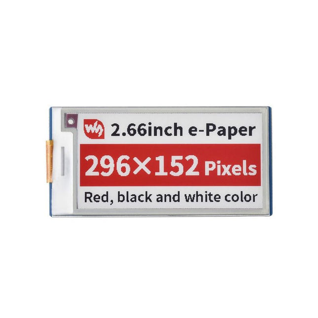
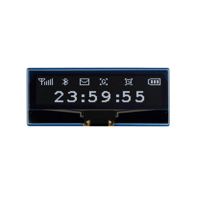
Features No backlight, keeps displaying last content for a long time even when power down Ultra low power consumption, basically power is only required for refreshing SPI interface, requires minimal IO pins Comes with development resources and manual (Raspberry Pi Pico C/C++ and MicroPython examples) Specifications Operating voltage 3.3 V Display color red, black, white Interface 3-wire SPI, 4-wire SPI Grey scale 2 Outline dimensions 74.00 × 37.5 0mm Full refresh time 15s Display size 60.088 × 30.704 mm Refresh power 42.4 mW (typ.) Dot pitch 0.203 × 0.202 mm Standby current <0.01 uA (almost none) Resolution 296×152 pixels Viewing angle >170° Downloads Wiki
This affordable and increasingly powerful FPGA board is a fantastic starting point into the world of FPGAs and the heart of your next project. Finally, now that SparkFun builds this board, we added a Qwiic connector for easy I²C integration!
The Alchitry Au features a Xilinx Artix 7 XC7A35T-1C FPGA with over 33,000 logic cells and 256 MB of DDR3 RAM. The Au offers 102 3.3 V logic level IO pins, 20 of which can be switched to 1.8 V; Nine differential analogue inputs; Eight general-purpose LEDs; a 100 MHz on-board clock that can be manipulated internally by the FPGA; a USB-C connector to configure and power the board; and a USB to serial interface for data transfer. To make getting started even easier, all Alchitry boards have full Lucid support, a built-in library of useful components to use in your project, and a debugger!
Features
Artix 7 XC7A35T-1C - 33,280 logic cells
256 MB DDR3 RAM
102 IO pins (3.3 V logic level, 20 of them can be switched to 1.8 V for LVDS)
Nine differential analogue inputs (One dedicated, Eight mixed with digital IO)
USB-C to configure and power the board
Eight general-purpose LEDs
One button (typically used as a reset)
100 MHz on-board clock (can be multiplied internally by the FPGA)
Powered with 5 V through USB-C port, 0.1" holes, or headers
USB to serial interface for data transfer (up to 12 Mbaud)
Qwiic Connector
Dimensions: 65 x 45 mm
Downloads
Datasheet
Schematic
3D Model (IGES File)
Element Eagle Library
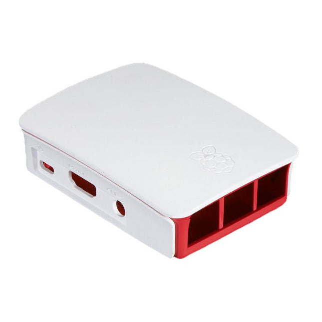
High-quality ABS construction Removable side panels and lid for easy access to GPIO, camera and display connectors Light pipes for power and activity LEDs Extraordinarily handsome Colour: white/red
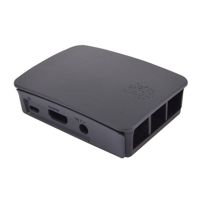
High-quality ABS construction Removable side panels and lid for easy access to GPIO, camera and display connectors Light pipes for power and activity LEDs Extraordinarily handsome Colour: black/grey
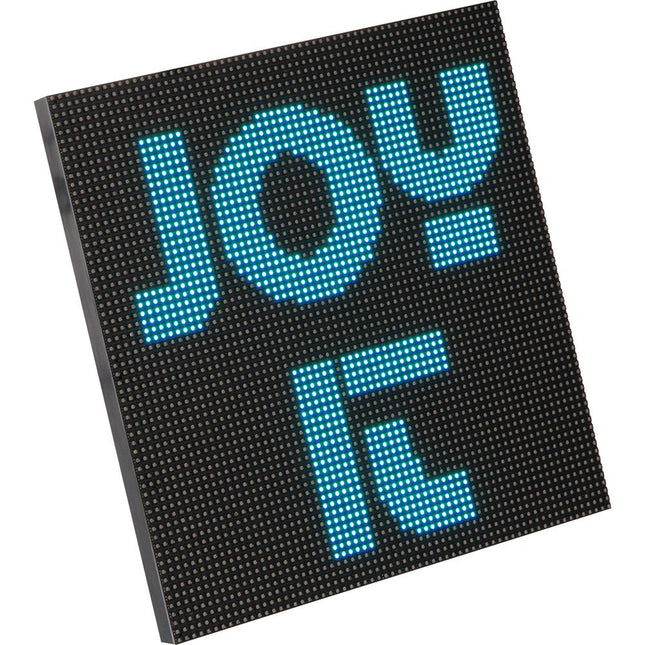
The RGB matrix module is equipped with 4096 LEDs and is characterized by a particularly small grid size of only 3mm. This makes it ideal for pictorial representations. Video sequences can also be displayed.
The module is supplied with the necessary cables. It is perfectly suited in combinations with single board computers like the Raspberry Pi, Arduino, BBC Microbit and many more.
Specifications
Display
RGB-LED
Resolution
64 x 64
Amount of LED
4096 LEDs
LED Size
3 mm Pitch
Supply Voltage
5 V
Max. Power Input
40 W
Control
1/32 Scan
Operating Temperature
-20~55°C
Viewing Angle
140°
Pixel Density
111111 Pixel/m²
Dimensions
192 x 192 x 14 mm
Weight
246 g
Items Shipped
LED-Matrix, Kabel
Downloads
Datasheet
Manual
As demand for solar panel installation has risen sharply, especially for installations larger than balcony power plants, the order books of solar companies are full. If you ask for a quote today, you may have to wait a while, if your request isn't simply postponed indefinitely. Another consequence of the solar boom is that some companies are charging very high prices for installations.
Yet there is an obvious and radical solution to the problem of excessive prices: Do it yourself, as the English say. The price of materials is currently affordable, and it's the ideal time for those who do the work themselves. They couldn't save more. Add to this the satisfaction of doing something useful, both economically and ecologically, and the pleasure of building yourself.
In this special issue, you'll find a wide selection of Elektor assemblies, from solar panel controllers to solar water heaters and solar panel orientation systems. The issue also contains practical information on solar panel installation and the technology behind them. Finally, there are a number of articles on the subject of balcony power plants, from how to install them to how to connect them to the Internet...
Contents
BASICS
Dimensioning Photovoltaic Panel ArraysAn introduction to photovoltaic energy and the commonest techniques,followed by simplified calculation models and setup guidelines.
Light Sensor TechnologyMeasuring daylight using LEDs.
Solar Power Made SimpleSolar charging with and without a controller.
Cable Cross-sections and Energy Losses in Solar SystemsKey considerations on the minimum values to respect for electricalcurrent in solar panel cabling.
Solar ModulesEverything you always wanted to know about solar panels...
Ideal Diode ControllerDiode Circuits with Low Power Dissipation.
TIPS
Tracking for Solar Modules
zBot Solar/Battery Power Supply
Solar Cell Array Charger with Regulator
Solar Cell Voltage Regulator
Solar-Powered Night Light
Alternative Solar Battery Charger
PROJECTS
Energy LoggerMeasuring and Recording Power Consumption.
Tiny Solar SupplySunlight In, 3.3 V Out.
A Do-It-Yourself DTURead Data from Small Inverters by μC.
Solar ChargerPortable energy for people on the move.
Solar Thermal Energy RegulatorMaximum power point tracking explored.
2-amp Maximum Power Tracking ChargerSolar Power To The Max.
Computer-driven HeliostatFollow the sun or the stars.
Garden LightingUsing solar cells.
Solar Panel Voltage Converter for IoT DevicesYes we CAN exploit indoor lighting.
Travel ChargerFree power in the mountains.
Solar Cell Battery Charger/MonitorWith protection against deep discharge.
Solar-powered Battery ChargerPIC12C671 avoids overcharging and deep charging.
Converters for Photovoltaic PanelsContributed by TME (Transfer MultisortElektronik).
Solar Charging RegulatorFor panels up to 53 watts.
Solar-Powered ChargerFor lead-acid batteries.
CAN Bus + Arduino for Solar PV Cell MonitoringDetect and locate serviceable panels in large arrays.
Balcony Power Plant 2.0The latest: solar panels, installation and inverters
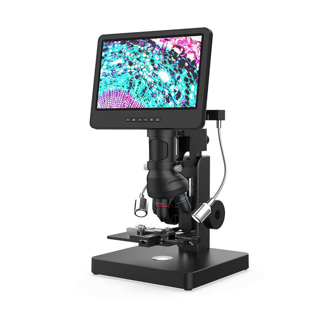
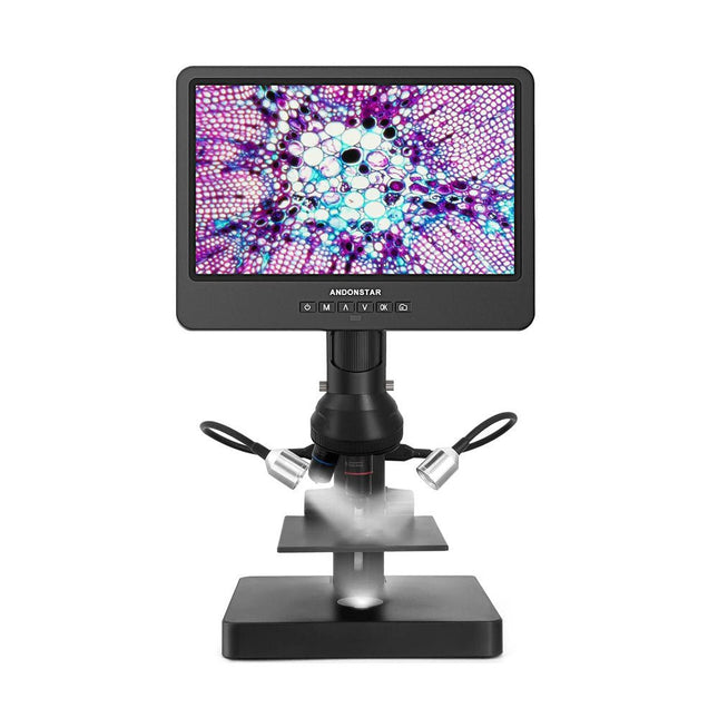
This versatile digital microscope covers a wide magnification range (18-720x, 1560-2040x, 2760-4080x, 3600-5100x, 60-240x) with 5 lenses for hobby, industrial and biologic purposes.
Lens A (18-720x) can be used to observe whole coins or parts, circuit boards, plants, stones, etc. With lens B (1560-2040x), C (2760-4080x) and M (3600-5100x) you can observe biological slides. Lens L is ideal for soldering and repair work.
In addition, the microscope has an endoscope for clear observation of the sides of components and inner tubes, allowing 360° viewing without blind spots.
Specifications
Magnification
Lens A
18-720x
Lens B
1560-2040x
Lens C
2760-4080x
Lens M
3600-5100x
Lens L
60-240x
Screen size
10 inch (25.7 cm)
Video resolution (max.)
UHD 2880x2160 (24fps)
Video format
MP4
Photo format
JPG
Photo resolution
5600x2400 (with interpolation)
Frame rate
Max. 120fps
HDMI output
Yes (only HDMI monitor displays)
PC output
Yes
Power supply
USB 5 V DC (not included)
Stand material
Metal
Stand size
20 x 19 x 40 cm
Included
1x Andonstar AD269S Digital Microscope
1x Metal stand with 2 LEDs
1x X-Y Moveable stage
1x Lens A
1x Lens set (B, C, M)
1x Lens L
1x Endoscope (+ accessories)
1x USB cable
1x HDMI cable
1x Remote control
1x Dimmer cable
3x Backdrop board
5x Biological slides
1x 32 GB microSD card
1x Observation box
1x Tweezers
1x Manual
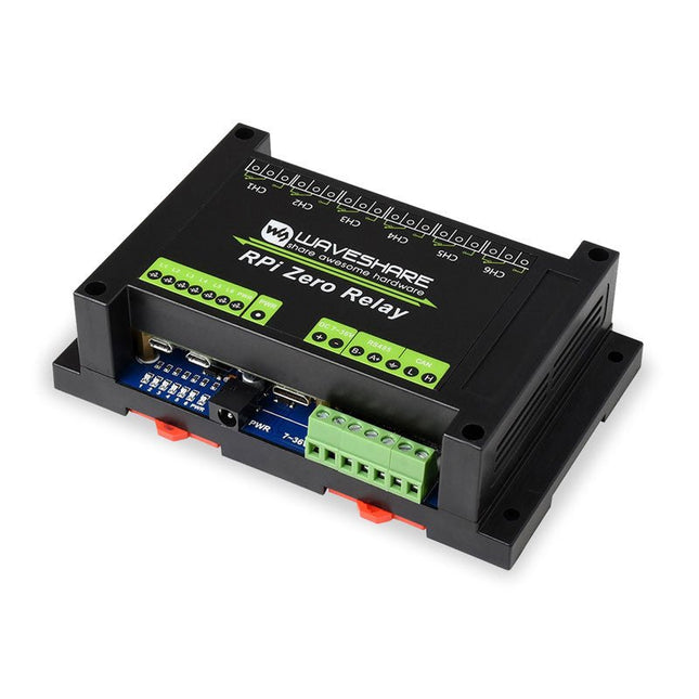
This Industrial 6-Channel Relay Module is suitable for Raspberry Pi Zero with pre-soldered pinheader. It provides RS485/CAN Bus, Power Supply Isolation, and Photocoupler Isolation.Features
RS485 half-duplex communication: using SP3485, UART control, auto RX/TX switch
CAN half-duplex communication: using MCP2515 + SN65HVD230 solution, SPI control
Onboard unibody power supply isolation, provides stable isolated voltage, needs no extra power supply for the isolated terminal
Onboard photocoupler isolation, prevent interference from external high-voltage circuit connected to the relay
Onboard TVS (Transient Voltage Suppressor), effectively suppress surge voltage and transient spike voltage in the circuit, lightningproof & anti-electrostatic
Onboard resettable fuses and protection diodes, ensuring current/voltage stable output, preventing over current/voltage, better shock-resistance performance
High quality relay, contact rating: ≤10A 250V AC or ≤10A 30V DC
ABS protection enclosure with rail-mount support, easy to install, safe to use
Comes with development resources and manual (wiringPi and python examples)
Specifications
Operating voltage: 7~36 V (industrial input voltage compatible)
Relay channel: 6ch
Communication Protocol: RS485, CAN
Contact form: 1NO 1NC
Included
1x ABS protection enclosure (top and bottom)
1x RPi Zero Relay
1x Screwdriver
1x OPTIONS 12 V, 1 A power adapter
1x Screws pack
DownloadsDocumentation
The SEQURE T55 Smart Mini Temperature Adjustable Soldering Hot Plate is a compact and efficient tool designed for precise preheating and desoldering tasks. With its adjustable temperature range from 50°C to 280°C (122°F to 536°F), it is suitable for various applications, e.g. cell phone repair, PCB assembly, etc.
Features
Adjustable heating temperature range: 50°C to 280°C (122°F to 536°F)
Equipped with a heat-resistant ceramic temperature sensor, ensuring high-accuracy data measurement under continuous high temperatures.
Automatically stops heating after reaching the preset working time.
Supports PD, QC, and DC (max 25 V).
Intelligent temperature control algorithm for temperature compensation and power adjustment.
128 x 32 resolution OLED display with a built-in buzzer to indicate operating status.
°C/°F conversion
Specifications
Heating Area
55 x 55 mm
Working Temperature
50-280°C (122-536°F)
Max Voltage
25 V
Max Power
95 W
Recommend Voltage
19-25 V
PD Power Supply
PD 20 V ≥3A
Power Supply Modes
PD, QC, DC
Interface
USB-C
Display
128 x 32 OLED
Menu Languages
English, Russian, and Chinese
Dimensions
55 x 60 x 37 mm
Weight
92 g
Included
1x SEQURE T55 Smart Mini Soldering Hot Plate
1x PD 65 W Power Supply (EU)
1x Fast Charging Cable (100 W/5 A)
The RP2040 contains two ARM Cortex-M0+ processors (up to 133 MHz) and features:
264 kB of embedded SRAM in six banks
6 dedicated IO for SPI Flash (supporting XIP)
30 multifunction GPIO:
Dedicated hardware for commonly used peripherals
Programmable IO for extended peripheral support
Four 12-bit ADC channels with internal temperature sensor (up to 0.5 MSa/s)
USB 1.1 Host/Device functionality
The RP2040 is supported with C/C++ and MicroPython cross-platform development environments, including easy access to runtime debugging. It has a UF2 boot and floating-point routines baked into the chip. While the chip has a large internal RAM, the board includes an additional 16 MB of external QSPI flash memory to store program code.
Features
Raspberry Pi Foundation's RP2040 microcontroller
16MB QSPI Flash Memory
JTAG PTH Pins
Thing Plus (or Feather) Form-Factor:
18x Multifunctional GPIO Pins
Four available 12-bit ADC channels with an internal temperature sensor (500 kSa/s)
Up to eight 2-channel PWM
Up to two UARTs
Up to two I²C buses
Up to two SPI buses
USB-C Connector:
USB 1.1 Host/Device functionality
2-pin JST Connector for a LiPo Battery (not included):
500 mA charging circuit
Qwiic Connector
Buttons:
Boot
Reset
LEDs:
PWR - Red 3.3 V power indicator
CHG - Yellow battery charging indicator
25 - Blue status/test LED (GPIO 25)
WS2812 - Addressable RGB LED (GPIO 08)
Four Mounting Holes:
4-40 screw compatible
Dimensions: 2.3' x 0.9'
RP2040 Features
Dual Cortex M0+ processors, up to 133 MHz
264 kB of embedded SRAM in 6 banks
6 dedicated IO for QSPI flash, supporting execute in place (XIP)
30 programmable IO for extended peripheral support
SWD interface
Timer with 4 alarms
Real-time counter (RTC)
USB 1.1 Host/Device functionality
Supported programming languages
MicroPython
C/C++
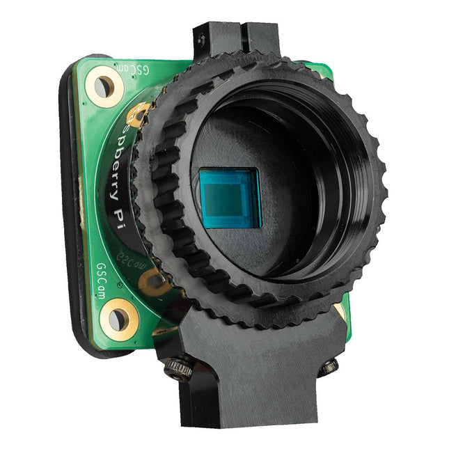
The Raspberry Pi Global Shutter Camera is a specialised 1.6 MP camera from Raspberry Pi that is able to capture rapid motion without introducing artefacts typical of rolling shutter cameras. It is ideally suited to fast motion photography and to machine vision applications, where even small amounts of distortion can seriously degrade inference performance.
With a large pixel size of 3.45 x 3.45 μm providing high light sensitivity, the Global Shutter Camera can operate with short exposure times (as low as 30 μs with adequate lighting), an advantage for high-speed photography.
It features a 1.6 MP Sony IMX296 sensor, and it has the same C/CS-mount lens assembly as the Raspberry Pi High Quality Camera, for compatibility with the same broad variety of lenses. In common with other global shutter sensors, the IMX296 has a lower resolution than similarly sized rolling shutter sensors; a low pixel count is appropriate for machine vision applications, where high-resolution images are challenging to process in real time. The Global Shutter Camera's lower resolution means that with appropriate lens magnification, an image suitable for processing by a machine vision model can be captured natively.
The Raspberry Pi Global Shutter Camera is compatible with any Raspberry Pi computer that has a CSI connector.
Specifications
Form factor
38 x 38 x 19.8 mm (29.5 mm adapter and dust cap)
Weight
34 g (41 g with adapter and dust cap)
Sensor
Sony IMX296LQR-C
Resolution
1.58 MP (color)
Sensor size
6.3 mm (sensor diagonal)
Pixel size
3.45 x 3.45 μm
Output
RAW10
Back focus length of lens
Adjustable (12.5-22.4 mm)
Lens standards
CS-MountC-Mount (C-CS adapter included)
IR cut filter
Integrated
Ribbon cable length
150 mm
Included accessories
C-CS mount adapterScrewdriver
Tripod mount
1/4”-20
Included
Raspberry Pi Global Shutter Camera
C-CS mount adapter
Screwdriver
Ribbon cable (150 mm)
Downloads
Datasheet
The FNIRSI DSO153 is a highly practical and cost-effective handheld oscilloscope with a real-time sampling rate of 5 MSa/s, 1 MHz bandwidth, and complete triggering function (single, normal, auto). It can be used freely for both periodic analog signals and non-periodic digital signals, and can measure up to ±400 V voltage with an efficient one-click AUTO, which can display the measured waveform without complicated adjustments. Additionally, it features a function signal generator capable of outputting 14 types of signals (10 KHz).
Equipped with a 2.8-inch 320x240 resolution HD LCD screen and a built-in 1000 mAh high-quality lithium battery, it can be used for about 4 hours when fully charged.
Features
2.8-inch HD LCD display with 320x240 Resolution
Portable Pocket Oscilloscope with Signal Generator
Lightweight, mini-sized, assembled
Faster sampling: 5 MS/s, 1 MHz bandwidth
Versatile triggering: Single, Normal, Auto
User-friendly: One-button setup
Extended battery: 1000 mAh, 4 hours
Multi-functionality: 10 KHz Sine Wave Generator
Specifications
Bandwidth
1 MHz
Sampling rate
5 MSa/s
Vertical Sensitivity
10mV/Div – 20V/Div
Time Base Range
500ns/Div – 20s/Div
Voltage Range
X1: ±40 V (Vpp: 80 V)X10: ±400 V (Vpp: 800 V)
Trigger Method
Auto / Normal / Single
Coupling Method
AC/DC
Frequency Range
0-10 KHz
Duty Cycle Range
0-100%
Amplitude Range
0.1-3.3 V
Display
2.8 inches (Resolution: 320 x 240)
USB Charging
5 V/1 A
Lithium Battery Capacity
1000 mAh
Dimensions
99 x 68.3 x 19.5 mm
Weight
100 g
Included
1x FNIRSI DSO153 Oscilloscope
1x P6100 oscilloscope probe
1x Adapter
1x Alligator clip probe
1x USB charging cable
1x Lanyard
1x Manual
Downloads
Manual
Firmware V1.1.8
A Practical Guide to AI, Python, and Hardware Projects
Welcome to your BeagleY-AI journey! This compact, powerful, and affordable single-board computer is perfect for developers and hobbyists. With its dedicated 4 TOPS AI co-processor and a 1.4 GHz Quad-core Cortex-A53 CPU, the BeagleY-AI is equipped to handle both AI applications and real-time I/O tasks. Powered by the Texas Instruments AM67A processor, it offers DSPs, a 3D graphics unit, and video accelerators.
Inside this handbook, you‘ll find over 50 hands-on projects that cover a wide range of topics—from basic circuits with LEDs and sensors to an AI-driven project. Each project is written in Python 3 and includes detailed explanations and full program listings to guide you. Whether you‘re a beginner or more advanced, you can follow these projects as they are or modify them to fit your own creative ideas.
Here’s a glimpse of some exciting projects included in this handbook:
Morse Code Exerciser with LED or BuzzerType a message and watch it come to life as an LED or buzzer translates your text into Morse code.
Ultrasonic Distance MeasurementUse an ultrasonic sensor to measure distances and display the result in real time.
Environmental Data Display & VisualizationCollect temperature, pressure, and humidity readings from the BME280 sensor, and display or plot them on a graphical interface.
SPI – Voltmeter with ADCLearn how to measure voltage using an external ADC and display the results on your BeagleY-AI.
GPS Coordinates DisplayTrack your location with a GPS module and view geographic coordinates on your screen.
BeagleY-AI and Raspberry Pi 4 CommunicationDiscover how to make your BeagleY-AI and Raspberry Pi communicate over a serial link and exchange data.
AI-Driven Object Detection with TensorFlow LiteSet up and run an object detection model using TensorFlow Lite on the BeagleY-AI platform, with complete hardware and software details provided.
17 Sensor Modules & 21 Tutorials
The Elecrow All-in-One Starter Kit for Raspberry Pi Pico 2 is an ideal choice for beginners embarking on their learning journey with the RP2040-based Pico 2. This comprehensive kit integrates 17 different sensors onto a single board and features a 2.4-inch full-color TFT touch screen. No soldering or wiring is required – it's ready to use right out of the box, enabling a quick and seamless start.
The kit includes more than 20 creative tutorials, ranging from basic to advanced levels. These step-by-step guides help users gradually become familiar with various sensors, develop logical thinking skills, and spark creativity. Its compact, portable suitcase design makes it easy to carry and perfect for learning on the go.
To enhance the learning experience, the kit also features 20 programmable full-color ambient lights and built-in mini-games, allowing for an engaging blend of education and entertainment.
Features
Powered by Raspberry Pi Pico 2 (RP2350 chip)
Includes 17 integrated sensors with various functions, along with over 20 creative tutorials
All-in-one sensor board design – no soldering required, ready to use out of the box, perfect for quick prototyping
Compact and stylish portable suitcase – small, elegant, and easy to carry
2.4-inch full-color TFT touchscreen
20 programmable full-color ambient lights for dynamic visual effects
Built-in mini-games – play instantly after boot-up, enabling a smooth transition between learning and fun
Sensores
1x Temperature & Humidity Sensor
4x Buttons
1x Ultrasonic Ranging Sensor
1x Light Sensor
1x Linear Potentiometer
3x LEDs
1x Buzzer
1x 2.4-inch TFT Display
1x Infrared Remote
1x Relay
1x Servo motor
1x Sound Sensor
1x Accelerometer & Gyro
1x Touch Sensor
1x Vibration Motor
1x Hall Sensor
1x Gas Sensor (MQ2)
Specifications
All-in-one Starter Kit for Raspberry Pi Pico 2
All-in-one Starter Kit for Arduino
Main Processor
Raspberry Pi Pico 2 RP2350
ATmega328P
Number of Sensors
17 sensors
15 sensors (including 1 Humidity sensor)
Sensor Board Design
Integrated sensor board, no soldering or complex wiring required
Display
2.4-inch TFT full-color touch screen
N/A
Ambient Lights
20 full-color ambient lights, switchable via touch screen
N/A
Built-in Mini Games
Yes
No
Expansion Interfaces
N/A
6 Crowtail interfaces(3x I/O, 2x I²C, 1x UART)
Programming Environment
Based on Arduino software
Number of Tutorials
21 creative tutorials
Interface
USB-C
Dimensions
195 x 170 x 46 mm
Weight
380 g
340 g
Included
1x Elecrow All-in-One Starter Kit for Raspberry Pi Pico 2
1x IR Remote control
1x USB-C cable
Downloads
Datasheet
Manual
Wiki
This versatile digital microscope covers a wide magnification range (18-720x, 1560-2040x, 2760-4080x) with 3 lenses for hobby, industrial and biologic purposes. Lens A (18-720x) can be used to observe whole coins or parts, circuit boards, plants, stones, etc. With lens B (1560-2040x) and C (2760-4080x) you can observe biological slides.
Specifications
Magnification
Lens A
18-720
Focus range
12-320 mm
Lens B
1560-2040
Focus range
7-8 mm
Lens C
2760-4080
Focus range
3-4 mm
Screen size
10 inch (25.7 cm)
Video resolution (max.)
UHD 2880x2160 (24fps)
Video format
MP4
Photo format
JPG
Photo resolution
5600x2400 (with interpolation)
Frame rate
Max. 120fps
HDMI output
Yes (only HDMI monitor displays)
PC output
Yes
Power supply
USB 5 V DC (not included)
Stand material
Pro Plastic
Stand size
20 x 19 x 30 cm
Included
1x Andonstar AD249S-P Digital Microscope
1x Pro plastic stand
1x Lens A (fixed)
1x Lens (B & C)
1x USB cable
1x HDMI cable
1x Remote control
1x Dimmer cable
3x Backdrop board
1x Slides kit
1x 32 GB microSD card
1x Observation box
1x Tweezers
1x Screw driver
1x User manual
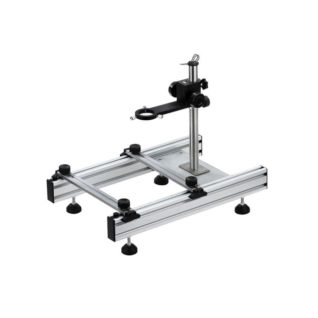
This multi-purpose tool offers an excellent all round solution, ideal for holding big size PCBs and desoldering work, etc.
Features
The arms of the repair station can move up and down conveniently, easy for operation.
The adjustable parts are made of the same material for microscope, with high quality, perfect stability and precision.
The rubber feet can move in all directions, ensuring the operation platform is always on a flat surface.
Suitable for desoldering BGA ICs.
Specifications
Rough adjusting range in height
0∼230 mm
Precise adjusting range in height
0∼60 mm
Max. holding size of PCB
250 mm (length or width)
Min. holding size of PCB
20 mm (length or width)
Specifications Lens diameter: 90 mm / 3.54' Dioptre: lens Ø 90 mm: dioptre 3 – magnification: 1.75 Power supply: 3 x 1.5 V AAA battery Dimensions: 210 x 170 x 110 mm / 8.3 x 6.7 x 4.3' Weight: 615 g Material: Stand: stainless steel Lens: glass Connecting parts: copper
Features Adopts both 4-wire SPI and I²C interface, better compatibility, fast data rate Standard Raspberry Pi Pico header, supports Raspberry Pi Pico series boards Comes with development resources and manual (Raspberry Pi Pico C/C++ and MicroPython examples) Specifications Logical voltage 3.3 V Viewing angle >160° Operating voltage 3.3 V/5 V Resolution 128×32 pixels Communication interface 4-wire SPI, I²C Display size 55.02 × 13.10 mm Display panel OLED Pixel size 0.41 × 0.39 mm Driver SSD1305 Dimensions 63.00 × 26.00 mm
The RedBoard Artemis has the improved power conditioning and USB to serial that we've refined over the years on our RedBoard line of products. A modern USB-C connector makes programming easy. A Qwiic connector makes I²C easy. The RedBoard Artemis is fully compatible with SparkFun's Arduino core and can be programmed easily under the Arduino IDE. We've exposed the JTAG connector for more advanced users who prefer to use professional tools' power and speed. We've added a digital MEMS microphone for folks wanting to experiment with always-on voice commands with TensorFlow and machine learning. We've even added a convenient jumper to measure current consumption for low power testing. With 1MB flash and 384k RAM, you'll have plenty of room for your sketches. The on-board Artemis module runs at 48MHz with a 96MHz turbo mode available and with Bluetooth to boot! Features Arduino Uno R3 Footprint 1M Flash / 384k RAM 48MHz / 96MHz turbo available 24 GPIO - all interrupt capable 21 PWM channels Built-in BLE radio 10 ADC channels with 14-bit precision 2 UARTs 6 I²C buses 4 SPI buses PDM Interface I²S Interface Qwiic Connector