CrowBot BOLT is an ESP32-controlled, intelligent, simple and easy-to-use open source robot car. It is compatible with the Arduino and MicroPython environments, with graphical programming via Letscode. 16 learning courses with interesting experiments are available.
Features
16 lessons in three languages (Letscode, Arduino, Micropython), fast learning and fun experiments
Compatible with Arduino, MicroPython development environment, using Letscode graphical programming, easy to use
Strong scalability, with a variety of interfaces, can be expanded and used with Crowtail modules
A variety of remote control modes, you can use the infrared remote control and joystick to control the car
Specifications
Processor
ESP32-Wrover-B (8 MB)
Programming
Letscode, Arduino, Micropython
Control method
Bluetooth Remote Control/Infrared Remote Control
Input
Button, Light sensor, Infrared Receiving Module, Ultrasonic Sensor, Line Tracking Sensor
Output
Buzzer, Programmable RGB Light, Motor
Wifi & Bluetooth
Yes
Light sensor
Can realize the function of chasing light or avoiding light
Ultrasonic Sensor
When an obstacle is detected, the driving route of the car can be corrected to avoid the obstacle
Line Tracking Sensor
Can make the car move along the dark/black lines, intelligently judge and correct the driving path
Buzzer
Can make the car sound/whistle, bringing a more direct sensory experience
Programmable RGB Light
Through programming, it can show colorful lights in different scenes
Infrared receiver
Receive infrared remote control signals to realize remote control
Interfaces
1x USB-C, 1x I²C, 1x A/D
Motor type
GA12-N20 Micro DC Gear Motor
Operating temperature
-10℃~+55℃
Power supply
4x 1.5 V batteries (not included)
Battery life
1.5 hours
Dimensions
128 x 92 x 64 mm
Weight
900 g
Included
1x Chassis
1x Ultrasonic Sensor
1x Battery Holder
2x Wheels
4x M3x8 mm Screws
2x M3x5 mm Copper Column
2x Side Acrylic Plates
1x Front Acrylic Plates
1x Screwdriver
2x 4 Pin Crowtail Cable
1x USB-C Cable
1x Infrared remote control
1x Instructions & Line Track Map
1x Joystick
Downloads
Wiki
CrowBot-BOLT_Assembly-Instruction
Joystick-for-CrowBot-BOLT_Assembly-Instruction
CrowBot_BOLT_Beginner’s_Guide
Designing Documents of CrowBot
Designing Documents of Joystick
Lesson Code
3D Model
Factory Source Code
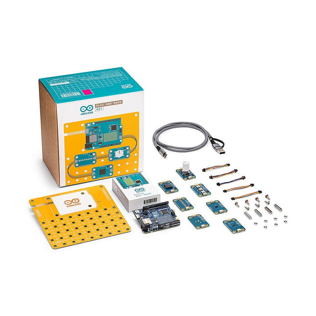
Build your first IoT devices with this kit by seamlessly integrating hardware and software without diving into complex theory.
Plug and Make Kit is the easiest way to get started with Arduino. It includes everything you need for your very first seven projects – as well as many more that our community shares and you can invent yourself!
Weather Report: Never get caught in the rain again, with a visual reminder to take an umbrella when needed
Hourglass: Who needs an egg timer? Customize your own digital hourglass
Eco Watch: Make sure your plants thrive in the perfect temperature and humidity
Game Controller: Level up with your very own HID (Human Interface Device) gamepad
Sonic Synth: Get one step closer to being a rockstar, DJ or sound engineer!
Smart Lights: Set the mood with your very own smart lamp
Touchless Lamp: Control lights with a simple gesture
Each idea is inspiration for a fun activity that will not only teach you the basics of do-it-yourself electronics but leave you with a great sense of accomplishment. You can make technology too!
With the innovative Modulino nodes, simply connect them sequentially using the onboard Qwiic connector of the Arduino Uno R4 WiFi. By utilizing one of the Arduino Cloud templates, you can swiftly transform your concept into a fully operational project.
Features
No extra tools needed, all you have to kick off you journey as maker is included in the kit.
No breadboard and no soldering are involved.
Build a fully functional IoT project, understanding its inner working, in under 45 minutes.
Start from the project you find more interesting, you define your own learning path.
Continue learning and working on your projects from any connected computer using the online Arduino ecosystem.
Modulino
Modulino are sensors and actuators that simply connect via the Uno R4 WiFi’s onboard Qwiic connector. You can connect more than one for more complex projects and never have to wonder which side goes where, because the connector is polarized.
Modulino Knob: for super-fine value adjustments
Modulino Pixels: eight LEDs to shine bright, dim down, or change color
Modulino Distance: a time-of-flight proximity sensor to measure distances with precision
Modulino Movement: to perfectly capture movements like pitch, roll or tilt
Modulino Buzzer: to generate your own alarm sounds or simple tunes
Modulino Thermo: a sensor for both temperature and humidity data
Modulino Buttons: three buttons for quick project navigation
Specifications
Board included
Arduino Uno R4 WiFi
Modulino nodes
Communications
I²C (over Qwiic connector)
Operational voltage
3.3 V
Modulino nodes included
Modulino Movement
LSM6DSOXTR
0x6A (0x6B)
Modulino Distance
VL53L4CDV0DH/1
0x29
Modulino Thermo
HS3003
0x44
Modulino Knob
PEC11J (STM32C011F4 for I²C communication)
0x76 (address can change via software)
Modulino Buzzer
PKLCS1212E4001-R1 (STM32C011F4 for I²C communication)
0x3C (address can change via software)
Modulino Pixels
8 LC8822-2020 (STM32C011F4 for I²C communication)
0x6C (address can change via software)
Modulino Buttons
3 push buttons plus 3 yellow LEDs (STM32C011F4 for I²C communication)
0x7C (address can change via software)
Included
1x Arduino Uno R4 WiFi
1x Modulino base
7x Modulino sensors
1x USB-C cable
7x Qwiic cables
24x Screws M3 (10 mm)
20x Nuts M3
4x Metal spacers
Downloads
Datasheet
Schematics
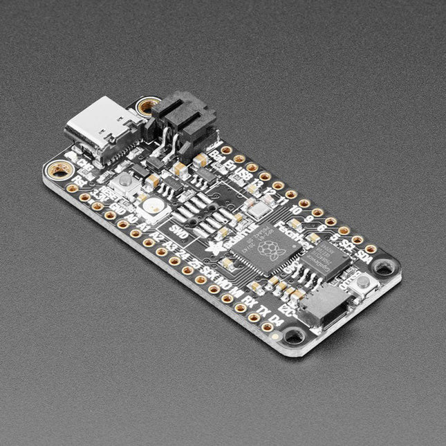
Inside the RP2040 is a 'permanent ROM' USB UF2 bootloader. What that means is when you want to program new firmware, you can hold down the BOOTSEL button while plugging it into USB (or pulling down the RUN/Reset pin to ground) and it will appear as a USB disk drive you can drag the firmware onto. Folks who have been using Adafruit products will find this very familiar – Adafruit uses the technique on all thier native-USB boards. Just note you don't double-click reset, instead hold down BOOTSEL during boot to enter the bootloader!The RP2040 is a powerful chip, which has the clock speed of our M4 (SAMD51), and two cores that are equivalent to our M0 (SAMD21). Since it is an M0 chip, it does not have a floating point unit, or DSP hardware support – so if you're doing something with heavy floating-point math, it will be done in software and thus not as fast as an M4. For many other computational tasks, you'll get close-to-M4 speeds!For peripherals, there are two I²C controllers, two SPI controllers, and two UARTs that are multiplexed across the GPIO – check the pinout for what pins can be set to which. There are 16 PWM channels, each pin has a channel it can be set to (ditto on the pinout).Technical Specifications
Measures 2.0 x 0.9 x 0.28' (50.8 x 22.8 x 7 mm) without headers soldered in
Light as a (large?) feather – 5 grams
RP2040 32-bit Cortex M0+ dual core running at ~125 MHz @ 3.3 V logic and power
264 KB RAM
8 MB SPI FLASH chip for storing files and CircuitPython/MicroPython code storage. No EEPROM
Tons of GPIO! 21 x GPIO pins with following capabilities:
Four 12 bit ADCs (one more than Pico)
Two I²C, Two SPI and two UART peripherals, one is labeled for the 'main' interface in standard Feather locations
16 x PWM outputs - for servos, LEDs, etc
The 8 digital 'non-ADC/non-peripheral' GPIO are consecutive for maximum PIO compatibility
Built in 200 mA+ lipoly charger with charging status indicator LED
Pin #13 red LED for general purpose blinking
RGB NeoPixel for full color indication.
On-board STEMMA QT connector that lets you quickly connect any Qwiic, STEMMA QT or Grove I²C devices with no soldering!
Both Reset button and Bootloader select button for quick restarts (no unplugging-replugging to relaunch code)
3.3 V Power/enable pin
Optional SWD debug port can be soldered in for debug access
4 mounting holes
24 MHz crystal for perfect timing.
3.3 V regulator with 500mA peak current output
USB Type C connector lets you access built-in ROM USB bootloader and serial port debugging
RP2040 Chip Features
Dual ARM Cortex-M0+ @ 133 MHz
264 kB on-chip SRAM in six independent banks
Support for up to 16 MB of off-chip Flash memory via dedicated QSPI bus
DMA controller
Fully-connected AHB crossbar
Interpolator and integer divider peripherals
On-chip programmable LDO to generate core voltage
2 on-chip PLLs to generate USB and core clocks
30 GPIO pins, 4 of which can be used as analog inputs
Peripherals
2 UARTs
2 SPI controllers
2 I²C controllers
16 PWM channels
USB 1.1 controller and PHY, with host and device support
8 PIO state machines
Comes fully assembled and tested, with the UF2 USB bootloader. Adafruit also tosses in some header, so you can solder it in and plug it into a solderless breadboard.
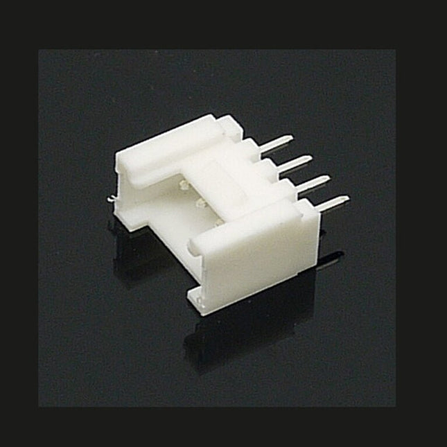
The universal 4 Pin connector is a white 4-pin buckled connector used on Stem, Twigs and Grove cables. The pin spacing is 2 mm. There are 10 connectors per bag. They can be used in DIY projects.
The JYE Tech WAVE2 is a 2-channel oscilloscope designed for hobbyists, educational institutions, and professionals in electronics and mechatronics.
Features
No. of Channels: 2
Bandwidth: 0-200 KHz per channel
Sensitivity range: 5 mV/DIV – 20 V/DIV (using x1 probe)
Maximum input voltage: 50 Vpk (using x1 probe)
Maximum real time sampling rate: 1 MS/s
Time Base range 10 us/DIV – 500 s/DIV
X-Y Display Feature: Yes
Function Generator Capability: Built-in 0-20 KHz (sine) dual channel DDS function generator
Display Resolution: 320 x 240 Color display
Display Size: 2.4″
Touch Display Capability: Yes
Battery powered and portable (battery not included in DIY Kit)
Specifications
General
2.4” 320x240 color display
Touch panel operation
Y-X mode available
Built-in 2-channel DDS function generator
Light weight and portable
Vertical
Number of Channel: 2
Analog Bandwidth: DC – 200 KHz
Sensitivity: 5 mV/Div - 20 V/Div (with x1 probe)
Sensitivity error: <5%
Resolution: 12-bit
Input Impedance: 1 M ohm / 25 pF
Maximum Input Voltage: 50 Vpk
Coupling: DC, AC
Horizontal
Max Real-time Sampling Rate: 1 Msps (per channel)
Timebase: 10 us/Div - 500 s/Div
Record Length: 1024 points
Trigger
Trigger Modes: Auto, Normal, Single
Trigger Types: Rising/falling edge
Trigger Position: 1/2 of buffer size
Trigger Source: Ch1, Ch2, External
Maximum external trigger voltage: 15 V
External trigger threshold: LVTTL
Function Generator
Number of channel: 2
Waveform type: Sine, Square, Saw-tooth, Stair
Frequency range: DC – 20 KHz (Sine)
Amplitude range: 0 – 3 V (peak value)
Offset: 0 V or +3.3 V
Duty Cycle: 0 – 100%
Phase: -360 – 360 degree
Power Supply
Powered on 3.7 V Li-ion battery or USB
Current consumption: ~30 0mA @ 3.7 – 5V
Internal batter charger (optional)
Automatic power off on battery
Battery running time: Appr. 3 hrs (when fully charged)
Other Features
Y-X display mode
On-screen measurement display
Save / recall up to 4 captures
Serial output of captured data
Serial port format: LVTTL, 115200 bps, 8N1
Built-in 1 KHz/3.3 V test signal
Physical
Dimensions: 115 x 72 x 30 mm
Weight: 0.29 kg (excluding battery and probes)
The JOY-iT JDS2915 is a powerful 2-channel signal generator capable of producing frequencies up to 15 MHz. It offers a wide range of waveforms to cater to diverse re quirements. With its compact de sign, it's perfect for on-the-go applications, and the ability to power it via a power bank ensures you're not confined to a single location.
Additionally, the device comes with an integrated 1-channel frequency counter, enhancing the precision and versatility of your measure ments and experiments.
Specifications
Channels
2-channel Signal generator1-channel Frequency meter
Frequency Range
Sine: 0-15 MHzSquare, triangle: 0-15 MHzTTL, pulse: 0-6 MHz
Signal Forms
Sine, square, triangle, pulse, half / solid wave, exponential rise/ fall
Measuring Range Frequency Counter
1 MHz - 100 MHz
Frequency Accuracy
± 20 ppm
Frequency Stability
± 1 Ppm/3h
Sampling Rate
266 MSa/s
Display
2.4" TFT color LCD
Vertical Shaft Resolution
14 bits
Amplitude Range
<10 MHz : 0-20 Vpp>10 MHz : 0-10 Vpp
Amplitude Resolution
1 mV
Amplitude Stability
± 5%/5h
Amplitude Flatness
<10 MHz: ±5%>10 MHz: ±10%
Impedance of Output
50 Ω ±10%
Dimensions
145 x 95 x 55 mm
Weight
680 g
Included
1x JOY-iT JDS2915 Signal Generator
1x Power supply unit
2x BNC crocodile clip cables
Downloads
Datasheet
Manual
Software
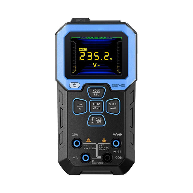
The FNIRSI DMT-99 is an intelligent digital multimeter with 10000 counts, which offers a high measuring range and high resolution. It can accurately measure AC/DC voltage, AC/DC current, 10 A current and can also be used to test conductivity, capacitance, frequency, duty cycle, resistance, diode, temperature, NCV, live wire detection, etc.
It is suitable for various electronic maintenance fields such as mechanical engineering, laboratories, automobiles and home appliances. It is equipped with a 1500 mAh lithium battery and a 2.4' TFT full-color display with a resolution of 240 x 320 pixels.
Specifications
Function
Range
Accuracy
DC voltage
9.999 V/99.99 V/999.9 V
±(0.5%+3)
AC voltage
9.999 V/99.99 V/750.0 V
±(1%+3)
DC current
9999 uA/99.99 mA/999.9 mA/9.999 A
±(1.2%+3)
AC current
9999 uA/99.99 mA/999.9 mA/9.999 A
±(1.5%+3)
Resistance
9.999 MΩ/999.9 KΩ/99.99 KΩ/9.999 KΩ/999.9 Ω
±(1.5%+3)
99.99 MΩ
±(1.5%+3)
Capacitance
999.9 µF/99.99 µF/9.999 µF/999.9 nF/99.99 nF/9.999 nF
±(2.0%+3)
9.999 mF/99.99 mF
±(5.0%+3)
Frequency
9.999 MHz/999.9 KHz/9999 KHz/9.999 KHz/999.99 Hz/99.99 Hz/9.999 Hz
±(0.1%+3)
Temperature
-55~1300°C (-64~2372°F)
±(2.5%+3)
Diode
Yes
Continuity test
Yes
NVC
Yes
Live wire detection
Yes
Max counts
10000 counts
Battery capacity
1500 mAh
Dimensions
155 x 80 x 36 mm
Weight
191 g
Included
1x FNIRSI DMT-99 Multimeter
2x Test pens
1x USB-C charging cable
1x Manual
Downloads
Manual
Firmware V2.4
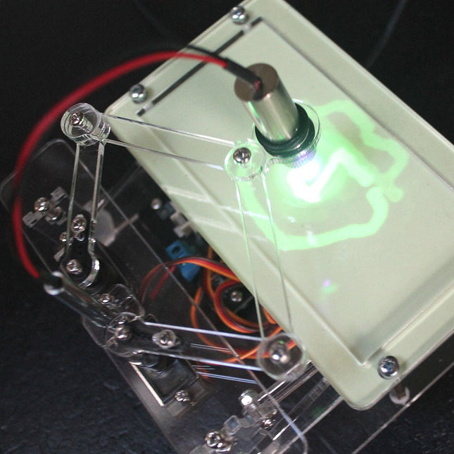
The Elektor Laser Head transforms the Elektor Sand Clock into a clock that writes the time on glow-in-the-dark film instead of sand. In addition to displaying the time, it can also be used to create ephemeral drawings. The 5 mW laser pointer, with a wavelength of 405 nm, produces bright green drawings on the glow-in-the-dark film. For best results, use the kit in a dimly lit room. Warning: Never look directly into the laser beam!
The kit includes all the necessary components, but soldering three wires is required.
Note: This kit is also compatible with the original Arduino-based Sand Clock from 2017. For more details, see Elektor Magazine 1-2/2017 and Elektor Magazine 1-2/2018.
With the M.2 MicroMod connector, connecting your ESP32 Processor is a breeze. Match up the key on your processor's bevelled edge connector to the key on the M.2 connector and secure it with a screw (included with all Carrier Boards). If you need to swap out your processor for a strong wireless option, make sure to check out the MicroMod ESP32! The ESP32 includes a laundry list of functionality, including the dual-core Tensilica LX6 microprocessor, 240MHz clock frequency, 520kB internal SRAM, integrated WiFi transceiver, integrated dual-mode Bluetooth, and hardware-accelerated encryption (AES, SHA2, ECC, RSA-4096). With this MicroMod processor board, you have access to 8 general use IO pins, dedicated analogue, digital, and PWM pins, as well as all the fan favourites - SPI, I²C, UART, and SDIO. Add to that 16MB flash storage and sleep current of around 500µA, and you've got a perfect storm of versatility. Features Dual-core Tensilica LX6 microprocessor Up to 240 MHz clock frequency 520 kB internal SRAM 128 mbit / 16 MB flash storage Integrated 802.11 BGN WiFi transceiver Integrated dual-mode Bluetooth (classic and BLE) 2.7-3.6 V operating range 500µA sleep current under hibernation 10-electrode capacitive touch support Hardware-accelerated encryption (AES, SHA2, ECC, RSA-4096) 1x USB dedicated for programming and debugging 1x UART 2x I²C 1x SPI 7x GPIO 2x Digital Pins 2x Analog Pins 2x PWM Status LED VIN Level ADC
The HDS242 is a portable 2-in-1 multifunctional tester, which can be used as a 2-ch oscilloscope and multimeter. It features a high-contrast 3.5-inch color display suitable for outdoor facility maintenance, rapid on-site measurement, automobile maintenance, power detection. etc.
Features
Oscilloscope + Multimeter
3.5-inch high-resolution, high-contrast color LCD display – suitable for outdoor use
18650 lithium battery – can work continuously for up to 6 hours
USB Type-C interface – support power bank and PC connection
Self-calibration function
SCPI supported – facilitate secondary development
Specifications
Oscilloscope
Bandwidth
40 MHz
Channels
2-ch Oscilloscope
Sample Rate
250 MSa/s
Acquisition Model
Normal, Peak detect
Record Length
8K
Display
3.5-inch LCD
Waveform Refresh Rate
10,000 wfrms/s
Input Coupling
DC, AC, and Ground
Input Impedance
1 MΩ ±2%, in parallel with 16pF ±10pF
Probe Attenuation Factors
1X, 10X, 100X, 1000X, 10000X
Max. Input Voltage
400 V (DC+AC, PK-PK, 1MΩ input impedance) (10:1 probe attenuation)
Bandwidth Limit (typical)
20 MHz
Horizontal Scale
5ns/div - 1000s/div, step by 1 - 2 - 52ns/div - 1000s/div, step by 1 - 2 - 55ns/div - 1000s/div, step by 1 - 2 - 52ns/div - 1000s/div, step by 1 - 2 - 5
Vertical Sensitivity
10mV/div - 10V/div
Vertical Resolution
8 bits
Trigger Type
Edge
Trigger Modes
Auto, Normal, single
Automatic Measurement
Frequency, Period, Amplitude, Max, Min, Mean, PK-PK
Cursor Measurement
ΔV, ΔT, ΔT & ΔV between cursors
Multimeter
Max. Resolution
20,000 counts
Testing Mode
Voltage, Current, Resistance, Capacitance, Diode, and Continuity test
Input Impedance
10 MΩ
Max Input Voltage
AC: 750 V | DC: 1000 V
Max Input Current
DC: 10 A | AC: 10 A
Diode
0-2 V
Other
Connectivity
USB Type-C
Dimensions
198 x 96 x 38 mm (7.68 x 3.74 x 1.5')
Weight
600 g (without batteries)
Included
1x OWON HDS242 Oscilloscope
1x Soft Bag
1x Probe
1x Power Cord
1x Probe Adjust
1x USB Cable
1x Power Adapter
1x Pair of Multimeter Probe Leads (red one and black one)
1x Pair of Oscilloscope Probe Leads (BNC to Alligator Clip)
1x User Manual (English)
Downloads
User Manual
SCPI Protocol
Quick Guide
PC Software
MODEL Port-Doubler FUNCTION Provides 4 GPIO bars CONNECTIVITY Attaches directly to the existing GPIO bar of the Raspberry Pi DIMENSIONS 55 x 66 mm WEIGHT 30 g ITEMS SHIPPED Port-Doubler, Mounting material EAN 4250236817057 ARTICLE NO. RB-Port-Doubler
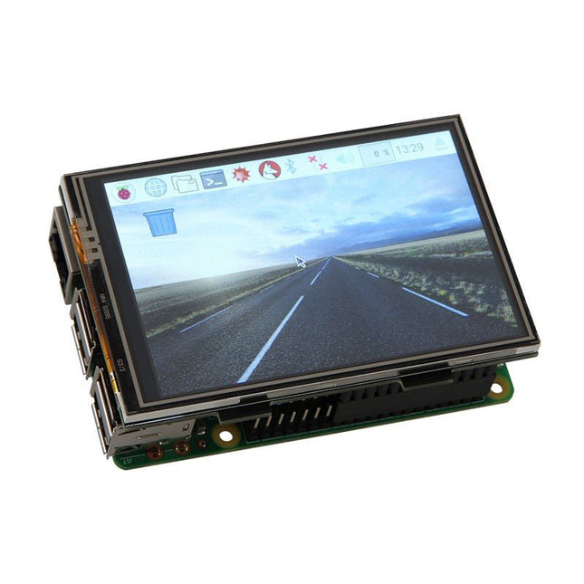
With the 3.5 inch large TFT touch screen display, you can build a mini tablet PC based on a Raspberry Pi. The display, with a maximum resolution of 480x320 pixels, is simply plugged into the existing GPIO connectors.
Specifications
Display: 3.5" (8.89 cm)
Resolution: 480x320 pixels
Touchscreen Type: Resistive
Touch screen controller: XPT2046
Colors: 65536
Backlight: LED
Connection: GPIO header
Aspect ratio: 8:5
Display Size: 85 x 56 mm
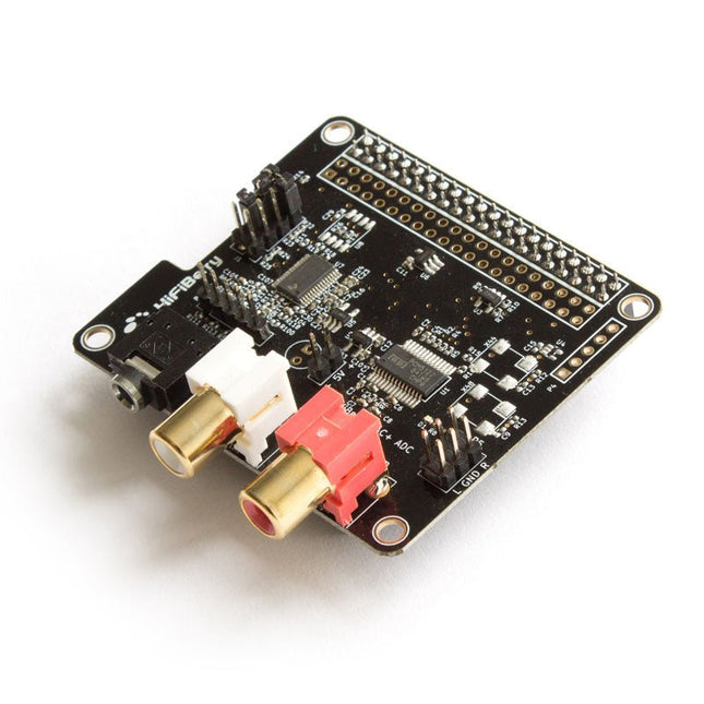
The HiFiBerry DAC+ ADC is an analog-to-digital and a digital-to-analog converter for the Raspberry Pi. This unique sound card for the Raspberry Pi is optimized for one specific use case: the best audio playback quality.
Features
Stereo input and output
Dedicated 192 kHz / 24-bit high-quality Burr-Brown DAC
Dedicated 192 kHz / 24-bit high-quality Burr-Brown ADC
Hardware volume control for DAC. The output volume can be controlled using “alsamixer” or any application that supports ALSA mixer controls.
Connects directly onto the Raspberry Pi.
No soldering required.
Compatible with all Raspberry Pi models, that have a 40-pin GPIO connector
No additional power supply required.
Three ultra-low-noise linear voltage regulators.
HAT compliant, EEPROM for automatic configuration.
Gold plated RCA output connectors.
Includes 4 M 2.5 x 12 mm spacers.
Balanced/unbalanced input connector (P6)
The 5-pin connector can be used to connect a balanced input. Please note that the balanced input has to be selected with the jumpers and will always have a 12 dB gain. It shouldn't be used with line-level inputs.
Pin 1 is on the left.
right +
right –
GND
left –
left +
Output connector (P5)
The output connector realizes connections to external components like an amplifier.
Pin 1 is on the top left.
+5 V
1
2
R
GND
3
4
GND
+5 V
5
6
L
Input gain settings (J1)
The jumper block is responsible for the input configuration. It is recommended to use the default setting without additional input gain. 32 dB gain can be used to connect dynamic microphones.
Jumpers are numbered from top to bottom.
1
2
3
4
function
1
0
0
–
0 dB gain
0
1
1
–
12 dB gain
0
1
0
–
32 dB gain
0
0
1
–
balanced input, 12 dB gain
Specifications
Maximum input voltage: 2.1 Vrms - 4.2 Vrms for balanced input
Maximum output voltage: 2.1 Vrms
ADC signal-to-noise ratio: 110 dB
DAC signal-to-noise ratio: 112 dB
ADC THD+N: -93 dB
DAC THD+N: -93 dB
Input voltage for lowest distortions: 0.8 Vrms
Input gain (configurable with Jumpers): 0 dB, 12 dB, 32 dB
Power consumption: <0.3 W
Sample rates: 44.1 kHz - 192 kHz
In order to use the HiFiBerry DAC + ADC, your Raspberry Pi Linux kernel must be at least version 4.18.12.
Click here to learn how to update the Raspberry Pi kernel
Using microphones with the DAC+ ADC
The DAC+ ADC is equipped with a stereo analogue input that can be configured for a wide range of input voltages. It performs best with line-level analogue sources. However, it is also possible to use it as a microphone input.
You can only use dynamic microphones. Microphones that require a power supply are not supported.
The microphone output voltage is very low. This means you need to amplify it. The DAC+ ADC has the necessary pre-amplifier already equipped. You will have to set the jumpers correctly.
The sound from the input won’t be played back automatically on the output. You will have to use some software that reads the input and outputs it again.
Setting the correct input amplifier settings for a microphone
By default, the input sensitivity is matched for line-level audio sources. This is done via a jumper on the J1 header.
Audio input to output
There is no direct connection between the input and the output. That leads to the input from the connected microphone to not be played back automatically. If you want to hear it on the output, you need to use the command line tool alsaloop can be used for this.
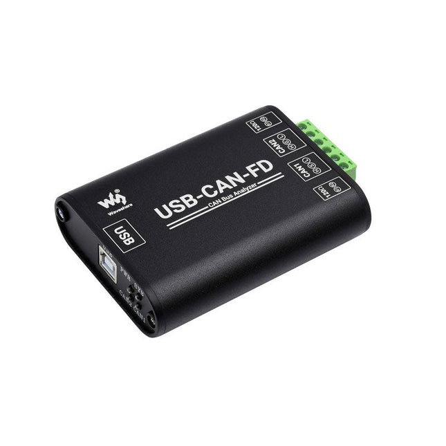
The USB-CAN-FD is an industrial-grade high-performance USB to CAN-FD adapter, CAN/CAN-FD bus communication interface card, and CAN/CAN-FD protocol data analyzer. Onboard dual independent CAN-FD interfaces with electrical isolation and multiple protection circuits. Supports Windows system, comes with drivers, CAN-FD Tools related software, secondary development examples, and tutorials. It can be connected to the PC or industrial control host via a USB port to realize transceiver control, data analysis, collection and monitoring of CAN/CAN-FD bus network. It is compact in size and easy to use, which can be used for learning and debugging of CAN/CAN-FD bus, as well as for secondary development and integration into various industrial, power communication, and intelligent control applications that require CAN/CAN-FD bus communication. Specifications Product type Industrial grade: USB to CAN-FD interface converter, CAN/CAN-FD bus communication interface card, CAN/CAN-FD protocol data analyzer USB Operating voltage 5 V (directly powered by USB port without external power supply) Connector USB-B CAN/CAN FD interface CAN/CAN FD channel Dual-channel: CAN1 and CAN2 (independent and full-isolated, isolated voltage: 3000 V DC) Connector CAN bus screw terminal (OPEN6 5.08 mm pitch) Terminal resistor Each CAN/CAN-FD channel has two built-in 120Ω terminal resistors, which can be enabled by switch Baud Rate 100Kbps~5Mbps (configurable via software) Protocol Support CAN2.0A, CAN2.0B, and ISO 11898-1 CAN-FD protocol V.1.0 Transfer speed The receiving and sending speed of each CAN/CAN-FD channel can reach 20000 frames/s and 5000 frames/s Transmit buffer 1500 frames receiving buffer and 64 frames sending buffer per channel (automatically retransmit when the transmission fails) Indicators PWR Power indicator SYS System status indicator, normally off; keeps on when there is a bus error CAN1 CAN1 channel indicator (blinking when sending and receiving data) CAN2 CAN2 channel indicator (blinking when sending and receiving data) System support Windows Windows XP/7/8/10/11 (32/64 bits); Does Not support the Linux system now, and the related drivers are under development. Operating temperature −40 to +85°C Case material Aluminum alloy case + 3D flame-retardant insulating sheets on both sides (This design can provide better protection against metal tip discharge, also improves product safety, and extends service life) Dimensions 104 x 70 x 25 mm Included Waveshare USB-CAN-FD USB-A to USB-B cable 4-pin cable Screwdriver Downloads Wiki
The PCW10A soldering mat is the ultimate solution for any soldering or repair project. Measuring 450 x 300 mm, this silicone mat provides a generous work surface that is heat-resistant up to 450°C, making it ideal for use with a range of (soldering) tools and equipment. It is the perfect size for your workbench and provides ample space for all your tools and components. The PCW10A soldering mat comes with several convenient features to make your repair work easier and more efficient. The built-in storage boxes provide a convenient place to keep your tools and components organized, while the powerful magnets hold small parts securely in place. These features ensure that you can work more efficiently and effectively, reducing the risk of lost or misplaced items. The PCW10A soldering mat also features a non-slip surface that provides a stable and secure work environment, preventing your equipment from slipping or sliding during use. Additionally, the mat is easy to clean, allowing you to maintain a hygienic workspace that is free of debris and other contaminants. In addition, the mat also features a printed grid to help you measure and cut materials accurately. Whether you are a professional technician or a DIY enthusiast, the PCW10A soldering mat is an essential tool for anyone who needs a reliable and durable work surface for their repair and soldering projects. With its durable construction, ample workspace, and convenient storage options, you can tackle any project with confidence and ease. Features Silica gel working mat (blue) Size: 450 x 300 mm Edge thickness: 6.5 mm Various magnetic sections 3 storage boxes Heat-resistant 450°C
Features
4 1/2 bit resolution (20000 Counts)
Data Logger
Multimeter
Thermometer
True RMS test supported
BLE 4.0 wireless transmission, more stable,less power consumption
Build-in offline record function
Chart and Diagram mode helps to analyze the data tendency
Flashlight function lightens the darkness
Support NCV non-contact voltage sense
Widely supported on Android, iOS, Windows
Included
OWON OW18E Multimeter
Quick Guide
Multimeter Lead
K-type Thermocouple
Bolt Driver
App Download
The Bluetooth function of this multimeter is compatible with Android-app version 1.5.8.0 or newer.
Use the QR code in the box or go to http://files.owon.com.cn/bluetooth.
The WMT-10 Inductive Wood Moisture Meter features a 2.4-inch high-definition color screen, specifically designed to cater to the needs of the wood processing industry and wood users. This advanced device provides precise measurements of wood moisture content and supports four versatile measurement modes: hardwood, softwood, plaster wall, and brick wall.
Specifications
Measurement Type
Non-destructive / Pinless / Inductive / Non-contact Testing
Display
2.4" TFT Color Screen
Resolution
0.1%
Measuring Depth (max)
17 mm
Sensor Size
40.5 x 40.5 mm
Measurement Range
Plaster Wall: 0~25%
Brick Wall: 0~43%
Softwood: 0~75%
Hardwood: 0~75%
Measurement Error
±1.5%
Humidity Alarm
Sound Alarm / Color Alarm
Auto Power Off
5/10/15 Minutes
Data Saving and Viewing
Save and view up to 30 sets of data
Power Supply
1000 mAh Lithium battery
Operating Temperature
0~40℃
Dimensions
206 x 99 x 44 mm
Weight
238 g
Included
1x FNIRSI WMT-10 Wood Moisture Meter
1x USB cable
1x Manual
Downloads
Manual
These high-precision, anti-static tweezers with black ESD coating can be used in electronics for placing SMD components when soldering and for repairing smartwatches, smartphones, tablets, PCs etc. It is ideal for picking up small components in hard to reach places.
Specifications
Length
135 mm
Width
9 mm
This Crowtail series 4G module is a high-performance LTE Cat1 wireless module. It uses the SIM A7670E communication module from Simcom and communicates through a UART interface, which enables 4G data transmission and voice communication. The module supports multiple LTE bands, including B1/B3/B5/B7/B8/B20, as well as WCDMA and GSM networks. In addition, it supports various protocols such as TCP/IP, FTP, HTTP, and multiple satellite navigation systems such as GPS, GLONASS, and BDS.
The module comes with a charging interface and can be powered by a 3.7 V lithium battery or a 5 V USB-C interface. It also has a 3.5 mm headphone jack, and by connecting a headphone with a microphone, it can be used for making and receiving phone calls. Its compact size makes it easy to integrate into various IoT devices and meet various application requirements. Furthermore, its low power consumption and reliable performance are also the reasons why it is widely used in IoT, smart home, automotive, and industrial control fields.
Features
Integrate the A7670E communication module, enabling 4G data transmission and voice communication with low power consumption and high reliability
Supports multiple LTE bands, including B1/B3/B5/B7/B8/B20, as well as WCDMA and GSM networks
Supports various protocols such as TCP/IP, FTP, HTTP, and multiple satellite navigation systems such as GPS, GLONASS, and BDS
Comes with a charging interface and a headphone jack, which can be used for making and receiving phone calls by connecting a headphone with a microphone
Small but powerful, compact size makes it easy to integrate into various IoT devices.
Specifications
Main Chip: SIM A7670E
LTE-FDD: B1/B3/B5/B7/B8/B20
GSM: 900/1800 MHz
GSM/GPRS power class
EGSM900: 4 (33 dBm ±2 dB)
DCS1800: 1 (30 dBm ±2 dB)
EDGE power class:
EGSM900: E2 (27 dBm ±3 dB)
DCS1800 : E1 (26 dBm +3 dB/-4 dB)
LTE power class: 3 (23 dBm ±7 dB)
Supply Voltage: 4 V ~ 4.2 V
Power: 3.8 V
LTE(Mbps): 10 (DL)/5 (UL)
GPRS/EDGE(Kbps): 236.8 (DL)/236.8 (UL)
Protocol: TCP/IP/IPV4/IPV6/Multi-PDP/FTP/FTPS /HTTP/HTTPS/DNS
Communication interface: USB / UART
Firmware Upgrade: USB/FOTA
Support phonebook types: SM/FD/ON/AP/SDN
Interfaces: 1x Power button, 1x BAT, 1x UART, 1x USB-C, 1x SIM Card slot
Dimensions: 35 x 50 mm
Included
1x Crowtail-4G SIM-A7670E
1x 4G GSM NB-IoT Antenna
1x GPS ceramic antenna
Downloads
Wiki
A7670 AT Command Manual
A7670 Datasheet
Source Code
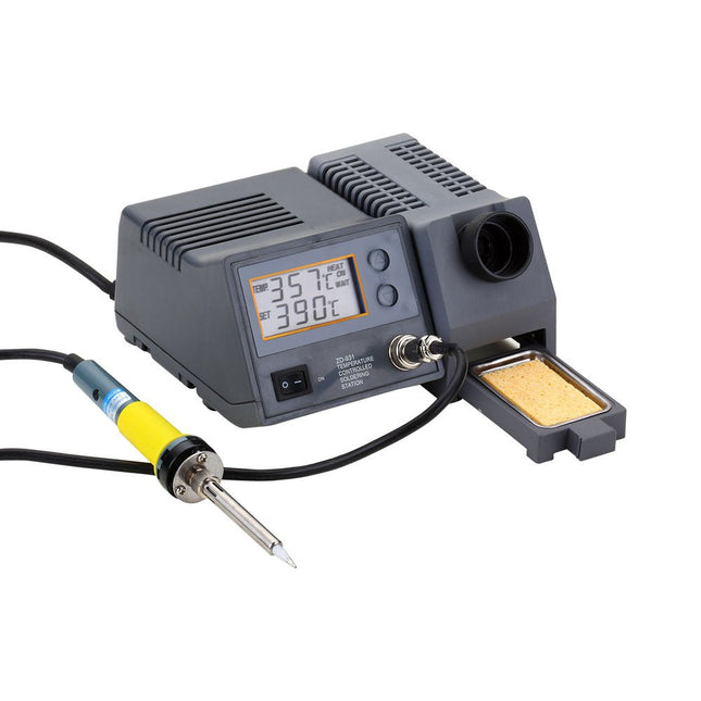
The powerful soldering station with LCD panel has been designed for a wide temperature range (from 150-450°C) and is ideal for general purpose soldering as well as specialized lead-free soldering applications. The soldering iron is controlled automatically by the microprocessor.
With its high-quality sensor the heat exchange system guarantees precise temperature control at the soldering tip. This digital temperature controlled soldering station includes a holder and cleaning sponge.
Specificaties
Operating voltage
220-240 V, 50 Hz
Power consumption
80 W
Soldering iron power
48 W
Operating voltage soldering iron
24 V
Temperature (adjustable)
150-450°C
Dimensions
195 x 87 x 165 mm
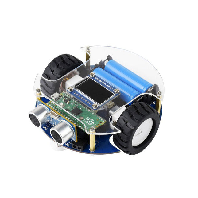
The PicoGo is a smart mobile robot based on Raspberry Pi Pico, it includes ultrasonic module, LCD module, Bluetooth module, line following module, and obstacle avoidance module, all these functions are highly integrated for easily achieving IR obstacle avoidance, auto line following, Bluetooth/IR remote control, and more. With various advanced features, it will help you fast get started with smart robot design and development.
Features
Standard Raspberry Pi Pico header, supports Raspberry Pi Pico series
Battery protection circuit: over charge/discharge protection, over current protection, short circuit protection, reverse proof, more stable and safe operating
Recharge/Discharge circuit, allows programming/debugging concurrently while recharging
5-ch infrared sensor, analog output, combined with PID algorithm, stable line tracking
Onboard multiple smart robot sensors like line tracking, obstacle avoidance, no more messy wiring
1.14-inch IPS colorful LCD display, 240 x135 pixels, 65K colors
Integrates Bluetooth module, allows teleoperations like robot movement, RGB LED display color, buzzer, etc. by using mobile phone APP
N20 micro gearmotors, with metal gears, low noise, high accuracy
Colorful RGB LED
IR obstacle avoidance
The module sends IR beam and detects objects by receiving the reflected IR beam, to easily avoid obstacles in the way.
Auto line following
Features 5-ch IR detector for sensing and analysing the black line, combined with PID algorithm for adjusting robot movement, high sensitivity, stable tracking.
Ultrasonic sensor
Ultrasonic is generally faster and easy-to-calculate, suitable for functions like real time control, and obstacle avoidance, with the industrial practical ranging accuracy, it is widely used on robot research and development.
Object tracking
The robot is able to detect front object by ultrasonic or IR, and keeps moving to track the target automatically.
IR remote control
Integrates IR receiver, so that you can control the robot to move or turn direction by sending infrared light from the remote controller.
Bluetooth remote control
Comes with mobile phone APP, allows you to use the phone to control the movement of the robot, or control its peripherals like changing LED color, making the buzzer to sound, etc.
RGB LED control
Included
1x PicoGo base board
1x PicoGo acrylic panel
1x 1.14-inch LCD Module
1x Ultrasonic sensor x1
1x IR remote controller
1x USB-A to micro-B cable 1.2 m
1x PH2.0 8-Pin cable 5 cm opposite side headers
1x Mini cross wrench sleeve
1x Screwdriver
1x Screws and standoffs pack
Required
1x Raspberry Pi Pico (pre-soldered header)
1x 5 V/3 A power supply
2x 14500 batteries
Downloads
Wiki
The RP2040 utilizes dual ARM Cortex-M0+ processors (up to 133MHz): 264kB of embedded SRAM in six banks 6 dedicated IO for SPI Flash (supporting XIP) 30 multifunction GPIO: Dedicated hardware for commonly used peripherals Programmable IO for extended peripheral support Four 12-bit ADC channels with internal temperature sensor (up to 0.5 MSa/s) USB 1.1 Host/Device functionality The RP2040 is supported with C/C++ and MicroPython cross-platform development environments, including easy access to runtime debugging. It has a UF2 boot and floating-point routines baked into the chip. The built-in USB can act as both device and host. It has two symmetric cores and high internal bandwidth, making it useful for signal processing and video. While the chip has a large internal RAM, the board includes an additional external flash chip. Features Dual Cortex M0+ processors, up to 133 MHz 264 kB of embedded SRAM in 6 banks 6 dedicated IO for QSPI flash, supporting execute in place (XIP) 30 programmable IO for extended peripheral support SWD interface Timer with 4 alarms Real-time counter (RTC) USB 1.1 Host/Device functionality Supported programming languages MicroPython C/C++
Build Trust and Convert Buyers with Technical Content
Research shows that this analytical, skeptical buyer conducts a great deal of independent research before engaging with vendors. Companies that share expertise through high-quality content on a consistent basis are not only seen as trusted resources, they also spend less per lead and achieve greater pipeline efficiency.
Content Marketing, Engineered guides you through the key steps in creating content to inform, educate, and help your technical buyers on their journey to purchase and beyond. By the time you reach the last page, you’ll be familiar with the entire end-to-end content marketing process, from planning and writing to publishing, promoting, and measuring the performance of your content.
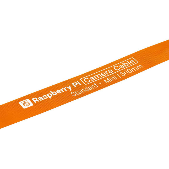
Raspberry Pi 5 provides two four-lane MIPI connectors, each of which can support either a camera or a display. These connectors use the same 22-way, 0.5 mm-pitch “mini” FPC format as the Compute Module Development Kit, and require adapter cables to connect to the 15-way, 1 mm-pitch “standard” format connectors on current Raspbery Pi camera and display products.These mini-to-standard adapter cables for cameras and displays (note that a camera cable should not be used with a display, and vice versa) are available in 200 mm, 300 mm and 500 mm lengths.