The JOY-iT R301T fingerprint sensor module is capable of image collection and algorithm calculation due to this integrated chip. Another remarkable function of the sensor is, that it can recognize the fingerprint in different conditions, for example humidity, light texture or changes of the skin. This offers a very wide range of possible applications to secure locks and doors among others. The chip can send data via UART, TTL serial and USB to the connected controller.
Specifications
Model
JP2000 sensor
Chip
32 Bit ARM Cortex-M3
Chip storage
96 kB RAM, 1 MB Flash
Power supply
4.2-6.0 V
Working current
Typical: 40 mAPeak: 50 mA
Logic level
3,3/5 V TTL Logic
Fingerprint storage capacity
3000 Prints
Matching mode
1:N Identification1:1 Verification
Adjustable security level
1 - 5 levels(default security level: 3)
False acceptance rate
< 0.001%(on security level 3)
False acceptance rate
< 0.1%(on security level 3)
Response time
Pre-treatment: < 0.45 sMatch: < 1.5 s
Baud rate support
9600 - 921600
UART communication
No parity, Stop Bit: 1
Dimensions
42 x 19 x 8 mm
Included
1x Fingerprint sensor COM-FP-R301T
1x Cable
Downloads
Datasheet
Manual
The ATmega328 Uno Development Board (Arduino Uno compatible) is a microcontroller board based on the ATmega328.
It has 14 digital input/output pins (of which 6 can be used as PWM outputs), 6 analogue inputs, a 16 MHz ceramic resonator, a USB connection, a power jack, an ICSP header and a reset button.
It contains everything needed to support the microcontroller; connect it to a computer with a USB cable or power it with a AC-to-DC adapter or battery to get started.
Specifications
Microcontroller
ATmega328
Operating voltage
5 V DC
Input voltage (recommended)
7-12 V DC
Input voltage (limits)
6-20 V DC
Digital I/O pins
14 (of which 6 provide PWM output)
Analogue input pins
6
SRAM
2 kB (ATmega328)
EEPROM
1 kB (ATmega328)
Flash memory
32 kB (ATmega328) of which 0.5 kB used by bootloader
Clock speed
16 MHz
Downloads
Manual
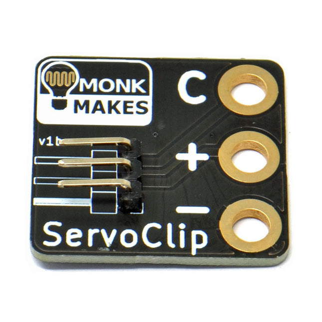
An adapter for connecting a servo meter with croc/alligator clips.
This is a handy little clip to connect a servo motor with 5.4 mm header socket using alligator clips. It is ideal for use with boards like the BBC micro:bit and Adafruit's Circuit Playground Express or Gemma.
Width: 27 mm
Height: 35 mm
Downloads
Datasheet
The EiBotBoard ('EBB') is a USB-based dual stepper motor controller board that is useful for many general purpose robotics applications. Originally designed for the EggBot project, it is the 'brain' of all current models of the EggBot, but also of the AxiDraw and WaterColorBot as well. The EBB was designed by Brian Schmalz of Schmalz Haus LLC. It is an open source (in both hardware and software), PIC18F46J50-based motor controller board. Standard features include two Allegro A4983 16X microstepping motor drivers for bipolar steppers. It also has a separate onboard regulator to power up to two hobby servo motors. It is 2.2 x 2.2 inches square (5.6 x 5.6 cm). We are currently shipping version 2.7 of the EBB, which features several improvements for reliability. Version 2.7 uses a standard USB micro connector and has a switch that by default turns off power to the pen-lift servo motor after one minute of inactivity. You can change the timeout duration or disable this feature using the serial command protocol. Specifications Motor driver ICs: Two Allegro A4983 Stepper motor type: Bipolar (2) Step size: Full, 1/2, 1/4, 1/8, 1/16 Motor connectors: Screw terminal USB jack type: Micro-B Power connector: Barrel Jack, 2.1 x 5.5 mm, center positive Voltage input range: 9-25 V DC Output current adjustment: 46 mA to 1.25 A per phase Downloads/Documentation GitHub
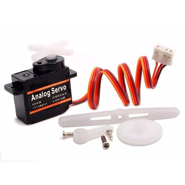
The only expendable component of the AxiDraw is the small, blue pen-lift servo motor. They do wear out over time but are straightforward to replace. For heavy duty applications, you may wish to keep a spare on hand. This replacement servo motor has been calibrated to the correct range, has the extended servo horn attached, and is ready to install. Includes a few cable ties to keep things neat. Compatible with: AxiDraw V3 AxiDraw V3/A3 AxiDraw SE/A3 AxiDraw V3 XLX Custom assembled AxiDraw models
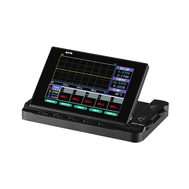
MDP-M01 is a display control module equipped with a 2.8-inch TFT display screen, the screen can be turned 90 degrees, which is convenient for users to view data and waveform. MDP-M01 can realize online display and control with MDP-P906 mini digital power supply modules and other modules of MDP system through 2.4 GHz wireless communication, and can control up to 6 sub-modules at the same time.
Specifications
Screen size
2.8' TFT
Screen resolution
240 x 320
Power
Micro USB power input, or taking power from sub-module via dedicated power cable
Input
DC 5 V/0.3 A
Other functions
Can control up to 6 sub-modulesUpgrade formware through Micro USB
Dimensions
107 x 66 x 13.6 mm
Weight
133 g
Included
1x MDP-M01 Smart Digital Monitor
1x Cable (2.5 mm jack to Micro USB)
Downloads
User Manual v3.4
Firmware v1.32
The Arduino MKR Zero is a development board for music makers! With an SD card holder and dedicated SPI interfaces (SPI1), you are able to play music files without extra hardware. The MKR Zero brings you the power of a Zero in the smaller format established by the MKR form factor. The MKR Zero board acts as a great educational tool for learning about 32-bit application development. It has an on-board SD connector with dedicated SPI interfaces (SPI1) that allows you to play with MUSIC files with no extra hardware! The board is powered by Atmel’s SAMD21 MCU, which features a 32-bit ARM Cortex M0+ core. The board contains everything needed to support the microcontroller; simply connect it to a computer with a micro-USB cable or power it by a LiPo battery. The battery voltage can also be monitored since a connection between the battery and the analog converter of the board exists. Specifications Microcontroller SAMD21 ARM Cortex-M0+ 32-bit low power Board power supply (USB/VIN) 5 V Supported battery Li-Po single cell, 3.7 V, 700 mAh minimum DC current for 3.3 V pin 600 mA DC current for 5 V pin 600 mA Circuit operating voltage 3.3 V Digital I/O pins 22 PWM pins 12 (0, 1, 2, 3, 4, 5, 6, 7, 8, 10, A3 - or 18 -, A4 -or 19) UART 1 SPI 1 I²C 1 Analog input pins 7 (ADC 8/10/12 bit) Analog output pins 1 (DAC 10 bit) External interrupts 10 (0, 1, 4, 5, 6, 7, 8, A1 -or 16-, A2 - or 17) DC current per I/O pin 7 mA Flash memory 256 KB Flash memory for bootloader 8 KB SRAM 32 KB EEPROM No Clock speed 32.768 kHz (RTC), 48 MHz LED_BUILTIN 32 Downloads Datasheet Eagle Files Schematics Fritzing Pinout
Portenta H7 Lite allows you to build your next smart project.
Ever wanted an automated house? Or a smart garden? Well, now it’s easy with the Arduino IoT Cloud compatible boards. It means: you can connect devices, visualize data, control and share your projects from anywhere in the world.
The Arduino Pro Portenta H7 Lite is very similar to the Portenta H7, that simultaneously can run high level code along with real time tasks thanks to its two processors. It is, for example, possible to execute Arduino compiled code along with MicroPython one and have both cores to communicate with one another. However, the H7 Lite is a low-cost board with H7 functionalities that can be configured to specific use cases.
Features
Dual Core – Two best-in-class processors in one, running parallel tasks
AI on the edge – So powerful it can run AI state machines
Customization – The board is highly customizable in volumes
High-level programming language support (Micropython)
The Portenta H7 Lite offers twofold functionality: it can run either like any other embedded microcontroller board, or as the main processor of an embedded computer.
For example, use the Portenta Vision Shield to transform your H7 Lite into an industrial camera capable of performing real-time machine learning algorithms on live video feeds. As the H7 Lite can easily run processes created with TensorFlow Lite, you could have one of the cores computing a computer vision algorithm on the fly, while the other carries out low-level operations like controlling a motor or acting as a user interface.
Solutions
High-end industrial machinery
Laboratory equipment
Computer vision
PLCs
Robotics controllers
Mission-critical devices
High-speed booting computation (ms)
Two Parallel Cores
The Portenta H7 Lite’s main processor is the STM32H747 dual core including a Cortex-M7 running at 480 MHz and a Cortex-M4 running at 240 MHz. The two cores communicate via a Remote Procedure Call mechanism that allows calling functions on the other processor seamlessly. Both processors share all the in-chip peripherals and can run:
Arduino sketches on top of the ARM Mbed OS
Native Mbed applications
MicroPython / JavaScript via an interpreter
TensorFlow Lite
A New Standard for Pinouts
The Portenta family adds two 80-pin high-density connectors at the bottom of the board. This ensures scalability for a wide range of applications: simply upgrade your Portenta board to the one suiting your needs.
USB-C Multipurpose Connector
The board’s programming connector is a USB-C port that can also be used to power the board, as a USB Hub, or to deliver power to OTG connected devices.
Arduino IoT Cloud
Use your Portenta board on Arduino’s IoT Cloud, a simple and fast way to ensure secure communication for all of your connected Things.
Specifications
Microcontroller
STM32H747XI Dual Cortex-M7+M4 32-bit low power ARM MCU (datasheet)
Secure element (default)
Microchip ATECC608
Board power supply (USB/VIN)
5 V
Supported battery
Li-Po Single Cell, 3.7 V, 700 mAh Minimum (integrated charger)
Circuit operating voltage
3.3 V
Current consumption
2.95 μA in Standby mode (Backup SRAM OFF, RTC/LSE ON)
Timers
22x timers and watchdogs
UART
4x ports (2 with flow control)
Ethernet PHY
10 / 100 Mbps (through expansion port only)
SD card
Interface for SD card connector (through expansion port only)
Operational temperature
-40 °C to +85 °C
MKR headers
Use any of the existing industrial MKR shields on it
High-density connectors
Two 80-pin connectors will expose all of the board's peripherals to other devices
Camera interface
8-bit, up to 80 MHz
ADC
3x ADCs with 16-bit max. resolution (up to 36 channels, up to 3.6 MSPS)
DAC
2x 12-bit DAC (1 MHz)
USB-C
Host / Device, High / Full Speed, Power delivery
Downloads
Datasheet
Schematics
SMA Straight Plug to SMA Straight Plug, 76.2 mm
Specifications
Frequency range
0 to 18 GHz VSWR (≤1.35)
Insertion loss
≤0,22 db
Body
Brass Nickel
Centre contact
Brass Gold
Insulator
PTFE
Features
Ideally suited for mounting printed circuit boards.
Perfect for applications where parts, sensors, or indicators need to be visible.
Almost totally transparent to infrared devices.
Integral card guides accept 1.5 mm (0.062") P.C. cards.
Lap joint construction provides protection against access of dust and splashing water.
Designed to meet IP54.
Molded from flame retardant, easy to machine, translucent polycarbonate. Material carries a UL flammability rating of UL 94 V-2.
Lid is secured with M3x10 mm phillips machine screws, threaded into integral brass bushings.
Part number: 1591CTRD
Dimensions: 119 x 66 x 36 mm
Arduino MKR NB 1500 allows you to build your next smart project.
Ever wanted an automated house? Or a smart garden? Well, now it’s easy with the Arduino IoT Cloud compatible boards. It means: you can connect devices, visualize data, control and share your projects from anywhere in the world. Whether you’re a beginner or a pro, we have a wide range of plans to make sure you get the features you need.
Add Narrowband communication to your project with the MKR NB 1500. It's the perfect choice for devices in remote locations without an Internet connection, or in situations in which power isn't available like on-field deployments, remote metering systems, solar-powered devices, or other extreme scenarios.
The board's main processor is a low power ARM Cortex-M0 32-bit SAMD21, like in the other boards within the Arduino MKR family. The Narrowband connectivity is performed with a module from u-blox, the SARA-R410M-02B, a low power chipset operating in the de different bands of the IoT LTE cellular range. On top of those, secure communication is ensured through the Microchip ECC508 crypto chip. Besides that, the pcb includes a battery charger, and a connector for an external antenna.
This board is designed for global use, providing connectivity on LTE's Cat M1/NB1 bands 1, 2, 3, 4, 5, 8, 12, 13, 18, 19, 20, 25, 26, 28. Operators offering service in that part of the spectrum include: Vodafone, AT&T, T-Mobile USA, Telstra, and Verizon, among others.
Specifications
The Arduino MKR NB 1500 is based on the SAMD21 microcontroller.
Microcontroller
SAMD21 Cortex-M0+ 32-bit low power ARM MCU (datasheet)
Radio module
u-blox SARA-R410M-02B (datasheet summary)
Secure element
ATECC508 (datasheet)
Board power supply (USB/VIN)
5 V
Supported battery
Li-Po Single Cell, 3.7 V, 1500 mAh Minimum
Circuit operating voltage
3.3 V
Digital I/O pins
8
PWM pins
13 (0 .. 8, 10, 12, 18 / A3, 19 / A4)
UART
1
SPI
1
I²C
1
Analog input pins
7 (ADC 8/10/12 bit)
Analog output pins
1 (DAC 10 bit)
External interrupts
8 (0, 1, 4, 5, 6, 7, 8, 16 / A1, 17 / A2)
DC current per I/O pin
7 mA
Flash memory
256 KB (internal)
SRAM
32 KB
EEPROM
No
Clock speed
32.768 kHz (RTC), 48 MHz
LED_BUILTIN
6
USB
Full-speed USB device and embedded host
Antenna gain
2 dB
Carrier frequency
LTE bands 1, 2, 3, 4, 5, 8, 12, 13, 18, 19, 20, 25, 26, 28
Power class (radio)
LTE Cat M1 / NB1: Class 3 (23 dBm)
Data rate (LTE M1 halp-duplex)
UL 375 kbps / DL 300 kbps
Data rate (LTE NB1 full-duplex)
UL 62.5 kbps / DL 27.2 kbps
Working region
Multiregion
Device location
GNSS via modem
Power consumption (LTE M1)
min 100 mA / max 190 mA
Power consumption (LTE NB1)
min 60 mA / max 140 mA
SIM card
MicroSIM (not included with the board)
Dimensions
67.6 x 25 mm
Weight
32 g
Downloads
Eagle Files
Schematics
Pinout
This ultrasonic distance sensor (ME007-ULA V1) offers high performance with a robust, waterproof probe. Operating on the principle of ultrasonic echo ranging, the sensor determines the distance to a target by measuring the time elapsed between sending a pulse and receiving the echo. Its non-contact design allows it to detect a wide range of materials, including transparent or non-ferrous objects, metals, non-metals, liquids, solids, and powders.
Specifications
Detecting Distance
27~800 cm
Output Interface
RS232, Voltage Analog
Operating Voltage
5-12 V
Average Current
<10 mA
Operating Temperature
−15~60°C
Dimensions
60 x 43 x 31 mm
The Whadda E12 is a high-quality carbon film resistor set comprising 610 pieces, with 10 pieces for each of the 61 standard E12 series values ranging from 10 Ω to 1 MΩ. Each resistor has a power rating of 0.25 W, a tolerance of 5%, and can operate within a temperature range of -55°C to 155°C. The maximum operating voltage is 250 V.
These resistors are suitable for applications in TVs, audio and video equipment, telephone receivers, communication systems, instrumentation, and home appliances.
When playing a board game, do you find it annoying when you push away all the pawns with the dice? Or when friends try to cheat by manipulating the dice? With this soldering kit, this is a thing of the past. Instead of pressing a button, you activate this microprocessor-controlled dice by shaking. The 7 flashing LEDs run out slowly and the final combination is displayed flashing. The kit works with one CR2025 or one CR2032 button cell (not included).
Downloads
Manual
Excellent quality, high-torque 'NEMA 17' bipolar stepper motor for all of your motion control needs. Features a 5 mm precision ground shaft with a machined flat. Wiring harness included, various wire lengths available. Useful for all kinds of robotics projects! For example, this is the same stepper motor used in the EggBot kit and AxiDraw. Specifications Motor type: Bipolar stepper motor (4-wire) 1.8 degree step angle (200 steps per revolution) 5 mm output shaft, w/ machined flat 24 mm (0.95 inches) shaft length from screw face plate NEMA 17 form factor 31 mm (1.22 inches) mounting hole distance Mounting screw type: M3 with 3.5 mm min. thread depth 42 mm (1.65 inch) square body size Coil voltage 3.1 V Current 1 A per phase Winding resistance 3.1 ohms per phase Holding torque 1440 g*cm Leads are tinned, wrapped in heat shrink tubing (black or gray) Wire colors: Red and Yellow for the first coil, green and gray for the second coil. Downloads Datasheet
The MLX90640 SparkFun IR Array Breakout features a 32×24 array of thermopile sensors generating, in essence, a low resolution thermal imaging camera. With this breakout you can observe surface temperatures from a decent distance away with an accuracy of ±1.5°C (best case). This board communicates via I²C using the Qwiic system developed by Sparkfun, which makes it easier to operate the breakout. However, there are still 0.1'-spaced pins in case you favour using a breadboard.
The SparkFun Qwiic connect system is an ecosystem of I²C sensors, actuators, shields and cables that make prototyping faster and helps you avoid errors. All Qwiic-enabled boards use a common 1 mm pitch, 4-pin JST connector. This reduces the amount of required PCB space, and polarized connections help you connect everything correctly.
This specific IR Array Breakout provides a 110°×75° field of view with a temperature measurement range of -40~300°C. The MLX90640 IR Array has pull up resistors attached to the I²C bus; both can be removed by cutting the traces on the corresponding jumpers on the back of the board. Please be aware that the MLX90640 requires complex calculations by the host platform so a regular Arduino Uno (or equivalent) doesn't have enough RAM or flash to complete the complex computations required to turn the raw pixel data into temperature data. You will need a microcontroller with 20,000 bytes or more of RAM.
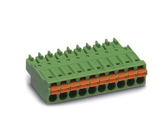
This 14-way MonoDAQ-compatible connector allows the user to create, reuse and archive test fixtures instead of rewiring the connector furnished with the MonoDAQ everytime a measurement or test has to be repeated. Helps the user to build a library of plug-and-play test setups. Features Time saving push-in connection, tools not required Defined contact force ensures that contact remains stable over the long term Intuitive use through colour coded actuation lever Operation and conductor connection from one direction enable integration into front of device All necessary technical data can be found here.
The CubeCell series is designed primarily for LoRa/LoRaWAN node applications.
Built on the ASR605x platform (ASR6501, ASR6502), these chips integrate the PSoC 4000 series MCU (ARM Cortex-M0+ Core) with the SX1262 module. The CubeCell series offers seamless Arduino compatibility, stable LoRaWAN protocol operation, and straightforward connectivity with lithium batteries and solar panels.
The HTCC-AB02 is a developer-friendly board, ideal for quickly testing and validating communication solutions.
Features
Arduino compatible
Based on ASR605x (ASR6501, ASR6502), those chips are already integrated the PSoC 4000 series MCU (ARM Cortex M0+ Core) and SX1262
LoRaWAN 1.0.2 support
Ultra low power design, 3.5 uA in deep sleep
Onboard SH1.25-2 battery interface, integrated lithium battery management system (charge and discharge management, overcharge protection, battery power detection, USB/battery power automatic switching)
Good impendence matching and long communication distance
Onboard solar energy management system, can directly connect with a 5.5~7 V solar panel
Micro USB interface with complete ESD protection, short circuit protection, RF shielding, and other protection measures
Integrated CP2102 USB to serial port chip, convenient for program downloading, debugging information printing
Onboard 0.96-inch 128x64 dot matrix OLED display, which can be used to display debugging information, battery power, and other information
Specifications
Main Chip
ASR6502 (48 MHz ARM Cortex-M0+ MCU)
LoRa Chipset
SX1262
Frequency
863~870 MHz
Max. TX Power
22 ±1 dBm
Max. Receiving Sensitivity
−135 dBm
Hardware Resource
2x UART1x SPI2x I²C1x SWD3x 12-bit ADC input8-channel DMA engine16x GPIO
Memory
128 Kb FLASH16 Kb SRAM
Power consumption
Deep sleep 3.5 uA
Interfaces
1x Micro USB1x LoRa Antenna (IPEX)2x (15x 2.54 Pin header) + 3x (2x 2.54 Pin header)
Battery
3.7 V lithium battery (power supply and charging)
Solar Energy
VS pin can be connected to 5.5~7 V solar panel
USB to Serial Chip
CP2102
Display
0.96" OLED (128 x 64)
Operating temperature
−20~70°C
Dimensions
51.9 x 25 x 8 mm
Included
1x CubeCell HTCC-AB02 Development Board
1x Antenna
1x 2x SH1.25 battery connector
Downloads
Datasheet
Schematic
Quick start
GitHub
Valentine's Hearts, 28 blinking LEDs, romantic LED lighting Valentine's Hearts – 28 blinking LEDs for a romantic atmosphere. The perfect Valentine's gift to express your love. Battery-powered and portable, ideal for Valentine's Day.
Downloads
Manual
4 LEDs and 4 push buttons ensure hours of fun. Repeat the combination, harder and harder, faster and faster. The microprocessor-controlled game has 4 different difficulty levels and low consumption. The sound and/or LED indication are adjustable. To save the three 1.5 V AA batteries (not included), the kit automatically switches itself off when not in use.
Downloads
Manual
Waveshare Core3S500E is an FPGA core board that features an XC3S500E device onboard supporting further expansion.
Features
Onboard 1x XCF04S
Integrated FPGA basic circuit, such as clock circuit
Onboard nCONFIG button, RESET button, 4x LEDs
All the I/O ports are accessible on the pin headers
Onboard JTAG debugging/programming interface
2.0 mm header pitch design, suitable for being plugged-in your application system
Downloads
Wiki
Reinforcing its commitment to widening the accessibility to and innovation in the area of deep learning, NVIDIA has created a free, self-paced, online Deep Learning Institute (DLI) course, “Getting Started on AI with Jetson Nano.” The course's goal is to build foundational skills to enable anyone to get creative with the Jetson Developer Kit. Please be aware that this kit is for those who already own a Jetson Nano Developer Kit and want to join the DLI Course. A Jetson Nano is not included in this kit.
Included in this kit is everything you will need to get started in the “Getting Started on AI with Jetson Nano” (except for a Jetson Nano, of course), and you will learn how to
Set up your Jetson Nano and camera
Collect image data for classification models
Annotate image data for regression models
Train a neural network on your data to create your own models
Run inference on the Jetson Nano with the models you create
The NVIDIA Deep Learning Institute offers hands-on training in AI and accelerated computing to solve real-world problems. Developers, data scientists, researchers, and students can get practical experience powered by GPUs in the cloud and earn a competency certificate to support professional growth. They offer self-paced, online training for individuals, instructor-led workshops for teams, and downloadable course materials for university educators.
Included
32 GB microSD Card
Logitech C270 Webcam
Power Supply 5 V, 4 A
USB Cable - microB (Reversible)
2-Pin Jumper
Please note: Jetson Nano Developer Kit not included.
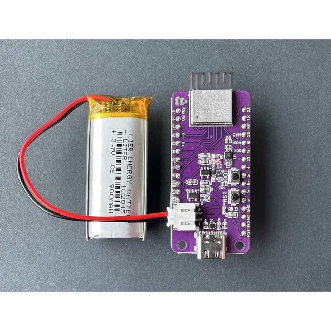
Enhance your ESP32 WiFi Color Display Kit Grande with this high-quality 900 mAh rechargeable lithium-polymer battery!
Designed to provide long-lasting power, this battery ensures your projects remain portable and efficient. With its compact size and lightweight design, it’s the perfect accessory for any DIY electronics enthusiast. The battery offers reliable performance, easy integration, and safe, stable power supply, making it ideal for extended use in a variety of applications.
900 mAh LiPo battery
JST Connector, fitting ePulse Feather
Here you will find all kinds of parts, components and accessories you will need in various projects, starting from simple wires, sensors and displays to already pre-assembled modules and kits.