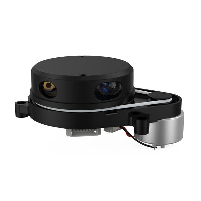
YDLIDAR X4PRO is a 360 degrees two-dimensional rangefinder. Based on the principle of triangulation, it is equipped with related optics, electricity, and algorithm design to achieve high-frequency and high-accuracy distance measurement. The mechanical structure rotates 360 degrees to continuously output the angle information as well as the point cloud data of the scanning environment while ranging.
Features
360 degrees omnidirectional scanning ranging distance measurement
Small distance error, stable performance and high accuracy
Wide ranging distance
Strong resistance to ambient light interference
Low power consumption, small size and long service life
Laser power meets Class I laser safety standards
Adjustable motor speed, scanning frequency is 6~12 Hz
High-speed ranging, ranging frequency up to 5 kHz
Applications
Robot navigation and obstacle avoidance
Robot ROS teaching and research
Regional security
Environmental scanning and 3D reconstruction
Navigation and obstacle avoidance of robot vacuum cleaner/ROS Learning robot
Specifications
Range Frequency
5000 Hz
Scan Frequency
6-12 Hz
Range Distance
0.12-10 m
Scan Angle
360°
Angle Resolution
0.43-0.85°
Dimensions
110.6 x 71.1 x 52.3 mm
Downloads
Datasheet
User Manual
Development Manual
SDK
Tool
ROS
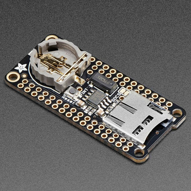
This FeatherWing will make it easy to add data logging to any Feather Board you might have. You get both an I²C real-time clock (PCF8523) with 32 KHz crystal and battery backup, and a microSD socket that connects to the SPI port pins (+ extra pin for CS). Note: FeatherWing doesn't come with a microSD card. A CR1220 coin cell is required to use the RTC battery-backup capabilities. If you're not using the RTC part of the FeatherWing, a battery is not required. To talk to the microSD card socket Arduino's default SD library is recommended. Some light soldering is required to attach the headers onto the Wing. Pinouts Power pins On the bottom row, the 3.3 V (second from left) and GND (fourth from left) pin are used to power the SD card and RTC (to take a load off the coin cell battery when main power is available) RTC & I²C Pins In the top right, SDA (rightmost) and SCL (to the left of SDA) are used to talk to the RTC chip.
SCL - I²C clock pin to connect to your microcontroller's I2C clock line. This pin has a 10 kΩ pull-up resistor to 3.3 V
SDA - I²C data pin to connect to your microcontroller's I2C data line. This pin has a 10 kΩ pull-up resistor to 3.3 V There's also a breakout for INT which is the output pin from the RTC. It can be used as an interrupt output or it could also be used to generate a square wave. Note that this pin is an open drain - you must enable the internal pull-up on whatever digital pin it is connected to. SD & SPI Pins Starting from the left you've got SPI Clock (SCK) - output from feather to wing SPI Master Out Slave In (MOSI) - output from feather to wing SPI Master In Slave Out (MISO) - input from wing to feather These pins are in the same location on every Feather. They are used for communicating with the SD card. When the SD card is not inserted, these pins are completely free. MISO is tri-stated whenever the SD CS (chip select) pin is pulled high
This carrier board combines a 2.4" TFT display, six addressable LEDs, onboard voltage regulator, a 6-pin IO connector, and microSD slot with the M.2 pin connector slot so that it can be used with compatible processor boards in our MicroMod ecosystem. We've also populated this carrier board with Atmel's ATtiny84 with 8kb of programmable flash. This little guy is preprogrammed to communicate with the processor over I²C to read button presses.
Features
M.2 MicroMod Connector
240 x 320 pixel, 2.4" TFT display
6 Addressable APA102 LEDs
Magnetic Buzzer
USB-C Connector
3.3 V 1 A Voltage Regulator
Qwiic Connector
Boot/Reset Buttons
RTC Backup Battery & Charge Circuit
microSD
Phillips #0 M2.5 x 3 mm screw included
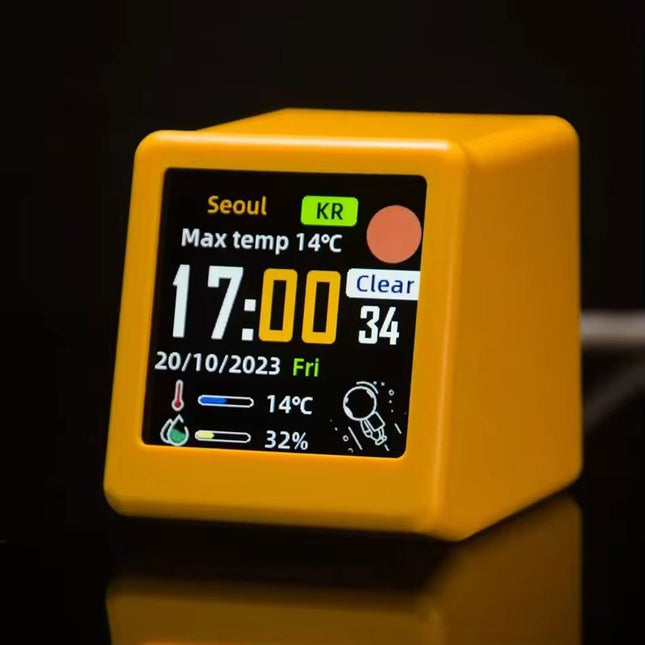
This portable WiFi weather station is the perfect blend of functionality and style, offering real-time updates on temperature, humidity, and time – all at a single glance.
Featuring a clear digital display, the station ensures that weather and time data are always easy to read and understand. Its minimalist design integrates seamlessly into any environment, adding a touch of modern sophistication without drawing unnecessary attention.
Features
Multi-Function Display: Shows weather, atmospheric pressure, min/max temperature, wind speed, city, country/region, date, day of the week, outdoor temperature & humidity – all at a glance.
Custom GIF Animations: Upload your own GIFs for a personalized display experience.
WiFi Connectivity: Automatically connects to the Internet to retrieve real-time weather and time data.
Power Supply: USB-C
Durable Plastic Casing
Dimensions: 45 x 35 x 40 mm
The Sparkfun Qwiic GPIO is an I²C device based around the TCA9534 I/O Expander IC from Texas Instruments. The board adds eight IO pins that you can read and write just like any other digital pin on your controller. The details of the I²C interface have been taken care of in an Arduino library so you can call functions similar to Arduino's pinMode and digitalWrite, allowing you to focus on your creation! The TCA9534's pins are broken out to easy-to-use latch terminals; never screw another wire into place! The terminals are relatively roomy themselves, so feel free to latch multiple wires into a ground or power terminal. With three customizable address jumpers, you can have up to eight Qwiic GPIO boards connected on a single bus allowing upwards of 64 additional GPIO pins! The default I²C is 0x27 and can be changed by adjusting the jumpers on the board's back. Features Eight Configurable GPIO Pins Available I²C Address: 0x27 (Default) Hardware address pins allow up to eight boards on a single bus Input Polarity Inversion Register Control each I/O pin individually or all at once Open-Drain Active-Low Interrupt Output 2x Qwiic Connectors Dimensions: 60.96 x 38.10 mm
The LILYGO T-Display-S3 Long is a versatile development board powered by the ESP32-S3R8 dual-core LX7 microprocessor. It features a 3.4-inch capacitive touch TFT LCD with a resolution of 180x640 pixels, providing a responsive interface for various applications.
This board is ideal for developers seeking a compact yet powerful solution for projects requiring touch input and wireless communication. Its compatibility with popular programming environments ensures a smooth development experience.
Specifications
MCU
ESP32-S3R8 Dual-core LX7 microprocessor
Wireless Connectivity
Wi-Fi 802.11, BLE 5 + BT Mesh
Programming Platform
Arduino IDE, VS Code
Flash
16 MB
PSRAM
8 MB
Bat voltage detection
IO02
Onboard functions
Boot + Reset Button, Battery Switch
Display
3.4" Capacitive Touch TFT LCD
Color depth
565, 666
Resolution
180 x 640 (RGB)
Working power supply
3.3 V
Interface
QSPI
Included
1x T-Display S3 Long
1x Power cable
2x STEMMA QT/Qwiic interface cable (P352)
1x Female pin (double row)
Downloads
GitHub
The Power Delivery Board uses a standalone controller to negotiate with the power adapters and switch to a higher voltage other than just 5V. This uses the same power adapter for different projects rather than relying on multiple power adapters to provide different output; it can deliver the board as part of SparkFun’s Qwiic connect system, so you won’t have to do any soldering to figure out how things are oriented.
The SparkFun Power Delivery Board takes advantage of the power delivery standard using a standalone controller from STMicroelectronics, the STUSB4500. The STUSB4500 is a USB power delivery controller that addresses sink devices. It implements a proprietary algorithm to negotiate a power delivery contract with a source (i.e. a power delivery wall wart or power adapter) without the need for an external microcontroller. However, you will need a microcontroller to configure the board. PDO profiles are configured in an integrated non-volatile memory. The controller does all the heavy lifting of power negotiation and provides an easy way to configure over I²C.
To configure the board, you will need an I²C bus. The Qwiic system makes it easy to connect the Power Delivery board to a microcontroller. Depending on your application, you can also connect to the I²C bus via the plated through SDA and SCL holes.
Features
Input and output voltage range of 5-20V
Output current up to 5A
Three configurable power delivery profiles
Auto-run Type-C™ and USB PD sink controller
Certified USB Type-C™ rev 1.2 and USB PD rev 2.0 (TID #1000133)
Integrated VBUS voltage monitoring
Integrated VBUS switch gate drivers (PMOS)
LuckFox Pico Mini is a compact Linux micro development board based on the Rockchip RV1103 chip, providing a simple and efficient development platform for developers. It supports a variety of interfaces, including MIPI CSI, GPIO, UART, SPI, I²C, USB, etc., which is convenient for quick development and debugging.
Features
Single-core ARM Cortex-A7 32-bit core with integrated NEON and FPU
Built-in Rockchip self-developed 4th generation NPU, features high computing precision and supports int, int8, and int16 hybrid quantization. The computing power of int8 is 0.5 TOPS, and up to 1.0 TOPS with int4
Built-in self-developed third-generation ISP3.2, supports 4-Megapixel, with multiple image enhancement and correction algorithms such as HDR, WDR, multi-level noise reduction, etc.
Features powerful encoding performance, supports intelligent encoding mode and adaptive stream saving according to the scene, saves more than 50% bit rate of the conventional CBR mode so that the images from camera are high-definition with smaller size, double the storage space
Built-in RISC-V MCU supports low power consumption and fast start-up, supports 250 ms fast picture capture and loading Al model library at the same time to realize face recognition "in one second"
Built-in 16-bit DRAM DDR2, which is capable of sustaining demanding memory bandwidths
Integrated with built-in POR, audio codec and MAC PHY
Specifications
Processor
ARM Cortex-A7, single-core 32-bit CPU, 1.2 GHz, with NEON and FPU
NPU
Rockchip 4th-gen NPU, supports int4, int8, int16; up to 1.0 TOPS (int4)
ISP
Third-gen ISP3.2, up to 4 MP input at 30fps, HDR, WDR, noise reduction
RAM
64 MB DDR2
Storage
128 MB SPI NAND Flash
USB
USB 2.0 Host/Device via Type-C
Camera Interface
MIPI CSI 2-lane
GPIO Pins
17 GPIO pins
Power Consumption
Low power, RISC-V MCU for fast startup
Dimensions
28 x 21 mm
Downloads
Wiki
The EC200U-EU C4-P01 development board features the EC200U-EU LTE Cat 1 wireless communication module, offering a maximum data rate of up to 10 Mbps for downlink and 5 Mbps for uplink. It supports multi-mode and multi-band communication, making it a cost-effective solution.
The board is designed in a compact and unified form factor, compatible with the Quectel multi-mode LTE Standard EC20-CE. It includes an onboard USB-C port, allowing for easy development with just a USB-C cable.
Additionally, the board is equipped with a 40-pin GPIO header that is compatible with most Raspberry Pi HATs.
Features
Equipped with EC200U-EU LTE Cat 1 wireless communication module, multi-mode & multi-band support
Onboard 40-Pin GPIO header, compatible with most Raspberry Pi HATs
5 LEDs for indicating module operating status
Supports TCP, UDP, PPP, NITZ, PING, FILE, MQTT, NTP, HTTP, HTTPS, SSL, FTP, FTPS, CMUX, MMS protocols, etc.
Supports GNSS positioning (GPS, GLONASS, BDS, Galileo, QZSS)
Onboard Nano SIM card slot and eSIM card slot, dual card single standby
Onboard MIPI connector for connecting MIPI screen and is fully compatible with Raspberry Pi peripherals
Onboard camera connector, supports customized SPI cameras with a maximum of 300,000 pixels
Provides tools such as QPYcom, Thonny IDE plugin, and VSCode plugin, etc. for easy learning and development
Comes with online development resources and manual (example in QuecPython)
Specifications
Applicable Regions
Europe, Middle East, Africa, Australia, New Zealand, Brazil
LTE-FDD
B1, B3, B5, B7, B8, B20, B28
LTE-TDD
B38, B40, B41
GSM / GPRS / EDGE
GSM: B2, B3, B5, B8
GNSS
GPS, GLONASS, BDS, Galileo, QZSS
Bluetooth
Bluetooth 4.2 (BR/EDR)
Wi-Fi Scan
2.4 GHz 11b (Rx)
CAT 1
LTE-FDD: DL 10 Mbps; UL 5 Mbps
LTE-TDD: DL 8.96 Mbps; UL 3.1 Mbps
GSM / GPRS / EDGE
GSM: DL 85.6 Kbps; UL 85.6 Kbps
USB-C Port
Supports AT commands testing, GNSS positioning, firmware upgrading, etc.
Communication Protocol
TCP, UDP, PPP, NITZ, PING, FILE, MQTT, NTP, HTTP, HTTPS, SSL, FTP, FTPS, CMUX, MMS
SIM Card
Nano SIM and eSIM, dual card single standby
Indicator
P01: Module Pin 1, default as EC200A-XX PWM0
P05: Module Pin 5, NET_MODE indicator
SCK1: SIM1 detection indicator, lights up when SIM1 card is inserted
SCK2: SIM2 detection indicator, lights up when SIM2 card is inserted
PWR: Power indicator
Buttons
PWK: Power ON/OFF
RST: Reset
BOOT: Forcing into firmware burning mode
USB ON/OFF: USB power consumption detection switch
Antenna Connectors
LTE main antenna + DIV / WiFi (scanning only) / Bluetooth antenna + GNSS antenna
Operating Temperature
−30~+75°C
Storage Temperature
−45~+90°C
Downloads
Wiki
Quectel Resources
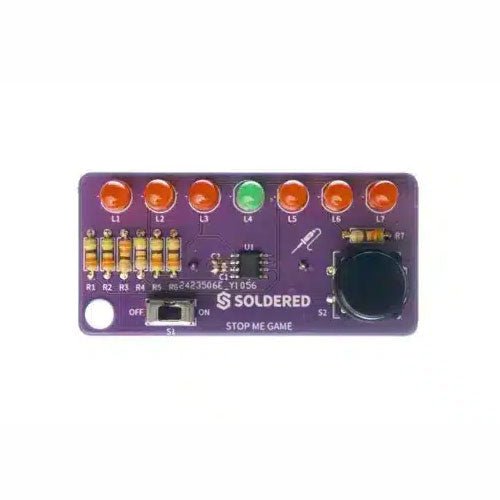
If you are looking for a simple way to learn soldering, or just want to make a small gadget that you can carry, this set is a great opportunity. Stop me game is an educational kit which teaches you how to solder, and in the end, you get to have your own small game. The LEDs go up and down, and your goal is to press the button as soon as the green LED turns on. With every correct answer, the game gets a bit harder – the time you have to press the button shortens. How many correct answers can you get?
It’s based on ATtiny404 microcontroller, programmed in Arduino. At its back, you’ll find CR2032 battery which makes the kit portable. There’s keychain holder as well. Soldering process is easy enough based on the mark on the PCB.
Included
1x PCB
1x ATtiny404 microcontroller
7x LEDs
1x Pushbutton
1x Switch
7x Resistors (330 ohm)
1x CR2032 battery holder
1x Battery CR2032
1x Keychain holder
After power on, YDLIDAR G4 start rotating and scanning the environment around it. The scanning distance is 16 m and the device offers a scanning rate of 9,000 times per second.
It makes detailed examinations of its environment and can locate the smallest of objects surrounding it. Featuring a high-precision brushless motor and encoder disc mounted on bearings, it rotates smoothly and has a service life of up to 500,000 hours of operation.
The G4 is an inexpensive solution for projects that require obstacle detection, obstacle avoidance, and/or simultaneous localization and mapping (SLAM). All YDLIDAR products are ROS ready.
Features
360 degree 2D range scanning
Stable performance, high precision
16 m range
Strong resistance to environmental light interference
Brushless motor drive, stable performance
FDA Laser safety standard Class I
360 degree omnidirectional scanning, 5-12 Hz adaptive scanning frequency
OptoMagnetic technology
Wireless data communication
Scanning rate of 9000 Hz
Downloads
Datasheet
User Manual
Development Manual
SDK
Tool
ROS
The SDS011 sensor determines the dust particle concentration in the air using the scattered light method.
The USB-UART adapter also allows the sensor to be read out directly via USB port on a computer.
Specifications
Interface
UART (3.3 V level)
Resolution
0.3 µg/m3
Response time
< 10s
Other feature
Integrated fan
Current in idle
< 4 mA
Supply current
70 mA
Operating voltage
5 V
Dimensions
70 x 70 x 24 mm
Weight
70 g
Included
1x SDS011 dust sensor
1x Connection cable
1x USB-UART adapter
Downloads
Datasheet
Manual
The Motorino board is an extension-board to control and use up to 16 PWM-controlled 5V-Servo-motors. The included clock generator ensures a very precise PWM signal and a very precise positioning. The board has 2 inputs for voltage from 4.8 V to 6 V which can be used for up to 11 A. With this input, a perfect power supply is always guaranteed and even bigger projects are no problem. The supply runs directly over the Motorino which provides a connection for voltage, ground and control. With the build in capacitor, the voltage is buffered which prevents a sudden voltage-drop at a high load. But there is also the possibility to connect another capacitor. The control and the programing can be done, as usual, with the Arduino. Manuals and code examples allows a quick introduction for beginners. Special features 16 Channels, own clock generator Input 1 Coaxial power connector 5.5 / 2.1 mm, 4.8-6 V / 5 A max Input 2 Screw-terminal, 4.8-6 V / 6 A max Communication 16 x PWM Compatible with Arduino Uno, Mega and may more microcontroller with Arduino compatible pinout Dimensions 69 x 24 x 56 mm Scope of supply Board, Manual, Retail package
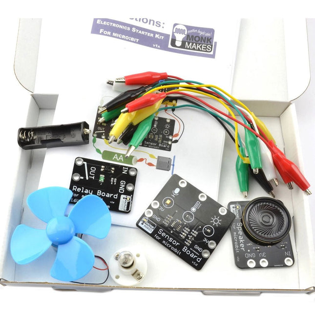
This kit contains everything needed to start learning about connecting electronics to the micro:bit in an accessible and easy manner. Everything is connected using the supplied alligator clips, so no soldering required.
Included
MonkMakes Speaker for micro:bit
MonkMakes Switch for micro:bit
MonkMakes Sensor Board for micro:bit
Set of alligator clip leads (10 leads)
Small motor with fan
Single AA battery box (battery not included)
Light bulb and holder
Booklet (A5)
Downloads
Instructions
Datasheet
Lesson Plans
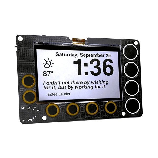
A low-power, open source, 2.7-inch IoT display powered by an ESP32-S2 module and featuring SHARP's Memory-in-Pixel (MiP) screen technology
The Newt is a battery-powered, always-on, wall-mountable display that can go online to retrieve weather, calendars, sports scores, to-do lists, quotes…really anything on the Internet! It is powered by an ESP32-S2 microcontroller that you can program with Arduino, CircuitPython, MicroPython, or ESP-IDF. It's perfect for makers:
Sharp’s Memory-in-Pixel (MiP) technology avoids the slow refresh times associated with E-Ink displays
A real-time clock (RTC) was added to support timers and alarms
The Newt was designed with battery operation in mind; every component on the board was chosen for its ability to operate at low power.
Newt was designed to operate 'untethered,' which means it can be mounted in places where a power cord would be inconvenient, for example a wall, refrigerator, mirror, or dry-erase board. With the optional stand, desks, shelves, and nightstands are also good options.
Newt is open source, and all design files and libraries are available for review, use, and modification. However, doing that is not required. Each Newt is delivered with working code with the following features:
Current weather details
Hourly and daily weather forecast
Alarm
Timer
Inspirational quotes
Air-quality forecast
Habit calendar
Pomodoro timer
Oblique Strategy cards
Only following the Wi-Fi provisioning instructions is needed to get started. No app downloads are required.
Specifications
Display
Sharp Memory LCD
Screen Size
2.7 inch
Resolution
240 x 400
Deep Sleep Current
30 uA
Refresh Rate
< 0.001 s
Periodic Screen Refresh Required
No
Input Buttons
10 capacitive pads, 1 push button
RTC included
Yes
Speaker included
Yes
Power Input
USB Type-C
Battery included
No
Programming Languages
Arduino, CircuitPython, ESP IDF, MicroPython
Dimensions
91 x 61 x 9 mm
Microcontroller
Espressif ESP32-S2-WROVER Module with 4 MB flash and 2 MB PSRAM
Wi-Fi capable
Supports Arduino, MicroPython, CircuitPython, and ESP-IDF
Deep sleep current as low as 25 μA
Display
2.7-inch, 240 x 400 pixel MiP LCD
Capable of delivering high-contrast, high-resolution, low-latency content with ultra-low power consumption
Reflective mode leverages ambient light to eliminate the need for a backlight
Time Keeping, Timers, and Alarms
Micro Crystal RV-3028-C7 RTC
Optimized for extreme low-power consumption (45 μA)
Able to simultaneously manage a periodic timer, a countdown timer, and an alarm
Hardware interrupt for timers and alarms
43 bytes of non-volatile user memory, 2 bytes of user RAM
Separate UNIX time counter
Buzzer
Speaker/buzzer with mini class-D amplifier on DAC output A0 can play tones or lo-fi audio clips
User Input
Power switch
Two programmable tactile buttons for Reset and Boot
10 capacitive touchpads
Power
Newt is designed to operate for one to two months between charges using a 500 mAH LiPo battery. The exact run time varies. (Heavy Wi-Fi use, in particular, will reduce battery charge more quickly.)
USB Type-C connector for programming, power, and charging
Low-quiescence voltage regulator (TOREX XC6220) that can output 1 A of current and operate as low as 8 μA.
JST connector for a Lithium-Ion battery
Battery-charging circuity (MCP73831)
Low-battery indicator (1 μA quiescence current)
Software
Newt hardware is compatible with open-source Arduino libraries for ESP32-S2, Adafruit GFX (fonts), Adafruit Sharp Memory Display (display writing), and RTC RV-3028-C7 (RTC)
Arduino libraries and sample programs are under development and will be available in our GitHub repository before launch
CircuitPython libraries and registration are on the roadmap, with the development of a CircuitPython library for the RV-3028 real-time clock as a key dependency
Included
Phambili Newt – Fully assembled with pre-loaded firmware
Laser-cut desktop stand
Mini-magnet feet
Required screws
Support & Documentation
Full instructions for use
GitHub: Arduino Library and Codebase
GitHub: Board schematics
Videos of prototypes or demos (build tracked on Hackaday)
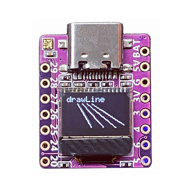
Arduino, MicroPython, and CircuitPython-compatible compact development board powered by Raspberry Pi RP2040
RP2040-0.42LCD is a high-performance development board with integrated 0.42" LCD (70x40 resolution) with flexible digital interfaces.
It incorporates Raspberry Pi's RP2040 microcontroller chip. The RP2040 features a dual-core Arm Cortex-M0+ processor clocked at 133 MHz with 264 KB internal SRAM and 2 MB flash storage.
Specifications
SoC
Raspberry Pi RP2040 dual-core Cortex-M0+ microcontroller at up to 125 MHz, with 264 KB SRAM
Storage
2 MB SPI flash
Display
0.42-inch OLED
USB
1x USB Type-C port for power and programming
Expansion
– Qwiic I²C connector– 7-pin and 8-pin headers with up to 11x GPIOs, 2x SPI, 2x I²C, 4x ADC, 1x UART, 5 V, 3.3 V, VBAT, GND
Misc
– Reset and Boot buttons– RGB LED, power LED
Power supply
– 5 V via USB-C port or Vin– VBAT pin for battery input– 3.3 V regulator with 500 mA peak output
Dimensions
23.5 x 18 mm
Weight
2.5 g
Downloads
GitHub
Maker Line is a line sensor with 5 x IR sensors array that is able to track line from 13 mm to 30 mm width. The sensor calibration is also simplified. There is no need to adjust the potentiometer for each IR sensor. You just have to press the calibrate button for 2 seconds to enter calibration mode. Afterwards you need to sweep the sensors array across the line, press the button again and you are good to go. The calibration data is saved in EEPROM and it will stay intact even if the sensor has been powered off. Thus, calibration only needs to be carried out once unless the sensor height, line color or background color has changed. Maker Line also supports dual outputs: 5 x digital outputs for the state of each sensor independently, which is similar to conventional IR sensor, but you get the benefit of easy calibration, and also one analog output, where its voltage represents the line position. Analog output also offers higher resolution compared to individual digital outputs. This is especially useful when high accuracy is required while building a line following robot with PID control. Features Operating Voltage: DC 3.3 V and 5 V compatible (with reverse polarity protection) Recommended Line Width: 13 mm to 30 mm Selectable line color (light or dark) Sensing Distance (Height): 4 mm to 40 mm (Vcc = 5 V, Black line on white surface) Sensor Refresh Rate: 200 Hz Easy calibration process Dual Output Types: 5 x digital outputs represent each IR sensor state, 1 x analog output represents line position. Support wide range of controllers such as Arduino, Raspberry Pi etc. Documentation Datasheet Tutorial: Building A Low-Cost Line Following Robot
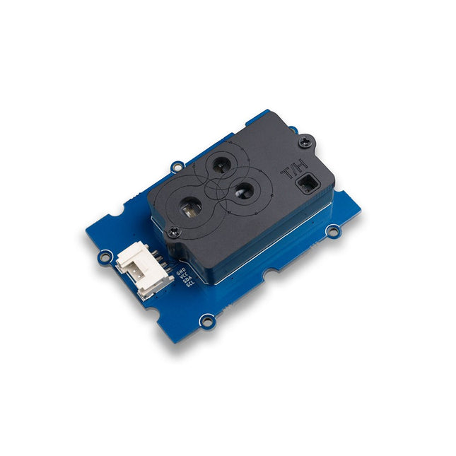
The Grove SCD30 is an Arduino-compatible 3-in-1 environmental sensor for precise CO₂, temperature, and humidity measurements. Powered by the Sensirion SCD30 and advanced Non-Dispersive Infrared (NDIR) technology, it delivers high accuracy across a wide measurement range. The sensor also determines humidity and temperature through smart algorithms that model and compensate for external heat sources.
Features
NDIR CO2 sensor technology: embedded with Sensirion SCD30
Multi-function: Integrates temperature and humidity sensor on the same sensor module
High precision and wide measurement accuracy: ±(30 ppm + 3%) between 400 ppm to 10000 ppm
Superior stability: Dual-channel detection
Easy project operation: Digital interface I²C, Breadboard-friendly, Grove-compatible
Best performance-to-price ratio
Application Ideas
Air Purifier
Environmental Monitoring
Plant Environmental Monitoring system
Arduino weather station
The SparkFun Thing Plus Matter is the first easily accessible board of its kind that combines Matter and SparkFun’s Qwiic ecosystem for agile development and prototyping of Matter-based IoT devices. The MGM240P wireless module from Silicon Labs provides secure connectivity for both 802.15.4 with Mesh communication (Thread) and Bluetooth Low Energy 5.3 protocols. The module comes ready for integration into Silicon Labs' Matter IoT protocol for home automation.
What is Matter? Simply put, Matter allows for consistent operation between smart home devices and IoT platforms without an Internet connection, even from different providers. In doing so, Matter is able to communicate between major IoT ecosystems in order to create a single wireless protocol that is easy, reliable, and secure to use.
The Thing Plus Matter (MGM240P) includes Qwiic and LiPo battery connectors, and multiple GPIO pins capable of complete multiplexing through software. The board also features the MCP73831 single-cell LiPo charger as well as the MAX17048 fuel gauge to charge and monitor a connected battery. Lastly, a µSD card slot for any external memory needs is integrated.
The MGM240P wireless module is built around the EFR32MG24 Wireless SoC with a 32-bit ARM Cortext-M33 core processor running at 39 MHz with 1536 kb Flash memory and 256 kb RAM. The MGM240P works with common 802.15.4 wireless protocols (Matter, ZigBee, and OpenThread) as well as Bluetooth Low Energy 5.3. The MGM240P supports Silicon Labs' Secure Vault for Thread applications.
Specifications
MGM240P Wireless Module
Built around the EFR32MG24 Wireless SoC
32-bit ARM-M33 Core Processor (@ 39 MHz)
1536 kB Flash Memory
256 kB RAM
Supports Multiple 802.15.4 Wireless Protocols (ZigBee and OpenThread)
Bluetooth Low Energy 5.3
Matter-ready
Secure Vault Support
Built-in Antenna
Thing Plus Form-Factor (Feather-compatible):
Dimensions: 5.8 x 2.3 cm (2.30 x 0.9')
2 Mounting Holes:
4-40 screw compatible
21 GPIO PTH Breakouts
All pins have complete multiplexing capability through software
SPI, I²C and UART interfaces mapped by default to labeled pins
13 GPIO (6 labeled as Analog, 7 labeled for GPIO)
All function as either GPIO or Analog
Built-in-Digital to Analog Converter (DAC)
USB-C Connector
2-Pin JST LiPo Battery Connector for a LiPo Battery (not included)
4-Pin JST Qwiic Connector
MC73831 Single-Cell LiPo Charger
Configurable charge rate (500 mA Default, 100 mA Alternate)
MAX17048 Single-Cell LiPo Fuel Gauge
µSD Card Slot
Low Power Consumption (15 µA when MGM240P is in Low Power Mode)
LEDs:
PWR – Red Power LED
CHG – Yellow battery charging status LED
STAT – Blue status LED
Reset Button:
Physical push-button
Reset signal can be tied to A0 to enable use as a peripheral device
Downloads
Schematic
Eagle Files
Board Dimensions
Hookup Guide
Datasheet (MGM240P)
Fritzing Part
Thing+ Comparison Guide
Qwiic Info Page
GitHub Hardware Repo
Learn the basics of electronics by assembling manually your Arduino Uno, become familiar with soldering by mounting every single component, and then unleash your creativity with the only kit that becomes a synth!
The Arduino Make-Your-Uno kit is really the best way to learn how to solder. And when you are done, the packaging allows you to build a synth and make your music.
A kit with all the components to build your very own Arduino Uno and audio synthesizer shield.
The Make-Your-Uno kit comes with a complete set of instructions in a dedicated content platform. This includes video material, a 3D interactive viewer for following detailed instructions, and how to program your board once it is finished.
This kit contains:
Arduino Make-Your-Uno
1x Make-Your-Uno PCB
1x USB C Serial adapter Board
7x Resistors 1k Ohm
2x Resistors 10k Ohm
2x Resistors 1M Ohm
1x Diode (1N4007)
1x 16 MHz Crystal
4x Yellow LEDs
1x Green LED
1x Push-Button
1x MOSFET
1x LDO (3.3 V)
1x LDO (5 V)
3x Ceramic capacitors (22pF)
3x Electrolytic capacitors (47uF)
7x Polyester capacitors (100nF)
1x Socket for ATMega 328p
2x I/O Connectors
1x Connector header 6 pins
1x Barrel jack connector
1x ATmega 328p Microcontroller
Arduino Audio Synth
1x Audio Synth PCB
1x Resistor 100k Ohm
1x Resistor 10 Ohm
1x Audio amplifier (LM386)
1x Ceramic capacitors (47nF)
1x Electrolytic capacitors (47uF)
1x Electrolytic capacitors (220uF)
1x Polyester capacitor (100nF)
4x connectors pin header
6x potentiometer 10k Ohm with plastic knobs
Spare parts
2x Electrolytic capacitors (47uF)
2x Polyester capacitor (100nF)
2x Ceramic capacitors (22pF)
1x Push-Button
1x Yellow LEDs
1x Green LED
Mechanical parts
5x Spacers 12 mm
11x Spacers 6 mm
5x screw nuts
2x screws 12 mm
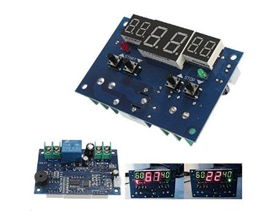
The Intelligent Digital Thermostat Temperature Controller is a small switch controller (77x51mm) which allows you to create your own thermostat. With its NTC Sensor and its LED displays, you are able to switch up to 10A 220V depending on the measured temperature.
Grove 3-Axis Digital Accelerometer (LIS3DHTR) is a low-cost 3-Axis accelerometer in a bundle of Grove products. It is based on the LIS3DHTR chip which provides multiple ranges and interfaces selection. You can never believe that such a tiny 3-Axis accelerometer can support I²C, SPI, and ADC GPIO interfaces, which means you can choose any way to connect with your development board. Besides, this accelerometer can also monitor the surrounding temperature to tune the error caused by it. Features Measurement range: ±2g, ±4g, ±8g, ±16g, multiple ranges selection. Multiple interfaces option: Grove I²C interface, SPI interface, ADC interface. Temperature adjustable: able to adjust and tune the error caused by temperature. 3/5V power supply Specifications Power Supply 3/5V Interfaces IC/SPI/GPIO ADC I²C address Default 0x19, can be changed to 0x18 when connecting SDO Pin with GND ADC GPIO Power input 0-3.3V Interruption An interruption Pin reserved SPI Mode set up Connect the CS Pin with GND Included 1x Grove 3-Axis Digital Accelerometer (LIS3DHTR) 1x Grove cable Downloads LIS3DHTR Datasheet Hardware schematic Arduino Library
Here you will find all kinds of parts, components and accessories you will need in various projects, starting from simple wires, sensors and displays to already pre-assembled modules and kits.