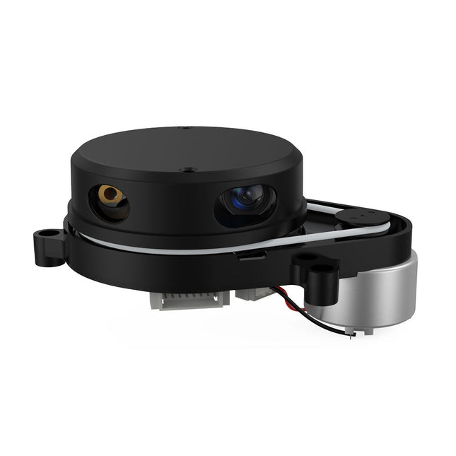
YDLIDAR X4PRO is a 360 degrees two-dimensional rangefinder. Based on the principle of triangulation, it is equipped with related optics, electricity, and algorithm design to achieve high-frequency and high-accuracy distance measurement. The mechanical structure rotates 360 degrees to continuously output the angle information as well as the point cloud data of the scanning environment while ranging.
Features
360 degrees omnidirectional scanning ranging distance measurement
Small distance error, stable performance and high accuracy
Wide ranging distance
Strong resistance to ambient light interference
Low power consumption, small size and long service life
Laser power meets Class I laser safety standards
Adjustable motor speed, scanning frequency is 6~12 Hz
High-speed ranging, ranging frequency up to 5 kHz
Applications
Robot navigation and obstacle avoidance
Robot ROS teaching and research
Regional security
Environmental scanning and 3D reconstruction
Navigation and obstacle avoidance of robot vacuum cleaner/ROS Learning robot
Specifications
Range Frequency
5000 Hz
Scan Frequency
6-12 Hz
Range Distance
0.12-10 m
Scan Angle
360°
Angle Resolution
0.43-0.85°
Dimensions
110.6 x 71.1 x 52.3 mm
Downloads
Datasheet
User Manual
Development Manual
SDK
Tool
ROS
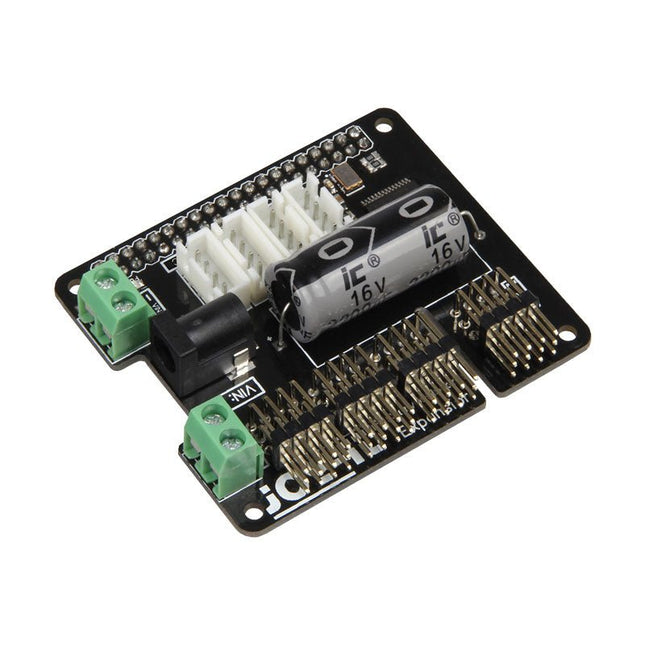
The MotoPi is an extension-board to control and use up to 16 PWM-controlled 5 V servo motors. The board can be additional powered by a voltage between 4.8 V and 6 V so a perfect supply is always guaranteed and even larger projects can be powered.
With the additional power supply and the integrated Analog-Digital-Converter, new possibilities can be reached. An additional power supply per motor is not required anymore because all connections (Voltage, Ground, Control) are directly connected to the board.
The control and the programing can be directly done, as usual, on the Raspberry Pi.
Specifications
Special features
16 Channels, own clock generator, Inkl. Analog Digital Converter
Input 1
Coaxial power connector 5.5 / 2.1 mm, 5 V / 6 A max
Input 2
Screw terminal, 4.8-6 V / 6 A max
Compatible with
Raspberry Pi A+, B+, 2B, 3B
Dimensions
65 x 56 x 24 mm
Scope of supply
Board, manual, fixing material
CrowVision 11.6-inch touch screen is designed for all-in-one machines. It features a 1366 x 768 high-resolution screen and IPS panel, providing a superior visual experience. The industrial design-style rear-fixed metal structure is compatible with various single-board computers (SBCs), with a reasonable layout and neat wiring, making it easy to power up and use with simple operations.
The screen uses HDMI-compatible communication and supports capacitive multi-touch. It has reserved interfaces and buttons for speakers and other accessories, making it adaptable to different usage scenarios. It can be used with a variety of commonly available single-board computers such as Raspberry Pi, Jetson Nano, and is plug-and-play, while also being fully compatible with the operating systems of single-board computers (such as Raspbian, Ubuntu, Windows, Android, Mac OS, and Chrome OS, etc.).
This screen can be widely used in automation application control system displays, personal DIY projects, secondary screen/second window displays, single-board computer audio-video display equipment, HDMI communication devices, game console expansion screens, and other scenarios.
Features
11.6-inch high-resolution screen with 1366 x 768 resolution, IPS panel, and 178° wide viewing angle provides a better visual experience
Unique rear fixing structure with sliding fixing pillars, compatible with most single-board computer models, easy to assemble
Wide compatibility, compatible with multiple operating systems (Raspbian, Ubuntu, Windows, Android, Mac OS, and Chrome OS)
Supports audio, video, and capacitive touch, plug and play
Integrates a variety of peripheral interfaces (such as speakers, headphones, keypads, touchscreens) and onboard OSD adjustment keys
The mainboard is equipped with power conversion function of output 5 V/3 A, not need to separately connect an external power supply for the single-board computer.
Specifications
Display size: 11.6 inch
Touch type: 5-point Capacitive Touch
Resolution: 1366 x 768
Color depth: 16M
Viewing angle: 178° wide viewing angle
Display type: IPS Panel
Screen type: TFT-LCD
External power supply: 12 V/2 A
Digital input: HDMI-compatible interface
Interfaces: 1x Keypad interface, 1x power supply 5 V output, 1x Mini HD interface, 1x touch interface, 1x speaker interface, 1x headphone socket, 1x power supply 12 V input
Compatibility system: Raspbian, Ubuntu, Windows, Android, Mac OS, and Chrome OS, etc.
Active Area: 256.13 x 144 mm
Dimensions: 290.8 x 184.2 mm
Included
1x 11.6-inch capacitive touch ccreen
1x USB-A to USB-C cable
1x USB-A to micro B cable
1x HD to mini HD cable
1x Micro HD to mini HD cable
1x OSD control board
1x Power adapter
1x Screwdriver
2x Ribbon
1x Manual
Downloads
Manual
Wiki
Maker Line is a line sensor with 5 x IR sensors array that is able to track line from 13 mm to 30 mm width.
The sensor calibration is also simplified. There is no need to adjust the potentiometer for each IR sensor. You just have to press the calibrate button for 2 seconds to enter calibration mode. Afterwards you need to sweep the sensors array across the line, press the button again and you are good to go.
The calibration data is saved in EEPROM and it will stay intact even if the sensor has been powered off. Thus, calibration only needs to be carried out once unless the sensor height, line color or background color has changed.
Maker Line also supports dual outputs: 5 x digital outputs for the state of each sensor independently, which is similar to conventional IR sensor, but you get the benefit of easy calibration, and also one analog output, where its voltage represents the line position. Analog output also offers higher resolution compared to individual digital outputs. This is especially useful when high accuracy is required while building a line following robot with PID control.
Features
Operating Voltage: DC 3.3 V and 5 V compatible (with reverse polarity protection)
Recommended Line Width: 13 mm to 30 mm
Selectable line color (light or dark)
Sensing Distance (Height): 4 mm to 40 mm (Vcc = 5 V, Black line on white surface)
Sensor Refresh Rate: 200 Hz
Easy calibration process
Dual Output Types: 5 x digital outputs represent each IR sensor state, 1 x analog output represents line position.
Support wide range of controllers such as Arduino, Raspberry Pi etc.
Downloads
Datasheet
Tutorial: Building A Low-Cost Line Following Robot
Features
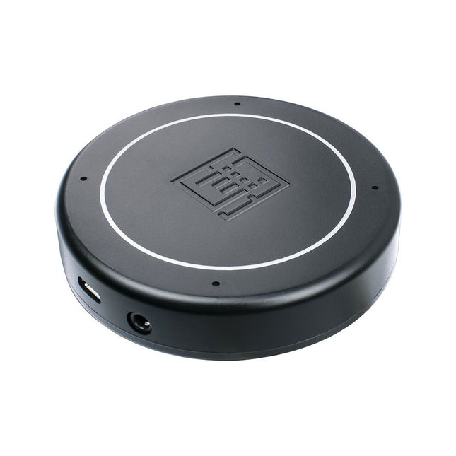
Plug & Play (No driver required), compatible with Windows 10/8/7, Mac, Linux and Android that support OTG.
Voice Pick-up device, Far-field voice pick-up up to 5m and supports 360° pick-up pattern
Acoustic algorithms implemented:
DOA(Direction of Arrival),
AEC(Automatic Echo Cancellation),
AGC(Automatic Gain Control),
NS(Noise Suppression)
Built-in audio jack, which allows for plugging in headphones or speakers (speaker not included)
Applications
Voice pick-up device
Home/Office automation device
In-car voice assistant
Healthcare device
Voice interaction robot
Other applications
Specifications
XVF-3000 from XMOS
4 High-Performance Digital Microphones
Supports Far-field Voice Capture
Speech Algorithms On-Chip
12 Programmable RGB LED Indicators
Microphones: MEMS MSM261D4030H1CPM
Sensitivity: -26 dBFS (Omnidirectional)
Acoustic Overload Point: 120 dB SPL
SNR: 63 dB
Power Supply: 5V DC from Micro USB or Expansion Header
Dimensions: 77mm (Diameter)
3.5mm Audio Jack Output Socket
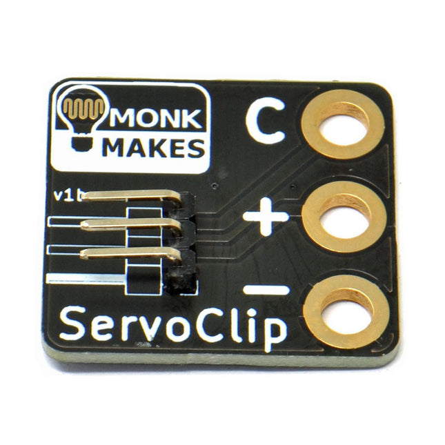
An adapter for connecting a servo meter with croc/alligator clips.
This is a handy little clip to connect a servo motor with 5.4 mm header socket using alligator clips. It is ideal for use with boards like the BBC micro:bit and Adafruit's Circuit Playground Express or Gemma.
Width: 27 mm
Height: 35 mm
Downloads
Datasheet
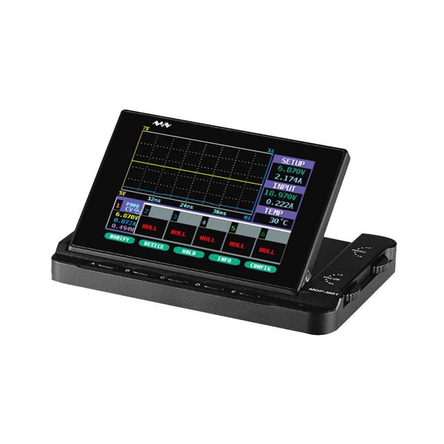
MDP-M01 is a display control module equipped with a 2.8-inch TFT display screen, the screen can be turned 90 degrees, which is convenient for users to view data and waveform. MDP-M01 can realize online display and control with MDP-P906 mini digital power supply modules and other modules of MDP system through 2.4 GHz wireless communication, and can control up to 6 sub-modules at the same time.
Specifications
Screen size
2.8" TFT
Screen resolution
240 x 320
Power
Micro USB power input, or taking power from sub-module via dedicated power cable
Input
DC 5 V/0.3 A
Other functions
Can control up to 6 sub-modulesUpgrade firmware through Micro USB
Dimensions
107 x 66 x 13.6 mm
Weight
133 g
Included
1x MDP-M01 Smart Digital Monitor
1x Cable (2.5 mm jack to Micro USB)
Downloads
User Manual v3.4
Firmware v1.32
Waveshare DVK600 is an FPGA CPLD mother board that features expansion connectors for connecting FPGA CPLD core board and accessory boards. DVK600 provides an easy way to set up FPGA CPLD development system.
Features
FPGA CPLD core board connector: for easily connecting core boards which integrate an FPGA CPLD chip onboard
8I/Os_1 interface, for connecting accessory boards/modules
8I/Os_2 interface, for connecting accessory boards/modules
16I/Os_1 interface, for connecting accessory boards/modules
16I/Os_2 interface, for connecting accessory boards/modules
32I/Os_1 interface, for connecting accessory boards/modules
32I/Os_2 interface, for connecting accessory boards/modules
32I/Os_3 interface, for connecting accessory boards/modules
SDRAM interface
for connecting SDRAM accessory board
also works as FPGA CPLD pins expansion connectors
LCD interface, for connecting LCD22, LCD12864, LCD1602
ONE-WIRE interface: easily connects to ONE-WIRE devices (TO-92 package), such as temperature sensor (DS18B20), electronic registration number (DS2401), etc.
5 V DC jack
Joystick: five positions
Buzzer
Potentiometer: for LCD22 backlight adjustment, or LCD12864, LCD1602 contrast adjustment
Power switch
Buzzer jumper
ONE-WIRE jumper
Joystick jumper
Downloads
Schematics
The Whadda 3D Xmas Tree Kit is aimed at hobbyists and beginners who are interested in soldering and electronics. With this DIY kit, you can build a festive LED Christmas tree.
Features
16 flashing red LEDs
Extra green and yellow LEDs provided to customise your tree
Can be hung on and fed through wires
Will operate on 12 V DC (e.g. in cars)
Specifications
Low power consumption
8 mA
Power supply
9 V battery operation (not included)
Dimensions
102 x 88 x 80 mm
Weight
65 g
Downloads
Manual
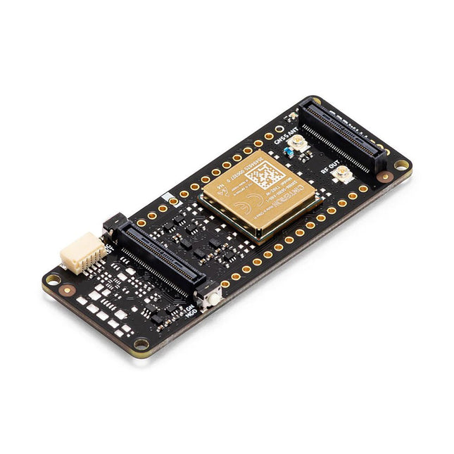
The Arduino Pro Portenta Cat. M1/NB IoT GNSS Shield allows you to enhance the connectivity features of your Portenta H7 applications. The shield leverages a Cinterion TX62 wireless module by Thales, designed for highly efficient, low-power IoT applications to deliver optimized bandwidth and performance.
The Portenta Cat. M1/NB IoT GNSS Shield combines with the strong edge computing power of the Portenta H7 to enable the development of asset tracking and remote monitoring applications in industrial settings, as well as in agriculture, public utilities and smart cities. The shield offers cellular connectivity to both Cat. M1 and NB-IoT networks with the option to use eSIM technology. Easily track your valuables – across the city or worldwide – with your choice of GPS, GLONASS, Galileo or BeiDou.
Features
Change connectivity capabilities without changing the board
Add NB-IoT, CAT. M1 and positioning to any Portenta product
Possibility to create a small multiprotocol router (WiFi - BT + NB-IoT/CAT. M1)
Greatly reduce communication bandwidth requirements in IoT applications
Low-power module
Compatible also with MKR boards
Remote Monitoring
Industrial and agricultural companies can leverage the Portenta Cat. M1/NB IoT GNSS Shield to remotely monitor gas detectors, optical sensors, machinery alarm systems, biological bug traps and more.
Technology providers providing smart city solutions can compound the power and reliability of the Portenta H7 with the Portenta Cat. M1/NB IoT GNSS Shield, to connect data and automate actions for a truly optimized use of resources and enhanced user experience.
Asset Monitoring
Add monitoring capabilities to any asset by combining the performance and edge computing features of the Portenta family boards. The Portenta Cat. M1/NB IoT GNSS Shield is ideal to monitor valuable goods and also for monitoring industrial machinery and equipment.
Specifications
Connectivity
Cinterion TX62 wireless module; NB-IoT - LTE CAT.M1; 3GPP Rel.14 Compliant Protocol LTE Cat. M1/NB1/NB2; UMTS BANDS: 1 / 2 / 3 / 4 / 5 / 8 / 12(17) / 13 / 18 / 19 / 20 / 25 / 26 / 27 / 28 / 66 / 71 / 85; LTE Cat.M1 DL: max. 300 kbps, UL: max. 1.1 Mbps; LTE Cat.NB1 DL: max. 27 kbps, UL: max. 63 kbps; LTE Cat.NB2 DL: max. 124 kbps, UL: max. 158 kbps
Short messaging service (SMS)
Point-to-point mobile terminated (MT) and mobile originated (MO) Text Mode; Protocol Data Unit (PDU) Mode
Localization support
GNSS capability (GPS/BeiDou/Galileo/GLONASS)
Other
Embedded IPv4 and IPv6 TCP/IP stack access; Internet Services: TCP server/client, UDP client, DNS, Ping, HTTP client, FTP client, MQTT client Secure Connection with TLS/DTLS Secure boot
Dimensions
66 x 25.4 mm
Operating temperature
-40° C to +85° C (-104° F to 185°F)
Downloads
Datasheet
Schematics
Here you will find all kinds of parts, components and accessories you will need in various projects, starting from simple wires, sensors and displays to already pre-assembled modules and kits.