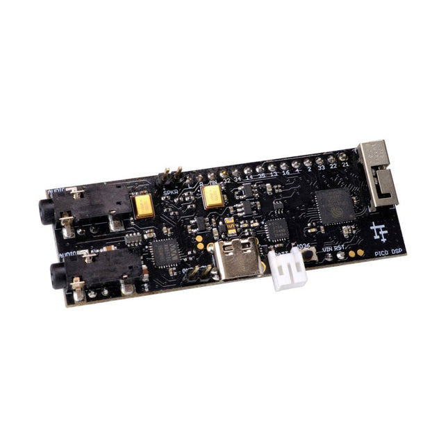
PÚCA DSP is an open-source, Arduino-compatible ESP32 development board for audio and digital signal processing (DSP) applications with expansive audio-processing features. It provides audio inputs, audio outputs, a low-noise microphone array, an integrated test-speaker option, additional memory, battery-charge management, and ESD protection all on a small, breadboard-friendly PCB.
Synthesizers, Installations, Voice UI, and More
PÚCA DSP can be used for a wide range of DSP applications, including but not limited to those in the fields of music, art, creative technology, and adaptive technology. Music-related examples include digital-music synthesis, mobile recording, Bluetooth speakers, wireless line-level directional microphones, and the design of smart musical instruments. Art-related examples include acoustic sensor networks, sound-art installations, and Internet-radio applications. Examples related to creative and adaptive technology include voice user interface (VUI) design and Web audio for the Internet of Sounds.
Compact, Integrated Design
PÚCA DSP was designed for portability. When used with an external 3.7 V rechargeable battery, it can be deployed almost anywhere or integrated into just about any device, instrument, or installation. Its design emerged from months of experimentation with various ESP32 development boards, DAC breakout boards, ADC breakout boards, Microphone breakout boards, and audio-connector breakout boards, and – despite its diminutive size – it manages to provide all of that functionality in a single board. And it dos so without compromising signal quality.
Specifications
Processor & Memory
Espressif ESP32 Pico D4 Processor
32-bit dual core 80 MHz / 160 MHz / 240 MHz
4 MB SPI Flash with 8 MB additional PSRAM (Original Edition)
Wireless 2.4 GHz Wi-Fi 802.11b/g/n
Bluetooth BLE 4.2
3D Antenna
Audio
Wolfson WM8978 Stereo Audio Codec
Audio Line In on 3.5 mm stereo onnector
Audio Headphone / Line Out on 3.5 mm stereo connector
Stereo Aux Line In, Audio Mono Out routed to GPIO Header
2x Knowles SPM0687LR5H-1 MEMS Microphones
ESD protection on all audio inputs and outputs
Support for 8, 11.025, 12, 16, 22.05, 24, 32, 44.1 and 48 kHz sample rates
1 W Speaker Driver, routed to GPIO Header
DAC SNR 98 dB, THD -84 dB (‘A’ weighted @ 48 kHz)
ADC SNR 95 dB, THD -84 dB (‘A’ weighted @ 48 kHz)
Line input impedance: 1 MOhm
Line output impedance: 33 Ohm
Form Factor and Connectivity
Breadboard friendly
70 x 24 mm
11x GPIO pins broken out to 2.54 mm pitch header, with access to both ESP32 ADC channels, JTAG and capacitive touch pins
USB 2.0 over USB Type C connector
Power
3.7/4.2 V Lithium Polymer Rechargeable Battery, USB or external 5 V DC power source
ESP32 and Audio Codec can be placed into low power modes under software control
Battery voltage level detection
ESD protection on USB data bus
Downloads
GitHub
Datasheet
Links
Crowd Supply Campaign (includes FAQs)
Hardware Overview
Programming the Board
The Audio Codec
The full-color, spiral-bound SIK guidebook (included) contains step-by-step instructions with circuit diagrams and hookup tables for building each project and circuit with the included parts. Full example code is provided, new concepts and components are explained at the point of use, and troubleshooting tips offer assistance if something goes wrong.
The kit does not require any soldering and is recommended for beginners ages 10 and up looking for an Arduino starter kit. For SIK version 4.1, Sparkfun took an entirely different approach to teaching embedded electronics. In previous versions of the SIK, each circuit focused on introducing a new piece of technology. With SIK v4.1, components are introduced in the context of the circuit you are building. Each circuit builds upon the last, leading up to a project that incorporates all of the components and concepts introduced throughout the guide. With new parts and a completely new strategy, even if you've used the SIK before, you're in for a brand-new experience!
The SIK V4.1 includes the Redboard Qwiic, which allows you to expand into the SparkFun Qwiic ecosystem after becoming proficient with the SIK circuits. The SparkFun Qwiic Connect System is an ecosystem of I²C sensors, actuators, shields and cables that make prototyping faster and less prone to error. All Qwiic-enabled boards use a common 1mm pitch, 4-pin JST connector. This reduces the amount of required PCB space, and polarized connections mean you can’t hook it up wrong. With the addition of the SparkFun RedBoard Qwiic, you will need to download a new driver install that is different from the original SparkFun RedBoard.
Included
SparkFun RedBoard Qwiic
Arduino and Breadboard Holder
SparkFun Inventor's Kit Guidebook
White Solderless Breadboard
Carrying Case
SparkFun Mini Screwdriver
16 x 2 White-on-Black LCD (with headers)
SparkFun Motor Driver (with Headers)
Pair of Rubber Wheels
Pair of Hobby Gearmotors
Small Servo
Ultrasonic Distance Sensor
TMP36 Temp Sensor
6' USB Micro-B Cable
Jumper Wires
Photocell
Tricolour LED
Red, Blue, Yellow and Green LEDs
Red, Blue, Yellow and Green Tactile Buttons
10K Trimpot
Mini Power Switch
Piezo Speaker
AA Battery Holder
330 and 10K Resistors
Binder Clip
Dual-Lock Fastener
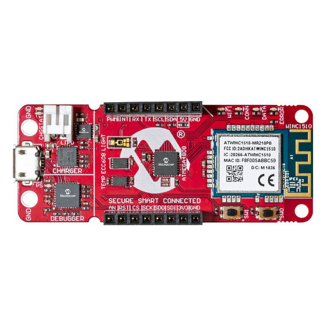
The AVR-IoT WA development board combines a powerful ATmega4808 AVR MCU, an ATECC608A CryptoAuthentication secure element IC and the fully certified ATWINC1510 Wi-Fi network controller – which provides the most simple and effective way to connect your embedded application to Amazon Web Services (AWS). The board also includes an on-board debugger, and requires no external hardware to program and debug the MCU.
Out of the box, the MCU comes preloaded with a firmware image that enables you to quickly connect and send data to the AWS platform using the on-board temperature and light sensors. Once you are ready to build your own custom design, you can easily generate code using the free software libraries in Atmel START or MPLAB Code Configurator (MCC).
The AVR-IoT WA board is supported by two award-winning Integrated Development Environments (IDEs) – Atmel Studio and Microchip MPLAB X IDE – giving you the freedom to innovate with your environment of choice.
Features
ATmega4808 microcontroller
Four user LED’s
Two mechanical buttons
mikroBUS header footprint
TEMT6000 Light sensor
MCP9808 Temperature sensor
ATECC608A CryptoAuthentication™ device
WINC1510 WiFi Module
On-board Debugger
Auto-ID for board identification in Atmel Studio and Microchip MPLAB X
One green board power and status LED
Programming and debugging
Virtual COM port (CDC)
Two DGI GPIO lines
USB and battery powered
Integrated Li-Ion/LiPo battery charger
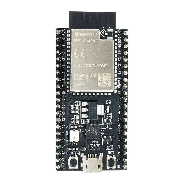
ESP32-S2-Saola-1R is a small-sized ESP32-S2 based development board. Most of the I/O pins are broken out to the pin headers on both sides for easy interfacing. Developers can either connect peripherals with jumper wires or mount ESP32-S2-Saola-1R on a breadboard.ESP32-S2-Saola-1R is equipped with the ESP32-S2-WROVER module, a powerful, generic Wi-Fi MCU module that has a rich set of peripherals. It is an ideal choice for a wide variety of application scenarios relating to Internet of Things (IoT), wearable electronics and smart home. The board a PCB antenna and features a 4 MB external SPI flash and an additional 2 MB SPI Pseudo static RAM (PSRAM).FeaturesMCU
ESP32-S2 embedded, Xtensa® single-core 32-bit LX7 microprocessor, up to 240 MHz
128 KB ROM
320 KB SRAM
16 KB SRAM in RTC
WiFi
802.11 b/g/n
Bit rate: 802.11n up to 150 Mbps
A-MPDU and A-MSDU aggregation
0.4 µs guard interval support
Center frequency range of operating channel: 2412 ~ 2484 MHz
Hardware
Interfaces: GPIO, SPI, LCD, UART, I²C, I²S, Camera interface, IR, pulse counter, LED PWM, TWAI (compatible with ISO 11898-1), USB OTG 1.1, ADC, DAC, touch sensor, temperature sensor
40 MHz crystal oscillator
4 MB SPI flash
Operating voltage/Power supply: 3.0 ~ 3.6 V
Operating temperature range: –40 ~ 85 °C
Dimensions: 18 × 31 × 3.3 mm
Applications
Generic Low-power IoT Sensor Hub
Generic Low-power IoT Data Loggers
Cameras for Video Streaming
Over-the-top (OTT) Devices
USB Devices
Speech Recognition
Image Recognition
Mesh Network
Home Automation
Smart Home Control Panel
Smart Building
Industrial Automation
Smart Agriculture
Audio Applications
Health Care Applications
Wi-Fi-enabled Toys
Wearable Electronics
Retail & Catering Applications
Smart POS Machines
The SparkFun RedBoard Qwiic is an Arduino-compatible board that combines features of different Arduinos with the Qwiic Connect System.
Features
ATmega328 microcontroller with Optiboot Bootloader
R3 Shield Compatible
CH340C Serial-USB Converter
3.3 V to 5 V Voltage Level Jumper
A4 / A5 Jumpers
AP2112 Voltage Regulator
ISP Header
Input voltage: 7 V - 15 V
1 Qwiic Connector
16 MHz Clock Speed
32 k Flash Memory
All SMD Construction
Improved Reset Button
A modern USB-C connector makes programming easy. In addition to the pins broken out, two separate Qwiic-enabled I²C ports allow you to easily daisy chain Qwiic-enabled devices. We've exposed the SWD pins for more advanced users who prefer to use professional tools' power and speed. A USB-A connector is provided for Processor Boards that have USB Host support. A backup battery is provided for processor boards with RTC. If you need a 'lot' of GPIO with a simple-to-program, ready for the market module, the ATP is the fix you need. We've even added a convenient jumper to measure the current consumption for low power testing. Features M.2 Connector Operating Voltage Range ~3.3 V to 6.0 V (via VIN to AP7361C 3.3V Voltage Regulator) 3.3 V (via 3V3) Ports 1x USB type C 1x USB type A Host 2x Qwiic Enabled I²C 1x CAN 1x I²S 2x SPI 2x UARTs 2x Dedicated Analog Pins 2x Dedicated PWM Pins 2x Dedicated Digital Pins 12x General Purpose Input Output Pins 1x SWD 2x5 header 1 mAh battery backup for RTC Buttons Reset Boot LEDs Power 3.3 V Phillips #0 M2.5x3mm screw included
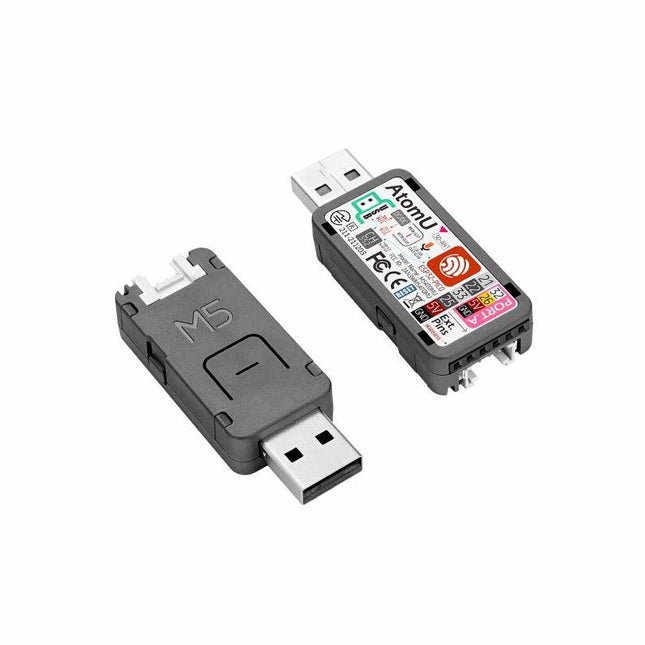
ATOM U is a compact low-power consumption speech recognition IoT development kit. It adopts an ESP32 chipset, equipped with 2 low-power Xtensa 32-bit LX6 microprocessors with the main frequency of up to 240 MHz. Built-in USB-A interface, IR emitter, programmable RGB LED. Plug-and-play, easy to upload and download programs. Integrated Wi-Fi and digital microphone SPM1423 (I2S) for the clear sound record. suitable for HMI, Speech-to-Text (STT). Low-code development ATOM U supports UIFlow graphical programming platform, scripting-free, cloud push; Fully compatible with Arduino, MicroPython, ESP32-IDF, and other mainstream development platforms, to quickly build various applications. High integration ATOM U contains a USB-A port for programming/power supply, IR emitter, programmable RGB LED x1, button x1; Finely tuned RF circuit, providing stable and reliable wireless communication. Strong expandability ATOM U is easy access to M5Stack's hardware and software system. Features ESP32-PICO-D4 (2.4GHz Wi-Fi dual mode) Integrated programmable RGB LED and button Compact design Built-in IR emitter Expandable pinout and GROVE port Development platform: UIFlow MicroPython Arduino Specifications ESP32-PICO-D4 240MHz dual core, 600 DMIPS, 520KB SRAM, 2.4G Wi-Fi Microphone SPM1423 Microphone sensitivity 94 dB SPL@1 KHz Typical value: -22 dBFS Microphone signal-to-noise ratio 94 dB SPL@1 KHz, A-weighted Typical value: 61.4 dB Standby working current 40.4 mA Support input sound frequency 100 Hz ~ 10 KHz Support PDM clock frequency 1.0 ~ 3.25 MHz Weight 8.4 g Product size 52 x 20 x 10 mm Downloads Documentation
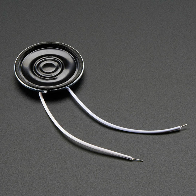
Specifications Datasheet Resonance Frequency (FO): 680 ±20% Hz at 1 V Rated Impedance: 8 ±20% Ω (at 1 KHz) Frequency Range: ~600-10 KHz Rated Input Power: 0.25 W Max Input Power: 0.5 W Temperature Range: -20ºC ~ 55ºC Dimensions Diameter: 28 mm / 1.1' Height: 4.5 mm Weight: 6 g
The Data Logging Carrier Board breaks out connections for I²C via a Qwiic connector or standard 0.1'-spaced PTH pins along with SPI and serial UART connections for logging data from peripheral devices using those communication protocols.
The Data Logging Carrier Board allows you to control power to both the Qwiic connector on the board and a dedicated 3.3 V power rail for non-Qwiic peripherals so you can pick and choose when to power the peripherals you are monitoring the data from. It also features a charging circuit for single-cell Lithium-ion batteries along with a separate RTC battery-backup circuit to maintain power to a real-time clock circuit on your Processor Board.
Features
M.2 MicroMod Connector
microSD socket
USB-C Connector
3.3 V 1 A Voltage Regulator
Qwiic Connector
Boot/Reset Buttons
RTC Backup Battery & Charge Circuit
Independent 3.3 V regulators for Qwiic bus and peripheral add-ons
Controlled by digital pins on Processor Board to enable low power sleep modes
Phillips #0 M2.5 x 3 mm screw included
Add colors to your projects with this collection of red, green, yellow, blue and white LEDs. They come with various current limiting resistors in order to protect the parts and control the brightness.Included
10 mm LEDs
1x red
1x green
1x yellow
1x blue
1x white
5 mm LEDs
5x red
5x green
5x yellow
5x blue
5x white
3 mm LEDs
5x red
5x green
5x yellow
5x blue
5x white
25x 330 Ω resistors
10x 1 kΩ resistors
10x 10 kΩ resistors
10x 100 kΩ resistors
10x 1 MΩ resistors
The SparkFun Qwiic OpenLog is the smarter and better looking cousin to the extremely popular OpenLog but now we've ported the original serial based interface to I²C! Thanks to the added Qwiic connectors, you can daisy chain multiple I²C devices and log them all without taking up your serial port. The Qwiic OpenLog can store, or 'log', huge amounts of serial data and act as a black box of sorts to store all the data that your project generates, for scientific or debugging purposes. Utilizing our handy Qwiic system, no soldering is required to connect it to the rest of your system. However, we still have broken out 0.1'-spaced pins in case you prefer to use a breadboard. Like its predecessor, the SparkFun Qwiic OpenLog runs off of an onboard ATmega328, running at 16 MHz thanks to the onboard resonator. The ATmega328 has been sure to feature the Optiboot bootloader loaded, which allows the OpenLog to be compatible with the “Arduino Uno” board setting in the Arduino IDE. It is important to be aware that the Qwiic OpenLog draws approximately 2 mA-6 mA in idle (nothing to record) mode, however, during a full record the OpenLog can draw 20 mA to 23 mA depending on the microSD card being used. The Qwiic OpenLog also supports clock stretching, which means it performs even better than the original and will record data up to 20,000 bytes per second at 400 kHz. As the receive buffer fills up this OpenLog will hold the clock line, letting the master know that it is busy. Once the Qwiic OpenLog is finished with a task, it releases the clock thus allowing the data to continue flowing without corruption. For even better performance the OpenLog Artemis is the tool you need, featuring logging speeds up to 500000 bps. Features Continuous data logging at 20,000 bytes per second without corruption Compatible with high speed 400 kHz I²C Compatible with 64 MB to 32 GB microSD cards (FAT16 or FAT32) Preloaded Uno bootloader so upgrading the firmware is as easy as loading a new sketch Valid I²C Addresses: 0x08 to 0x77 2x Qwiic Connectors Downloads Schematic Eagle Files Hookup Guide Arduino Library GitHub
The M5Stack Core Ink Development Kit is a new E-Ink display that uses an ESP32-Pico-D4 to take advantage of the benefits of the E-Ink technology.
E-Ink displays are easier on the eyes, have extremely low power consumption and can retain an image even after they have run out of power.
Features
ESP32 Standard wireless functions WiFi, Bluetooth
Internal 4M Flash
Low Power Display
180-degree viewing angle
Expansion ports
Built-in Magnet
Internal Battery
Multi-function button
Status LED
Buzzer
Deep Sleep functionality
Applications
IoT Terminal
E-Book
Industrial Control Panel
Electronic Tag
Included
1x CoreInk
1x LiPo 390 mAh
1x Type-C USB(20cm)
Please note: avoid long-time high-frequency refresh when using it. The recommended refresh interval is (15s/time). Do not expose to ultraviolet rays for a long time, otherwise, it may cause irreversible damage to the ink screen.
This module includes an integrated trace antenna, fits the IC to an FCC-approved footprint, and includes decoupling and timing mechanisms that would need to be designed into a circuit using the bare nRF52840 IC. The Bluetooth transceiver included on the nRF52840 boasts a BT 5.1 stack. It supports Bluetooth 5, Bluetooth mesh, IEEE 802.15.4 (Zigbee & Thread) and 2.4Ghz RF wireless protocols (including Nordic's proprietary RF protocol) allowing you to pick which option works best for your application.
Features
ARM Cortex-M4 CPU with a floating-point unit (FPU)
1MB internal Flash -- For all of your program, SoftDevice, and file-storage needs!
256kB internal RAM -- For your stack and heap storage.
Integrated 2.4GHz radio with support for:
Bluetooth Low Energy (BLE) -- With peripheral and/or central BLE device support
Bluetooth 5 -- Mesh Bluetooth!
ANT -- If you want to turn the device into a heart-rate or exercise monitor.
Nordic's proprietary RF protocol -- If you want to communicate, securely, with other Nordic devices.
Every I/O peripheral you could need.
USB -- Turn your nRF52840 into a USB mass-storage device, use a CDC (USB serial) interface, and more.
UART -- Serial interfaces with support for hardware flow-control if desired.
I²C -- Everyone's favourite 2-wire bi-directional bus interface
SPI -- If you prefer the 3+-wire serial interface
Analogue-to-digital converters (ADC) -- Eight pins on the nRF52840 Mini Breakout support analogue inputs
PWM -- Timer support on any pin means PWM support for driving LEDs or servo motors.
Real-time clock (RTC) -- Keep close track of seconds and milliseconds, also supports timed deep-sleep features.
Three UARTs
Primary tied to USB interface. Two hardware UARTs.
Two I²C Buses
Two SPI Buses
Secondary SPI Bus primarily used for Flash IC.
PDM Audio Processing
Two Analog Inputs
Two Dedicated Digital I/O Pins
Two Dedicated PWM Pins
Eleven General Purpose I/O Pins
The Grove DHT11 Temperature & Humidity Sensor is a high-quality, low-cost digital temperature, and humidity sensor based on the DHT11 module. It is the most common temperature and humidity module for Arduino and Raspberry Pi. It is widely favored by hardware enthusiasts for its many advantages such as low power consumption and excellent long-term stability. Relatively high measurement accuracy can be obtained at a very low cost. The single-bus digital signal is output through the built-in ADC, which saves the I/O resources of the control board. Features Dimensions: 40 x 20 x 8 mm Weight: 10 g Battery: Exclude Input Voltage: 3.3 V & 5 V Measuring Current: 1.3 mA- 2.1 mA Measuring Humidity Range: 5% - 95% RH Measuring Temperature Range: -20 ℃ - 60 ℃
Voice recognition, always-on voice commands, gesture, or image recognition are possible with TensorFlow applications. The cloud is impressively robust, but all-the-time connection requires power and connectivity that may not be available. Edge computing handles discrete tasks such as determining if someone said 'yes' and responds accordingly. The audio analysis is done on the MicroMod combination rather than on the web. This dramatically reduces costs and complexity while limiting potential data privacy leaks.
This board features two MEMS microphones (one with a PDM interface, one with an I²S interface), an ST LIS2DH12 3-axis accelerometer, a connector to interface to a camera (sold separately), and a Qwiic connector. A modern USB-C connector makes programming easy and we've exposed the JTAG connector for more advanced users who prefer to use the power and speed of professional tools. We've even added a convenient jumper to measure current consumption for low power testing.
Features
M.2 MicroMod Keyed-E H4.2mm 65 pins SMD Connector 0.5mm
Digital I²C MEMS Microphone PDM Invensense ICS-43434 (COMP)
Digital PDM MEMS Microphone PDM Knowles SPH0641LM4H-1 (IC)
ML414H-IV01E Lithium Battery for RTC
ST LIS2DH12TR Accelerometer (3-axis, ultra-low-power)
24 Pin 0.5mm FPC Connector (Himax camera connector)
USB-C
Qwiic connector
MicroSD socket
Phillips #0 M2.5x3mm screw included
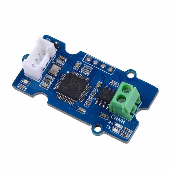
This Grove CAN-BUS Module based on GD32E103 adopts a brand-new design, uses the cost-effective and high-performance GD32E103 microcontroller as the main control and cooperates with a firmware we wrote to complete the function of the serial port to CAN FD. Features
Support CAN communication: Implements CAN FD at up to 5 Mb/s
Easy to program: Support AT command which enables simple serial port programming
Grove ecosystem: 20 x 40 x 10 mm small size, 4-pin Grove connector to plug and play, Arduino compatible This Grove CAN-BUS Module supports CAN FD(CAN with Flexible Data-Rate) communication, which is an extension to the original CAN protocol as specified in ISO 11898-1 that responds to increased bandwidth requirements in automotive networks. In CAN FD, the data rate (i.e. number of bits transmitted per second) is increased to be 5 times faster than the classic CAN (5 Mbit/s for the data payload only, the arbitration bit rate is still limited to 1Mbit/s for compatibility). It supports AT command which enables simple serial port programming. This Grove CAN-BUS Module is based on GD32E103 with a frequency up to 120 MHz. It has a flash size from 64 KB to 128 KB and an SRAM size from 20 KB to 32 KB. Applications Car hacking: allows different parts of the vehicle to talk to each other, including the engine, the transmission, and the brakes. Windows, doors, and mirror adjustment. 3D Printers Building automation Lighting control systems Medical instruments and equipment Specifications MCU GD32E103 UART baud rate Up to 115200 (default 9600) CAN FD baud rate Up to 5 Mb/s Indicator TX and RX led Working voltage 3.3 V Grove connector 4-pin Grove connector to plug and play Size 20 x 40 x 10 mm Downloads Datasheet GitHub
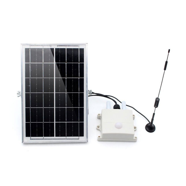
This air monitor is specifically used for monitoring greenhouses. It detects:
Air temperature & Humidity
CO2 concentration
Light intensity
Then transmit the data via LoRa P2P to the LoRa receiver (on your desk in the room) so that the user can monitor the field status or have it recorded for long-term analysis.
This module monitors the greenhouse field status and sends all sensor data regularly via LoRa P2P in Jason format. This LoRa signal can be received by the Makerfabs LoRa receiver and thus displayed/recorded/analyzed on the PC. The monitoring name/data cycle can be set with a phone, so it can be easily implemented into the file.
This air monitor is powered by an internal LiPo battery charged by a solar panel and can be used for at least 1 year with the default setting (cycle 1 hour).
Features
ESP32S3 module onboard with the WiFi and Bluetooth
Ready to use: Power it on directly to use
Module name/signal interval settable easily by phone
IP68 water-proof
Temperature: -40°C~80°C, ±0.3
Humidity: 0~100% moisture
CO2: 0~1000 ppm
Light intensity: 1-65535 lx
Communication distance: Lora: >3 km
1000 mAh battery, charger IC onboard
Solar panel 6 W, ensure system works
Downloads
Manual
BH1750 Datasheet
SGP30 Datasheet
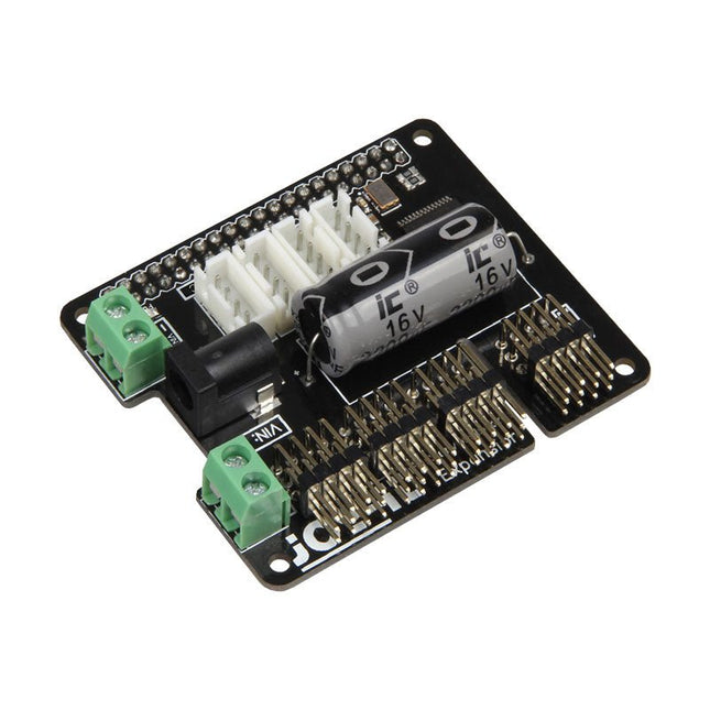
The MotoPi is an extension-board to control and use up to 16 PWM-controlled 5 V servo motors. The board can be additional powered by a voltage between 4.8 V and 6 V so a perfect supply is always guaranteed and even larger projects can be powered. With the additional power supply and the integrated Analog-Digital-Converter, new possibilities can be reached. An additional power supply per motor is not required anymore because all connections (Voltage, Ground, Control) are directly connected to the board. The control and the programing can be directly done, as usual, on the Raspberry Pi. Special features 16 Channels, own clock generator, Inkl. Analog Digital Converter Input 1 Coaxial power connector 5.5 / 2.1 mm, 5 V / 6 A max Input 2 Screw terminal, 4.8-6 V / 6 A max Compatible with Raspberry Pi A+, B+, 2B, 3B Dimensions 65 x 56 x 24 mm Scope of supply Board, manual, fixing material
The OKdo E1 is an ultra-low-cost Development Board based on the NXP LPC55S69JBD100 dual-core Arm Cortex-M33 microcontroller. The E1 board is perfect for Industrial IoT, building control and automation, consumer electronics, general embedded and secure applications.
Features
Processor with Arm TrustZone, Floating Point Unit (FPU) and Memory Protection Unit (MPU)
CASPER Crypto co-processor to enable hardware acceleration for certain asymmetric cryptographic algorithms
PowerQuad Hardware Accelerator for fixed and floating point DSP functions
SRAM Physical Unclonable Function (PUF) for key generation, storage and reconstruction
PRINCE module for real-time encryption and decryption of flash data
AES-256 and SHA2 engines
Up to Nine Flexcomm interfaces. Each Flexcomm interface can be selected by software to be a USART, SPI, I²C, and I²S interface
USB 2.0 High-Speed Host/Device controller with on-chip PHY
USB 2.0 Full-Speed Host/Device controller with on-chip PHY
Up to 64 GPIOs
Secure digital input/output (SD/MMC and SDIO) card interface
Specifications
LPC55S69JBD100 640kbyte flash microcontroller
In-built CMSIS-DAP v1.0.7 debugger based on LPC11U35
Internal PLL support up to 100MHz operation, 16MHz can be mounted for full 150MHz operation.
SRAM 320kB
32kHz crystal for real-time clock
4 user switches
3-colour LED
User USB connector
2-off 16-way expansion connectors
UART over USB virtual COM port
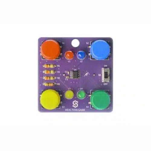
If you are looking for a simple way to learn soldering, or just want to make a small gadget that you can carry, this set is a great opportunity. Reaction game is an educational kit which teaches you how to solder, and in the end, you get to have your own small game. The goal of the game is to press the button next to the LED as soon as it turns on. With every correct answer, the game gets a bit harder – the time you have to press the button shortens. How many correct answers can you get?
It’s based on ATtiny404 microcontroller, programmed in Arduino. At its back, you’ll find CR2032 battery which makes the kit portable. There’s keychain holder as well. Soldering process is easy enough based on the mark on the PCB.
Included
1x PCB
1x ATtiny404 microcontroller
4x LEDs
4x Pushbuttons
1x Switch
4x Resistors (330 ohm)
1x CR2032 battery holder
1x Battery CR2032
1x Keychain holder
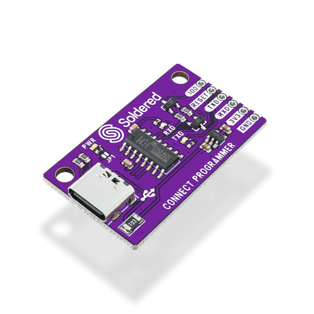
The Soldered CONNECT Programmer is designed to make programming boards based on ESP8266 and ESP32 microcontrollers extremely simple. It contains all the necessary electronics and logic, allowing programming to be done by simply plugging a USB cable into the CONNECT Programmer and connecting it to the programming header. The onboard circuitry handles timing and signal sequencing automatically, placing the ESP microcontroller into bootloader mode without the need for manual intervention.
Features
IC: CH340
Pin layout: GPIO0, RESET, RX, TX, 3V3, GND
LEDs: RX, TX, power
Interface: USB-C
Dimensions: 38 x 22 mm
Downloads
Datasheet
GitHub
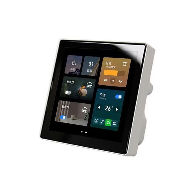
Take control of your smart environment with the compact and powerful 4-inch ESP32-S3 IPS Touchscreen Control Panel. Designed for high performance and versatility, this sleek 86-box format panel integrates advanced connectivity, intuitive touch control, and real-time environmental sensing.
Features
Powerful Core Module WT32-S3-WROVER-N16R8
4-inch IPS full-screen display
Resolution: 480 x 480 pixels (RGB565 format)
Screen Driver IC: GC9503V
Touch Controller IC: FT6336U
Equipped with an SHT20 Temperature and Humidity Sensor for real-time monitoring of environmental conditions.
RS485 Interface using an automatic transceiver circuit
Built-in WiFi and Bluetooth
Applications
Smart Home Control Panels
Industrial Automation Interfaces
Environmental Monitoring Systems
IoT Projects and Custom Smart Solutions
Pico Cube is a 4x4x4 LED cube HAT for Raspberry Pi Pico with 5 VDC operating voltage. Pico cube, a monochromatic Green with 64 LEDs, is a fun way to learn programming. It is designed to perform incandescent operations with low energy consumptions, robust outlook, and easy installation that make people/kids/users learn the effects of LED lights with a different pattern of colors via the combination of software and hardware i.e. Raspberry Pi Pico.
Features
Standard 40 Pins Raspberry Pi Pico Header
GPIO Based Communication
64 High-Intensity Monochromatic LEDs
Individual LED access
Each Layer Access
Specifications
Operating Voltage: 5 V
Color: Green
Communication: GPIO
LEDs: 64
Included
1x Pico Cube Base PCB
4x Layer PCB
8x Pillar PCB
2x Male Berg (1 x 20)
2x Female Berg (1 x 20)
70 LEDs
Note: Raspberry Pi Pico is not included.
Downloads
GitHub
Wiki
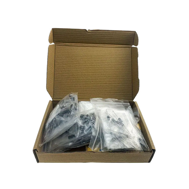
Here you will find all kinds of parts, components and accessories you will need in various projects, starting from simple wires, sensors and displays to already pre-assembled modules and kits.