Bestsellers
-
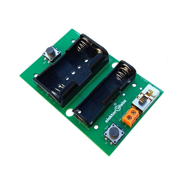
Elektor Labs Elektor Milliohmmeter Adapter
The Elektor Milliohmmeter Adapter uses the precision of a multimeter to measure very low resistance values. It is an adapter that converts a resistance into a voltage that can be measured with a standard multimeter. The Elektor Milliohmmeter Adapter can measure resistances below 1 mΩ using a 4-wire (Kelvin) method. It is useful for locating short circuits on printed circuit boards (PCB). The adapter features three measurement ranges – 1 mΩ, 10 mΩ, and 100 mΩ – selectable via a slide switch. It also includes onboard calibration resistors. The Elektor Milliohmmeter Adapter is powered by three 1.5 V AA batteries (not included). Specifications Measurement ranges 1 mΩ, 10 mΩ, 100 mΩ, 0.1% Power supply 3x 1.5 V AA batteries (not included) Dimensions 103 x 66 x 18 mm (compatible with Hammond 1593N-type enclosure, not included) Special feature On-board calibration resistors Downloads Documentation
€ 34,95
Members: € 31,46
-
Elektor Digital The Arduino-Inside Measurement Lab (E-book)
An 8-in-1 test & measurement instrument for the electronics workbench A well-equipped electronics lab is crammed with power supplies, measuring devices, test equipment and signal generators. Wouldn‘t it be better to have one compact device for almost all tasks? Based on the Arduino, a PC interface is to be developed that’s as versatile as possible for measurement and control. It simply hangs on a USB cable and – depending on the software – forms the measuring head of a digital voltmeter or PC oscilloscope, a signal generator, an adjustable voltage source, a frequency counter, an ohmmeter, a capacitance meter, a characteristic curve recorder, and much more. The circuits and methods collected here are not only relevant for exactly these tasks in the "MSR" electronics lab, but many details can also be used within completely different contexts.
€ 29,95
Members: € 26,96
-

Elektor Publishing Vintage Radio Equipment
Resonances From Aether Days A Pictorial and Technical Analysis from WWII to the Internet Age From the birth of radio to the late 1980s, much of real life unfolded through shortwave communication. World War II demonstrated—beyond a shadow of a doubt—that effective communications equipment was a vital prerequisite for military success. In the postwar years, shortwave became the backbone on which many of the world's most critical services depended every day. All the radio equipment—through whose cathodes, grids, plates, and transistors so much of human history has flowed—is an exceptional subject of study and enjoyment for those of us who are passionate about vintage electronics. In this book, which begins in the aftermath of World War II, you’ll find a rich collection of information: descriptions, tips, technical notes, photos, and schematics that will be valuable for anyone interested in restoring—or simply learning about—these extraordinary witnesses to one of the most remarkable eras in technological history. My hope is that these pages will help preserve this vast treasure of knowledge, innovation, and history—a heritage that far transcends the purely technical.
€ 79,95
Members: € 71,96
-

Elektor Publishing Practical Microcontroller Cryptography
From Simple Ciphers to Secure Systems Understanding how to apply cryptography on modern microcontrollers is essential for building secure, reliable, and trustworthy systems. This book explains cryptography in the context of embedded hardware, from classical ciphers that illustrate core principles to modern techniques such as AES for practical high-security applications. By combining mathematical theory with real-world microcontroller implementations, readers learn not only how cryptography works, but also how to implement it effectively on systems with limited processing power and memory. The book is intended for students starting out in cryptography, hobbyists securing personal projects, and engineers looking for a structured guide to embedded security. The book covers these key topics in applied cryptography: Classical ciphers on Arduino Uno and Raspberry Pi Pico, with full programs: Spartan Scytale, Hebrew Atbash, Caesar, ROT13, Alberti Disk, Vigenère, Affine, Polybius, Playfair, Beaufort, Ottoman Codebook, and One-Time Pad. Hacking classical ciphers using microcontrollers, with examples. Pseudo-random (PRNG) and true random number generation (TRNG) on microcontrollers. Symmetric-key cryptography with full programs: DES and AES-128/256. Memory and speed constraints of cryptography on microcontrollers. Asymmetric cryptography: public/private keys, digital signatures, key distribution and derivation (KDF), RSA, and SHA-256 implementations. A complete secure communication program using RSA and AES-256. A glossary of commonly used cryptography terms.
€ 34,95
Members: € 31,46
-

Elektor Digital FPGA Programming and Hardware Essentials (E-book)
Kick off with the MAX1000 and VHDPlus Ready to Master FPGA Programming? In this guide, we’re diving into the world of Field Programmable Gate Arrays (FPGAs) – a configurable integrated circuit that can be programmed after manufacturing. Imagine bringing your ideas to life, from simple projects to complete microcontroller systems! Meet the MAX1000: a compact and budget-friendly FPGA development board packed with features like memory, user LEDs, push-buttons, and flexible I/O ports. It’s the ideal starting point for anyone wanting to learn about FPGAs and Hardware Description Languages (HDLs). In this book, you’ll get hands-on with the VHDPlus programming language – a simpler version of VHDL. We’ll work on practical projects using the MAX1000, helping you gain the skills and confidence to unleash your creativity. Get ready for an exciting journey! You’ll explore a variety of projects that highlight the true power of FPGAs. Let’s turn your ideas into reality and embark on your FPGA adventure – your journey starts now! Exciting Projects You’ll Find in This Book Arduino-Driven BCD to 7-Segment Display Decoder Use an Arduino Uno R4 to supply BCD data to the decoder, counting from 0 to 9 with a one-second delay Multiplexed 4-Digit Event Counter Create an event counter that displays the total count on a 4-digit display, incrementing with each button press PWM Waveform with Fixed Duty Cycle Generate a PWM waveform at 1 kHz with a fixed duty cycle of 50% Ultrasonic Distance Measurement Measure distances using an ultrasonic sensor, displaying the results on a 4-digit 7-segment LED Electronic Lock Build a simple electronic lock using combinational logic gates with push buttons and an LED output Temperature Sensor Monitor ambient temperature with a TMP36 sensor and display the readings on a 7-segment LED Downloads Software
€ 32,95
Members: € 29,66
-
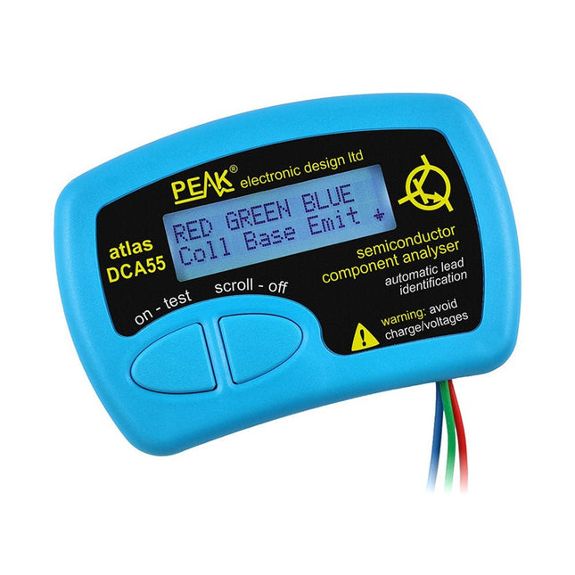
Peak Peak Atlas DCA55 Semiconductor Analyzer
The Peak Atlas DCA55 is great for automatically identifying the type of semiconductor on the test leads as well as the pinout and many other parameters. Supports transistors MOSFETs, JFETs (gate pin only can be identified), diodes, LEDs and lots more. Automatically identifies type of component, pinout and other important parameters. Now features transistor leakage measurement and Germanium/Silicon identification. Component Support Bipolar transistors (NPN/PNP inc Silicon/Germanium) Darlington transistors (NPN/PNP) Enhancement mode MOSFETs (N-Ch and P-Ch) Depletion mode MOSFETs (N-Ch and P-Ch) Junction FETs (N-Ch and P-Ch). Only gate lead identified Diodes and diode networks (2 and 3 lead types) LEDs and bi-colour LEDs (2 lead and 3 lead types) Low power sensitive Triacs and Thyristors (<5 mA trigger and hold) Measurements Part type identification Pinout identification BJT current gain (hFE) BJT base emitter voltage (Vbe) BJT collector leakage current MOSFET gate threshold voltage Diode forward voltage drop (Vf) Specifications Analyzer type Transistors, Diodes, LEDs, MOSFETs, JFETs Pinout detection Full pinout (only Gate on JFETs) Pinout configuration Connect any way round Transistor measurements Vbe, hFE, Iceo MOSFET measurements Vgs(on) Diode measurements Vf Probe type Universal grabber type Battery Single AAA cell (supplied). Life typically 1300 ops Test conditions Typically 5 mA, 5 V peak Display type Alphanumeric LCD (with backlight) Included Peak Atlas DCA55 Semiconductor Analyzer Comprehensive illustrated user guide Fitted universal hook probes AAA Alkaline battery Downloads Datasheet (EN) User Guide (EN) User Guide (IT)
€ 83,49
-
Elektor Publishing KiCad Like A Pro – Advanced Projects and Recipes
Mastering PCB design with real-world projects This book builts on KiCad Like a Pro – Fundamentals and Projects and aims to help you practice your new KiCad skills by challenging you in a series of real-world projects. The projects are supported by a comprehensive set of recipes with detailed instructions on how to achieve a variety of simple and complex tasks. Design the PCBs for a solar power supply, an LED matrix array, an Arduino-powered datalogger, and a custom ESP32 board. Understand the finer details of the interactive router, how to manage KiCad project teams with Git, how to use an autorouter on 2 and 4-layer PCBs, and much more. KiCad 8 is a modern, cross-platform application suite built around schematic and design editors. This stable and mature PCB tool is a perfect fit for electronic engineers and makers. With KiCad 8, you can create PCBs of any complexity and size without the constraints associated with the commercial packages. Here are the most significant improvements and features in KiCad 8, both over and under the hood: Modern user interface, completely redesigned from earlier versions Improved and customizable electrical and design rule checkers Theme editor allowing you to fully customize the look of KiCad on your screen Ability to import projects from Eagle, CADSTART, and more An improved and tightly integrated SPICE circuit simulator Autorouting with the Freerouting plugin Filters define which elements of a layout are selectable Enhanced interactive router helps you draw single tracks and differential pairs with precision New or enhanced tools to draw tracks, measure distances, tune track lengths, etc. Enhanced tool for creating filled zones A customizable coordinate system facilitates data exchange with other CAD applications Realistic ray-tracing capable 3D viewer Differential pair routing Rich repositories of symbol, footprint, and 3D shape libraries Python scripting API for programmatic customization and extensions Improved footprint wizard for fast custom footprints
€ 49,95
Members: € 44,96
-
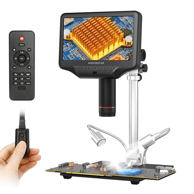
Andonstar Andonstar AD407 Pro 7" HDMI Digital Microscope
The Andonstar AD407 Pro microscope is suitable for various applications such as soldering SMDs or repair work. The microscope has a large adjustable 7" LCD display and comes with a remote. Compared to AD407, AD407 Pro offers an extra-high stand, which makes soldering of components even easier. Specifications Screen size 7 inch (17.8 cm) Image sensor 4 MP Video output UHD 2880x2160 (24fps)FHD 1920x1080 (60fps/30fps)HD 1280x720 (120fps) Video format MP4 Magnification Up to 270 times (27 inch HDMI monitor) Photo resolution Max. 12 MP (4032x3024) Photo format JPG Focus range Min. 5 cm Frame Rate Max. 120fps Video interface HDMI Storage microSD card (up to 64 GB) Power source 5 V DC Light source 2 LEDs with the stand Stand size 20 x 18 x 32 cm Included 1x Andonstar AD407 Pro Digital Microscope 1x Metal stand with 2 LEDs 1x UV filter (already assembled in the lens) 1x IR remote 1x Switch cable 1x Power adapter 1x Wrench 2x Metal clips 1x HDMI cable 1x Manual Downloads Manual Model Comparison AD407 AD407 Pro AD409 AD409 Pro-ES Screen size 7 inch (17.8 cm) 7 inch (17.8 cm) 10.1 inch (25.7 cm) 10.1 inch (25.7 cm) Image sensor 4 MP 4 MP 4 MP 4 MP Video output 2160p 2160p 2160p 2160p Interfaces HDMI HDMI USB, HDMI, WiFi USB, HDMI, WiFi Video format MP4 MP4 MP4 MP4 Magnification Up to 270x Up to 270x Up to 300x Up to 300x Photo resolution Max. 4032x3024 Max. 4032x3024 Max. 4032x3024 Max. 4032x3024 Photo format JPG JPG JPG JPG Focus distance Min. 5 cm Min. 5 cm Min. 5 cm Min. 5 cm Frame rate Max. 120f/s Max. 120f/s Max. 120f/s Max. 120f/s Storage microSD card microSD card microSD card microSD card PC support No No Windows Windows Mobile connection No No WiFi + Measurement WiFi + Measurement Power source 5 V DC 5 V DC 5 V DC 5 V DC Light source 2 LEDs with the stand 2 LEDs with the stand 2 LEDs with the stand 2 LEDs with the stand Endoscope No No No Yes Stand size 20 x 12 x 19 cm 20 x 18 x 32 cm 18 x 20 x 30 cm 18 x 20 x 32 cm Weight 1.6 kg 2.1 kg 2.2 kg 2.5 kg
€ 226,27
-
Elektor Digital C Programming with Arduino (E-book)
Technology is constantly changing. New microcontrollers become available every year. The one thing that has stayed the same is the C programming language used to program these microcontrollers. If you would like to learn this standard language to program microcontrollers, then this book is for you! Arduino is the hardware platform used to teach the C programming language as Arduino boards are available worldwide and contain the popular AVR microcontrollers from Atmel. Atmel Studio is used as the development environment for writing C programs for AVR microcontrollers. It is a full-featured integrated development environment (IDE) that uses the GCC C software tools for AVR microcontrollers and is free to download. At a glance: Start learning to program from the very first chapter No programming experience is necessary Learn by doing – type and run the example programs A fun way to learn the C programming language Ideal for electronic hobbyists, students and engineers wanting to learn the C programming language in an embedded environment on AVR microcontrollers Use the free full-featured Atmel Studio IDE software for Windows Write C programs for 8-bit AVR microcontrollers as found on the Arduino Uno and MEGA boards Example code runs on Arduino Uno and Arduino MEGA 2560 boards and can be adapted to run on other AVR microcontrollers or boards Use the AVR Dragon programmer/debugger in conjunction with Atmel Studio to debug C programs
€ 39,95
Members: € 35,96
-

Elektor Publishing Control Engineering with Fuzzy Logic
Practical Applications and Project with Arduino, ESP32, and RP2040 Immerse yourself in the fascinating world of control engineering with Arduino and ESP32! This book offers you a practical introduction to classic and modern control methods, including PID controllers, fuzzy logic, and sliding-mode controllers. In the first part, you will learn the basics of the popular Arduino controllers, such as the Arduino Uno and the ESP32, as well as the integration of sensors for temperature and pH measurement (NTC, PT100, PT1000, and pH sensor). You will learn how to use these sensors in various projects and how to visualize data on a Nextion TFT display. The course continues with an introduction to actuators such as MOSFET switches, H-bridges, and solid-state relays, which are used to control motors and actuators. You will learn to analyze and model controlled systems, including PT1 and PT2 control. The book focuses on the implementation of fuzzy and PID controllers for controlling temperature and DC motors. Both the Arduino Uno and the ESP32 are used. The sliding-mode controller is also introduced. In the second-to-last chapter, you will explore the basics of neural networks and learn how machine learning can be used on an Arduino. In the last chapter, there is a practical example of a fuzzy controller for feeding electricity into the household grid. This book is the perfect choice for engineers, students, and electronics engineers who want to expand their projects with innovative control techniques.
€ 44,95
Members: € 40,46
-

Elektor Digital H0W2: Get Started with the MAX78000FTHR Development Board (E-book)
Build your own AI microcontroller applications from scratch The MAX78000FTHR from Maxim Integrated is a small development board based on the MAX78000 MCU. The main usage of this board is in artificial intelligence applications (AI) which generally require large amounts of processing power and memory. It marries an Arm Cortex-M4 processor with a floating-point unit (FPU), convolutional neural network (CNN) accelerator, and RISC-V core into a single device. It is designed for ultra-low power consumption, making it ideal for many portable AI-based applications. This book is project-based and aims to teach the basic features of the MAX78000FTHR. It demonstrates how it can be used in various classical and AI-based projects. Each project is described in detail and complete program listings are provided. Readers should be able to use the projects as they are, or modify them to suit their applications. This book covers the following features of the MAX78000FTHR microcontroller development board: Onboard LEDs and buttons External LEDs and buttons Using analog-to-digital converters I²C projects SPI projects UART projects External interrupts and timer interrupts Using the onboard microphone Using the onboard camera Convolutional Neural Network
€ 32,95
Members: € 29,66
-

Elektor Digital Consumer Electronics Repair, Reuse and Recycling (E-book)
A Combat Guide against E-waste and Throwawayism This book is for anyone who enjoys tinkering with analog and digital hardware electronics. Regardless of the sophistication of your workspace, only basic tools are required to achieve truly satisfying results. It is intended as a reference guide among other hardware repair publications you may have in your library. However, the book goes a step further than most other repair guides in addressing issues in the modern era of discarded electronics called e-waste. E-waste should be put to good use. Producing anything new requires not just precious resources and labor, but also energy to make and deliver it to global retail shelves. Your talents and love of electronics can be put to good use by rescuing and resurrecting at least selected units from this endless stream of e-waste. Examples include either restoring through repair, or salvaging reusable electronic and mechanical components for your next project. Smart tips are provided throughout the book, and much information is tabulated for easy reference. The book expands age-old repair and hacking techniques applied for repair on the workbench into clever methods and applications to achieve effective results with discarded or “non-servicable” electronic consumer products. The final chapter provides real-life examples using all of the previously discussed content in a summarized form for each example repair type.
€ 32,95
Members: € 29,66
-

Elektor Digital Kickstart to Python 3 (E-book)
An Ultra-Rapid Programming Course This book serves as the very first step to for novices to learn Python programming. The book is divided into ten chapters. In the first chapter, readers are introduced to the basics of Python. It has the detailed instructions for installation on various platforms such as macOS, Windows, FreeBSD, and Linux. It also covers the other aspects of Python programming such as IDEs and Package Manager. The second chapter is where the readers get an opportunity to have a detailed hands-on with Python programming. It covers a group of built-in data structures popularly known as Python Collections. The third chapter covers the important concepts of strings, functions, and recursion. The fourth chapter focuses on the Object-Oriented Programming with Python. The fifth chapter discusses most commonly used custom data structures such as stack and queue. The sixth chapter spurs the creativity of the readers with Python’s Turtle graphics library. The seventh chapter explores animations and game development using the Pygame library. The eighth chapter covers handling data stored in a variety of file formats. The ninth chapter covers the area of Image processing with Wand library in Python. The tenth and the final chapter presents an array of assorted handy topics in Python. The entire book follows a step-by-step approach. The explanation of the topic is always followed by a detailed code example. The code examples are also explained in suitable detail and they are followed by the output in the form of text or screenshot wherever possible. Readers will become comfortable with Python programming language by closely following the concepts and the code examples in this book. The book also has references to external resources for readers to explore further. A download of the software code, and links to tutorial videos can be found on the Elektor website.
€ 29,95
Members: € 26,96
-

Elektor Digital LEDs, Lasers, and Sunlight (E-book)
Principles, Design, and Real-World Applications of Modern Photonics Light shapes our world—from the glow of a simple LED to the precision of a laser beam and the immense power of the sun. LEDs, Lasers, and Sunlight – Principles, Design, and Real-World Applications of Modern Photonics is your comprehensive guide to understanding, designing, and applying modern light technologies. This book takes you on a journey from the fundamentals of photonics—covering the nature of light, optical laws, and color theory—to real-world engineering with today’s most important light sources. You’ll explore how LEDs work, how to design efficient lighting systems, and how to tackle practical challenges such as thermal management, power supply design, and optical performance. Beyond illumination, the book opens doors to specialized applications: horticultural lighting for plant growth, infrared and ultraviolet technologies, modern display systems from LCD to MicroLED, and the fascinating world of lasers—from their physics to their use in medicine, industry, and communication. It also connects light engineering to sustainability through solar energy and thermal radiation. Written with a strong practical focus, this book bridges theory and application. Whether you are an engineer, student, or advanced hobbyist, you’ll gain the tools to turn concepts into working solutions—from selecting components to building complete systems. If you want to understand light not just as a phenomenon, but as a powerful engineering tool, this book will illuminate the way.
€ 49,95
Members: € 44,96
-

Elektor Publishing Wireless Power Design
From Theory to Practical Applications in Wireless Energy Transfer and Harvesting Wireless power transmission has gained significant global interest, particularly with the rise of electric vehicles and the Internet of Things (IoT). It’s a technology that allows the transfer of electricity without physical connections, offering solutions for everything from powering small devices over short distances to long-range energy transmission for more complex systems. Wireless Power Design provides a balanced mix of theoretical knowledge and practical insights, helping you explore the potential of wireless energy transfer and harvesting technologies. The book presents a series of hands-on projects that cover various aspects of wireless power systems, each accompanied by detailed explanations and parameter listings. The following five projects guide you through key areas of wireless power: Project 1: Wireless Powering of Advanced IoT Devices Project 2: Wireless Powered Devices on the Frontline – The Future and Challenges Project 3: Wireless Powering of Devices Using Inductive Technology Project 4: Wireless Power Transmission for IoT Devices Project 5: Charging Robot Crawler Inside the Pipeline These projects explore different aspects of wireless power, from inductive charging to wireless energy transmission, offering practical solutions for real-world applications. The book includes projects that use simulation tools like CST Microwave Studio and Keysight ADS for design and analysis, with a focus on practical design considerations and real-world implementation techniques.
€ 39,95
Members: € 35,96
-
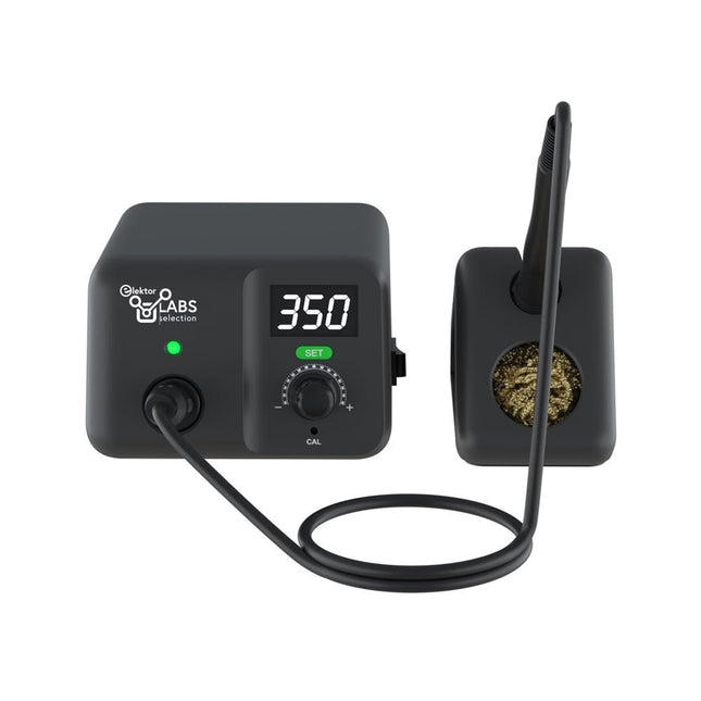
Eleshop AE970D Soldering Station (80 W)
Soldering station for precision soldering with actively heated soldering tip The AE970D soldering iron station is a 80 W high power tool to heat up to solder fastly. Its wide temperature range of 150-550°C (302-1022°F) could meet all your soldering needs. Thanks to its high performance plug-and-play integrated active tip, AE970D can reach melting point within 9 seconds. Patented close-loop automatic constant temperature control technology can ensure its soldering with high stability, excellent performance and precise accuracy. Features 80 W high power to enable fast heating up Wider temperature range of 150-550°C (302-1022°F) to meet all your soldering needs High performance plug-and-play integrated active tip, can reach melting point within 9 seconds Patented close-loop automatic constant temperature control technology to ensure high stability, excellent performance and precise accuracy Specifications Power 80 W Input voltage 110 VAC / 230 VAC Output voltage 25 VAC Temperature range 150-550°C (302-1022°F) Heating element T80 series integrated active heater Temperature stability ±1°C/±1.8°F (when temperature >200°C/400°F) Tip to ground resistance <2 Ω Tip to ground voltage <2 mV Power cord length 1 m Handle cable length 1.2 m Dimensions 148 x 120 x 85 mm Weight (main unit) 1.33 kg Included Main unit Soldering iron incl. soldering tip T80-D12 Iron stand Brass wool Manual
€ 95,00
-

Elektor Digital Control Engineering with Fuzzy Logic (E-book)
Practical Applications and Project with Arduino, ESP32, and RP2040 Immerse yourself in the fascinating world of control engineering with Arduino and ESP32! This book offers you a practical introduction to classic and modern control methods, including PID controllers, fuzzy logic, and sliding-mode controllers. In the first part, you will learn the basics of the popular Arduino controllers, such as the Arduino Uno and the ESP32, as well as the integration of sensors for temperature and pH measurement (NTC, PT100, PT1000, and pH sensor). You will learn how to use these sensors in various projects and how to visualize data on a Nextion TFT display. The course continues with an introduction to actuators such as MOSFET switches, H-bridges, and solid-state relays, which are used to control motors and actuators. You will learn to analyze and model controlled systems, including PT1 and PT2 control. The book focuses on the implementation of fuzzy and PID controllers for controlling temperature and DC motors. Both the Arduino Uno and the ESP32 are used. The sliding-mode controller is also introduced. In the second-to-last chapter, you will explore the basics of neural networks and learn how machine learning can be used on an Arduino. In the last chapter, there is a practical example of a fuzzy controller for feeding electricity into the household grid. This book is the perfect choice for engineers, students, and electronics engineers who want to expand their projects with innovative control techniques.
€ 34,95
Members: € 31,46
-
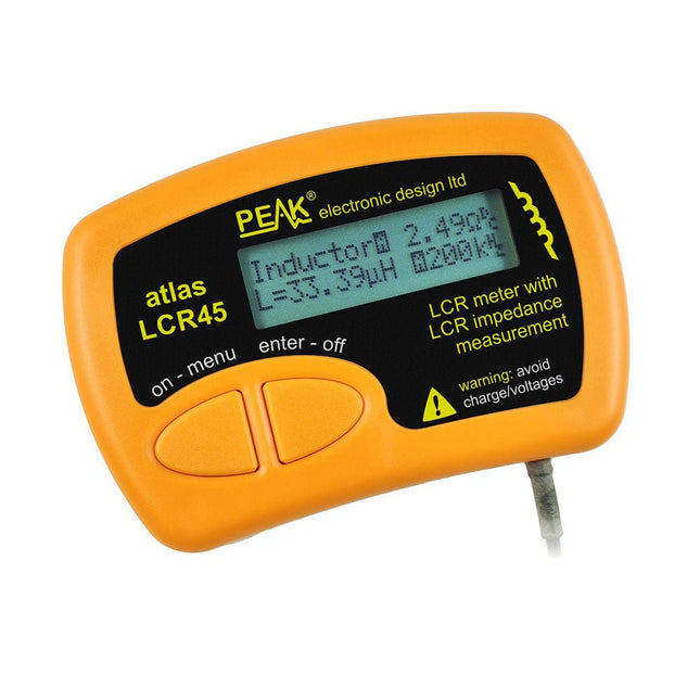
Peak Peak Atlas LCR45 LCR Meter
The Peak Atlas LCR45 does everything that the popular LCR40 does, but it has some significant enhancements. The LCR45 features a new high capacity micro and high resolution ADCs. LCR45 incorporates advanced maths, based on Complex Impedance analysis. This allows for enhanced component value measurement as well as a comprehensive and detailed impedance display. Features Supplied with gold plated removable hook probes Fluid measurements with hold function Automatic or manual component type Automatic or manual test frequency, DC, 1 kHz, 15 kHz or 200 kHz Enhanced measurement resolution: 0.2 µH, 0.2 pF and 0.2 Ohms Easy menu system for user settings Enhanced compensation for component parasitics and losses (such as core losses etc) Automatic or manual power-off Specifications Analyser type LCR and component impedance Component types Auto/Manual for L,C & R Measurement types Inductance, Capacitance and Resistance Other measurements Complex impedance/admittance More measurements Magnitude and Phase of impedance Inductance range 0uH to 2H Capacitance range 0 pF to 10000 uF Resistance range 0R to 2MR Test frequency Auto and manual: DC, 1 kHz, 15 kHz, 200 kHz Display type Alphanumeric LCD (not backlit) Measurement scheme Continuous (with optional hold) Battery GP23 (12 V/55 mAH type), ~700 ops Included LCR45 Passive Component Impedance Meter 2 mm plugs and sockets and removeable hook probes Comprehensive illustrated user guide 2 Batteries, one installed and one spare. GP23 Alkaline battery. (12 V/55 mAH) Downloads Datasheet (EN) User Guide (EN) User Guide (FR) User Guide (IT)
€ 131,89
-

BusBoard BreadBoard BB830T (830 Tie Points) Transparent
The BB830T is a solderless (plug-in) transparent breadboard with 830 connection tie-points (i.e. 830 wire insertion holes). It has 4 power rails. Solderless breadboards are great for building and testing new circuits because parts can be easily inserted and removed. They are completely re-usable. The BB830T has a 630 tie-point IC-circuit area plus four 50 tie-point power rails. Specifications 830 tie points total: 630 tie-point IC-circuit area plus two 100 tie-point distribution strips providing 4 power rails. ABS plastic/transparent body with black printed legend. Color legend on distribution strips. Contacts are Phosphor Bronze with Plated Nickel Finish, rated for 50,000 insertions. Rated at 36 Volts, 2 Amps. Insertion Wire Size is 21 to 26 AWG, 0.016 to 0.028 inches diameter (0.4 to 0.7mm diameter). Peelable adhesive tape backing provided for attaching to a surface. Metal back plate provided.
€ 10,29
-

Elektor Digital Inside an Open-Source Processor (E-book)
An Introduction to RISC-V RISC-V is an Instruction Set Architecture (ISA) that is both free and open. This means that the RISC-V ISA itself does not require a licensing fee, although individual implementations may do so. The RISC-V ISA is curated by a non-profit foundation with no commercial interest in products or services that use it, and it is possible for anyone to submit contributions to the RISC-V specifications. The RISC-V ISA is suitable for applications ranging from embedded microcontrollers to supercomputers. This book will first describe the 32-bit RISC-V ISA, including both the base instruction set as well as the majority of the currently-defined extensions. The book will then describe, in detail, an open-source implementation of the ISA that is intended for embedded control applications. This implementation includes the base instruction set as well as a number of standard extensions. After the description of the CPU design is complete the design is expanded to include memory and some simple I/O. The resulting microcontroller will then be implemented in an affordable FPGA development board (available from Elektor) along with a simple software application so that the reader can investigate the finished design.
€ 32,95
Members: € 29,66
-

Elektor Publishing Automotive Sensors and Actuators
Principles, Systems, and Electronics This handbook provides a detailed study of the sensors and actuators at the heart of modern vehicle electronics. It begins with basic electrical and electronic concepts, introducing the principles and terminology essential for understanding automotive systems. The book explores sensors and actuators on a system-by-system basis, including: Fundamentals of electrical engineering, electromagnetic phenomena, and motor principles Passive and active electronic components, integrated circuits, protection devices, and automotive-grade electronics Sensor characteristics, signal conditioning, ADCs, PWM and frequency outputs, and interface adaptation Automotive communication links and protocols, including LIN and SENT Engine sensors: air mass, pressure, temperature, speed, position, exhaust and emissions-related sensors Transmission sensors for manual and automatic systems Steering and suspension sensors for conventional and active systems Vehicle body and electrical system sensors for comfort, climate, access, and monitoring functions Engine actuators such as throttle bodies, injectors, turbo actuators, EGR systems, ignition components, and pumps Transmission, brake, steering, suspension, and body actuators Identification and coding of electronic components and packages commonly used in automotive applications The structure and operating principles of each component are explained, with relevant electronic circuitry illustrated. Its system-oriented organization and practical focus make it a valuable reference for understanding, testing, and troubleshooting automotive electronic systems.
€ 39,95
Members: € 35,96
-

Elektor Digital The Raspberry Pi Zero 2 W GO! Book (PDF)
A Fast-Lane Ride From Concept to Project The core of the book explains the use of the Raspberry Pi Zero 2 W running the Python programming language, always in simple terms and backed by many tested and working example projects. On part of the reader, familiarity with the Python programming language and some experience with one of the Raspberry Pi computers will prove helpful. Although previous electronics experience is not required, some knowledge of basic electronics is beneficial, especially when venturing out to modify the projects for your own applications. Over 30 tested and working hardware-based projects are given in the book, covering the use of Wi-Fi, communication with smartphones and with a Raspberry Pi Pico W computer. Additionally, there are Bluetooth projects including elementary communication with smartphones and with the popular Arduino Uno. Both Wi-Fi and Bluetooth are key features of the Raspberry Pi Zero 2 W. Some of the topics covered in the book are: Raspberry Pi OS installation on an SD card Python program creation and execution on the Raspberry Pi Zero 2 W Software-only examples of Python running on the Raspberry Pi Zero 2 W Hardware-based projects including LCD and Sense HAT interfacing UDP and TCP Wi-Fi based projects for smartphone communication UDP-based project for Raspberry Pi Pico W communication Flask-based webserver project Cloud storage of captured temperature, humidity, and pressure data TFT projects Node-RED projects Interfacing to Alexa MQTT projects Bluetooth-based projects for smartphone and Arduino Uno communications
€ 32,95
Members: € 29,66
-

Elektor Publishing Apple Macintosh
20+ Macintosh Models, from 1984 to Today (History, Engineering, and Restoration) Apple is not like any other company. More than anyone else, it transformed technology into something people could desire, love, and even identify with—much like a luxury brand. Users were not only buying a tool; they were buying a vision, a way of life. At the center of this transformation stands the Macintosh. First introduced in 1984, it was radically different from everything before. With its graphical interface and mouse, it made computing approachable, even friendly. What now feels obvious—clicking on icons, dragging files, pointing instead of typing commands—was revolutionary at the time. The Macintosh not only changed the way people related to technology. The Macintosh forced the entire industry to rethink the way we use computers. This book tells that story through some of the most significant Macintosh models. Each one is presented not only in words but also in images, because these computers are more than technology—they are design icons, symbols of a unique vision. History, technical detail, and photography come together here, aiming to show each Macintosh as it truly deserves to be seen.
€ 79,95€ 59,95Best Price
-
Elektor Publishing Acoustics in Performance
All you need to know about good acoustics and sound systems in performance and worship spaces! Everyone knows that the ability to hear music in balance and to understand speech is essential in any space used for performance or worship. Unfortunately, in the early 21st century, we find that buildings with good acoustics are the exception rather than the rule. Much of the fault leading to this result can be traced to the widespread perception that acoustics is a black art. In fact, scientific acoustics as developed in the last century is a well-defined engineering practice that can lead to predictable excellent results. A basic, non-engineering understanding of acoustics will help building owners, theater managers, ministers and teachers of music, performers, and other professionals to achieve their goals of excellent acoustics in venues with which they work. Performers having a basic understanding of acoustics will be able to make the most of the acoustics of the venue in which they perform. This book helps those responsible for providing good acoustics in performance and worship spaces to understand the variables and choices entailed in proper acoustic design for performance and worship. Practicing acoustical consultants will find the book a useful reference as well. The level of presentation is comfortable and straightforward without being simplistic. If correct acoustical principles are incorporated into the design, renovation, and maintenance of performance and worship venues, good acoustics will be the result.
€ 29,95
Members: € 26,96


