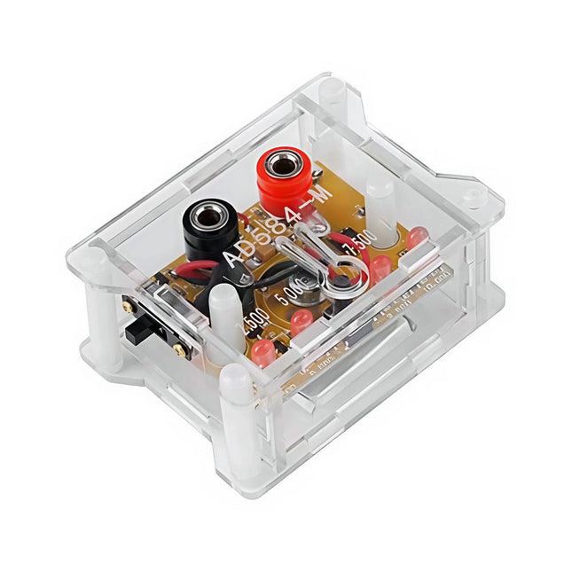
The AD584 4-ch Voltage Reference Module is designed to provide stable and accurate reference voltages of 2.5 V, 5 V, 7.5 V, and 10 V. It incorporates the AD584 integrated circuit, known for its high accuracy and stability.
Features
Multiple Output Voltages: The module can output four different reference voltages (2.5 V, 5 V, 7.5 V, and 10 V) accessible through a single port.
Microcontroller-based Switching: An onboard microcontroller facilitates switching between the four voltage outputs, with LED indicators displaying the active selection.
User-Friendly Operation: A single button allows for easy cycling through the available reference voltages.
Transparent Housing: The module is encased in a transparent housing, offering protection while allowing users to view the internal components.
Power Supply Options: It can be powered via a built-in lithium battery (not included) or through a 5 V DC input. A charging indicator provides status updates during charging.
Output Interface: Equipped with 4mm banana sockets for secure and reliable connections.
Included
1x AD584 4-ch Voltage Reference Module with Housing
Downloads
Datasheet
If you want to push the resolution limits of the V-One, these dispensing tips will help enable your experimental projects. This pack contains 4 extra fine nozzles with an internal diameter of 0.150 mm (6 mil).
Do not use with solder paste! It will clog!
This IPS 7.9-inch HDMI touch display with 400 x 1280 resolution, 170° wide viewing angle and built-in ferrite Hi-Fi speaker can be used as a secondary screen for chassis and also supports Raspberry Pi and Jetson Nano.
Features
7.9-inch IPS display with a hardware resolution of 400 x 1280.
Zinc alloy case, toughened glass panel with up to 6H hardness.
When working as a computer monitor, it supports Windows without a driver.
When working with Raspberry Pi, it supports Raspberry Pi OS / Ubuntu / Kali and Retropie, driver-free.
When working with Jetson Nano, it supports Ubuntu, driver-free.
Support backlight control for power saving.
Support 5-point capacitive touch control.
Specifications
Display size
7.9"
Viewing angle
170°
Resolution
400 x 1280 pixels
Display area
191.08 x 60.40 mm
IPS version solor gamut
62% NTSC
Max brightness
550 cd/m²
Backlight adjustment
Adjusted by the key/HID software
Contrast
900:1
Color depth
16.7M
Refresh rate
60 Hz
Power port
USB-C
Display port
HDMI interface
Dimensions
211 x 73 x 20 mm
Included
1x 7.9-inch Side Monitor
1x HDMI to Micro HDMI adapter
1x USB Type-A to Type-C cable (1 m)
1x HDMI flat cable (1 m)
2x Nonskid rubber feet
Downloads
Wiki
The LILYGO T-Display-S3 Long is a versatile development board powered by the ESP32-S3R8 dual-core LX7 microprocessor. It features a 3.4-inch capacitive touch TFT LCD with a resolution of 180x640 pixels, providing a responsive interface for various applications.
This board is ideal for developers seeking a compact yet powerful solution for projects requiring touch input and wireless communication. Its compatibility with popular programming environments ensures a smooth development experience.
Specifications
MCU
ESP32-S3R8 Dual-core LX7 microprocessor
Wireless Connectivity
Wi-Fi 802.11, BLE 5 + BT Mesh
Programming Platform
Arduino IDE, VS Code
Flash
16 MB
PSRAM
8 MB
Bat voltage detection
IO02
Onboard functions
Boot + Reset Button, Battery Switch
Display
3.4" Capacitive Touch TFT LCD
Color depth
565, 666
Resolution
180 x 640 (RGB)
Working power supply
3.3 V
Interface
QSPI
Included
1x T-Display S3 Long
1x Power cable
2x STEMMA QT/Qwiic interface cable (P352)
1x Female pin (double row)
Downloads
GitHub
This set contains 3 nozzles for Hot Air Rework Stations such as ZD-8922 or ZD-8968.
Included
1x Hot air nozzle 79-3911
1x Hot air nozzle 79-3912
1x Hot air nozzle 79-3913
ArdiPi is the ultimate Arduino Uno alternative packed with powerful specs and exciting features in the Arduino Uno form factor. You can enjoy a low-cost solution with access to the largest support communities for Raspberry Pi.
ArdiPi variant is powered by Raspberry Pi Pico W. The built-in Wi-Fi and Bluetooth connectivity makes the board ideal for IoT projects or projects requiring wireless communication.
Features
Arduino Uno form factor, so you can connect 3.3 V compatible Arduino shields
SD card slot for storage and data transfer
Drag-and-drop programming using mass storage over USB
Multifunction GPIO breakout supporting general I/O, UART, I²C, SPI, ADC & PWM functions.
Multi-tune Buzzer to add audio alert into the project
SWD pins breakout for serial debugging
Multi-platform support like Arduino IDE, MicroPython, and CircuitPython.
Comes with HID support, so the device can simulate a mouse or keyboard
Specifications
Powered by RP2040 microcontroller which is a dual-core Arm Cortex-M0+ processor, 2 MB of onboard flash storage, 264 kB of RAM
On-board single-band 2.4 GHz wireless interfaces (802.11n) for WiFi and Bluetooth 5 (LE)
WPA3 & Soft access point supporting up to four clients
Operating voltage of pins 3.3 V and board supply 5 V
25 Multipurpose GPIOs breakout in Arduino style for easy peripheral interfacing
I²C, SPI, and UART communications protocol support
2 MB of onboard Flash memory
Cross-platform development and multiple programming language support
If you’re looking for a simple way to start soldering or just want to make your own Dasduino, this soldering set is a great opportunity. "Make your own Dasduino CORE" is an educational set for learning the skill of soldering, with which you end up with a functional microcontroller board. As with the other SMD versions of the Dasduino CORE boards we offer, the possibilities are endless.
It is based on the ATmega328P microcontroller, and all SMD components are already soldered on the board. The set also includes a THT socket for the microcontroller, which simplifies the replacement of the microcontroller should it ever become necessary.
Included
1x PCB
7x Capacitors (100nF)
4x Capacitors (2.2uF)
2x Capacitors (22pF)
5x Resistors (2.2 kOhm)
5x Resistors (10 kOhm)
3x Resistors (1 kOhm)
1x Resistor (100 kOhm)
1x Resistor (100 ohm)
1x JST battery connector
1x LED (purple)
1x LED (white)
1x LED (blue)
1x LED (red)
1x LED (orange)
1x Socket for ATmega328P
1x ATmega328P microcontroller
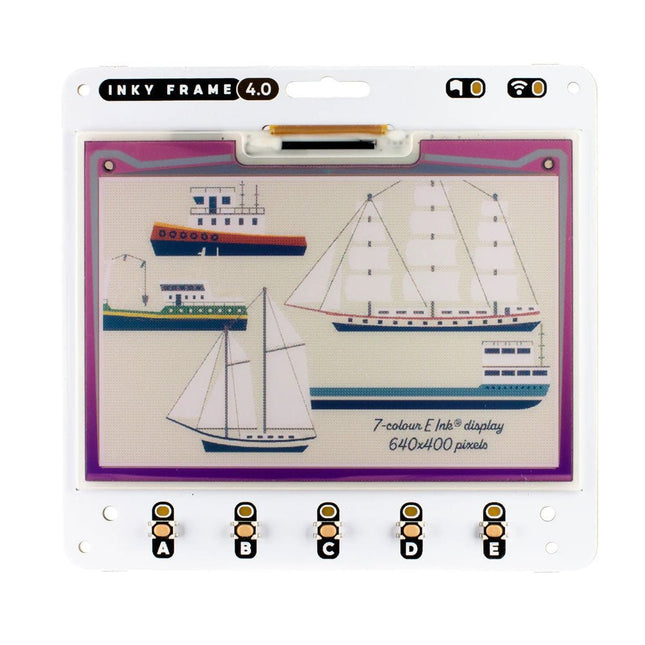
Inky Frame 4.0' features a vibrant E Ink display with 640 x 400 pixels of tightly packed seven colour goodness – that's almost as many pixels as on the 5.7' Inky Frame, but squished tidily into a smaller footprint. There's five buttons with LED indicators for interacting with the display, two Qw/ST connectors for plugging in breakouts and a micro SD card slot for storage of capybara photos or other vital files.
Every Inky Frame comes with a pair of sleek little metal legs so you can stand it up on your desk. There's also a battery connector so you can power it without annoying trailing wires, and some neato power saving features that mean you can run it from batteries for ages.
Inky Frame 4.0' is great for:
An ultra readable, low power consumption home automation dashboard
Displaying stylised photos, pop art images or favourite comic panels.
Showing cute graphs and readouts from local or wirelessly connected sensors
Displaying fascinating data from online APIs.
Features
Raspberry Pi Pico W Aboard
Dual Arm Cortex M0+ running at up to 133 Mhz with 264 kB of SRAM
2 MB of QSPI flash supporting XiP
Powered and programmable by USB micro-B
2.4 GHz wireless
4.01' EPD display (640 x 400 pixels)
E Ink Gallery Palette 4000 ePaper
ACeP (Advanced Color ePaper) 7-color with black, white, red, green, blue, yellow, orange.
Ultra wide viewing angles
Ultra low power consumption
Dot pitch – 0.135 x 0.135 mm
5x Tactile buttons with LED indicators
Two Qw/ST connectors for attaching breakouts
microSD card slot
Dedicated RTC chip (PCF85063A) for deep sleep/wake
Fully assembled (no soldering required)
C/C++ and MicroPython libraries
Schematic
Included
1x Inky Frame 4.0' (incl. Pico W)
2x Metal legs
Downloads
MicroPython
(Learn) Getting Started with Inky Frame
(Readme) Installing MicroPython
(Readme) MicroPython FAQs (and troubleshooting)
Download pirate-brand MicroPython (you'll want the Inky Frame.uf2)
MicroPython examples
PicoGraphics function reference
C/C++
C examples
Picographics function reference
The Arduino Nano 33 BLE Sense Rev2 with headers is Arduino’s 3.3 V AI enabled board in the smallest available form factor with a set of sensors that will allow you without any external hardware to start programming your next project, right away.
With the Arduino Nano 33 BLE Sense Rev2, you can:
Build wearable devices that using AI can recognize movements.
Build a room temperature monitoring device that can suggest or modify changes in the thermostat.
Build a gesture or voice recognition device using the microphone or the gesture sensor together with the AI capabilities of the board.
Differences between Rev1 and Rev2
Replacement of IMU from LSM9DS1 (9 axis) for a combination of two IMUs (BMI270 – 6 axis IMU and BMM150 – 3 axis IMU)
Replacement of temperature and humidity sensor from HTS221 for HS3003
Replacement of microphone from MP34DT05 to MP34DT06JTR
Replacement of power supply MPM3610 for MP2322
Addition of VUSB soldering jumper on the top side of the board
New test point for USB, SWDIO and SWCLK
Specifications
Microcontroller
nRF52840 (datasheet)
Operating Voltage
3.3 V
Input Voltage (limit)
21 V
DC Current per I/O Pin
15 mA
Clock Speed
64 MHz
CPU Flash Memory
1 MB (nRF52840)
SRAM
256 KB (nRF52840)
EEPROM
None
Digital Input / Output Pins
14
PWM Pins
All digital pins
UART
1
SPI
1
I²C
1
Analog Input Pins
8 (ADC 12 bit 200 k samples)
Analog Output Pins
Only through PWM (no DAC)
External Interrupts
All digital pins
LED_BUILTIN
13
USB
Native in the nRF52840 Processor
IMU
BMI270 (datasheet) and BMM150 (datasheet)
Microphone
MP34DT06JTR (datasheet)
Gesture, light, proximity, color
APDS9960 (datasheet)
Barometric pressure
LPS22HB (datasheet)
Temperature, humidity
HS3003 (datasheet)
Downloads
Datasheet
Schematics
Inventor 2040 W is a multi-talented board that does (almost) everything you might want a robot, prop or other mechanical thing to do. Drive a couple of fancy motors with encoders attached? Yep! Add up to six servos? Sure? Attach a little speaker so you can make noise? No problem! It's also got a battery connector so you can power your inventions from AA/AAA or LiPo batteries and carry your miniature automaton/animated top hat/treasure chest that growls at your enemies around with you untethered.You also get a ton of options for hooking up sensors and other gubbins – there's two Qw/ST connectors (and an unpopulated Breakout Garden slot) for attaching breakouts, three ADC pins for analog sensors, photoresistors and such, and three spare digital GPIO you could use for LEDs, buttons or digital sensors. Speaking of LEDs, the board features 12 addressable LEDs (AKA Neopixels) – one for each servo and GPIO/ADC channel.Features
Raspberry Pi Pico W Aboard
Dual Arm Cortex M0+ running at up to 133 Mhz with 264 kB of SRAM
2 MB of QSPI flash supporting XiP
Powered and programmable by USB micro-B
2.4 GHz wireless
2 JST-SH connectors (6 pin) for attaching motors
Dual H-Bridge motor driver (DRV8833)
Per motor current limiting (425 mA)
Per motor direction indicator LEDs
2 pin (Picoblade-compatible) connector for attaching speaker
JST-PH (2 pin) connector for attaching battery (input voltage 2.5-5.5 V)
6 sets of header pins for connecting 3 pin hobby servos
6 sets of header pins for GPIO (3 of which are ADC capable)
12x addressable RGB LEDs/Neopixels
User button
Reset button
2x Qw/ST connectors for attaching breakouts
Unpopulated headers for adding a Breakout Garden slot
Fully assembled
No soldering required (unless you want to add the Breakout Garden slot).
C/C++ and MicroPython libraries
Schematic
Downloads
Download pirate-brand MicroPython
Getting Started with Raspberry Pi Pico
Motor function reference
Servo function reference
MicroPython examples
C++ examples
The SparkFun MicroMod mikroBUS Carrier Board takes advantage of the MicroMod, Qwiic, and mikroBUS ecosystems making it easy to rapidly prototype with each of them, combined. The MicroMod M.2 socket and mikroBUS 8-pin header provide users the freedom to experiment with any Processor Board in the MicroMod ecosystem and any Click board in the mikroBUS ecosystem, respectively. This board also features two Qwiic connectors to seamlessly integrate hundreds of Qwiic sensors and accessories into your project. The mikroBUS socket comprises a pair of 8-pin female headers with a standardized pin configuration. The pins consist of three groups of communications pins (SPI, UART and I²C), six additional pins (PWM, Interrupt, Analog input, Reset and Chip select), and two power groups (3.3 V and 5 V). While a modern USB-C connector makes programming easy, the Carrier Board is also equipped with a MCP73831 Single-Cell Lithium-Ion/Lithium-Polymer Charge IC so you can charge an attached single-cell LiPo battery. The charge IC receives power from the USB connection and can source up to 450 mA to charge an attached battery. Features M.2 MicroMod (Processor Board) Connector USB-C Connector 3.3 V 1 A Voltage Regulator 2x Qwiic Connectors mikroBUS Socket Boot/Reset Buttons Charge Circuit JTAG/SWD PTH Pins Downloads Schematic Eagle Files Board Dimensions Hookup Guide Getting Started with Necto Studio mikroBUS Standard Qwiic Info Page GitHub Hardware Repo
The Ynvisible Segment E-Paper Displays are thin & flexible, sunlight readable, very easy to operate, and that they are the most energy-efficient display technology on the market for most applications. Get started today! Evaluate the ultra-low-power, thin and flexible Segment E-Paper Displays. The kit contains display designs and includes a manual display driver as well as a display driver with I²C interface. Display parameters White Reflectance 40% Contrast Ratio (Yb/Yd) 1:3 Angle Dependency No, lambertian Thickness 300 µm Graphical layout Segments Segment dimensions 1-100 mm Response time 100-1000 ms Power parameters Driving voltage 1.5 V Driving method Direct drive Energy consumption 1 mJ/cm^2 Pulse energy 0.25 mJ/cm^2 Image retention w/o power 1-5 minutes Operating conditions -20°C - +60°C Activations/Cycles 1.000.000 Included
Ynvisible Segment Displays (Segmented e-paper displays with different layouts, shapes, and symbols, suitable for testing and evaluation.) 3 single-digit display 1 double-digit display 5 single-segment/icon displays 4 progress bars (7-segment and 3-segment)
Manual Display Clicker (Manual display controller for ON/OFF operations)
Display Driver and Software Library (Dedicated display driver with I²C communication interface. Compatible with Arduino and other easy-to-use development boards.)
Flexible Display Adapter (For convenient connection of the flexible displays on a plastic substrate to rigid electronics (such as development boards), using a FFC/FPC connector.) Downloads Datasheet Guide & Instructions
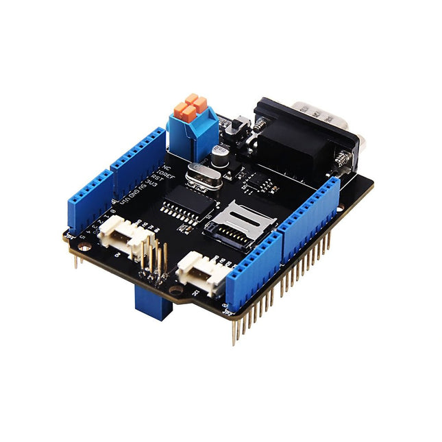
Features Implements CAN V2.0B at up to 1 Mb/s Industrial standard 9 pin sub-D connector OBD-II and CAN standard pinout selectable. Changeable chip select pin Changeable CS pin for TF card slot Changeable INT pin Screw terminal that easily to connect CAN_H and CAN_L Arduino Uno pin headers Micro SD card holder 2 Grove connectors (I2C and UART) SPI Interface up to 10 MHz Standard (11 bit) and extended (29 bit) data and remote frames Two receive buffers with prioritized message storage
This Grove - PIR Motion Sensor(Passive Infrared Sensor) can detect infrared signals caused by motion. If the PIR sensor notices the infrared energy, the motion detector is triggered and the sensor outputs HIGH on its SIG pin. The detecting range and response speed can be adjusted by 2 potentiometers soldered on its circuit board, The response speed is from 0.3s - 25s, and max 6 meters of detecting range. The Grove - PIR Motion Sensor(Passive Infrared Sensor) is an easy-to-use motion sensor with Grove compatible interface. Simply connecting it to Base Shield and programming it, it can be used as a suitable motion detector for Arduino projects. For example, the PIR Motion Sensor is commonly used in security alarm systems and automatic lighting applications. Features Grove compatible interface Voltage range: 3 V – 5 V Size: 20 mm x 40 mm Detecting angle: 120 degree Detecting Max distance: 6m (3m by default) Adjustable detecting distance and holding time Applications Motion Sensor Motion Detector Security Alarm System Human Detection System Technical Specifications Dimensions 40 mm x 20 mm x 15 mm Weight 12 g Battery Exclude Voltage range 3 V – 5 V Detecting angle 120 degree Detecting distance max 6m (3m by default)
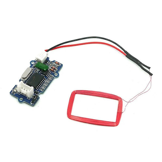
Features Selectable output format: Uart or Wiegand. 4Pins Electronic Brick Interface High Sensitivity Specifications Dimensions: 44 mm x 24 mm x9.6 mm Weight: 15 g Battery: Exclude Voltage: 4.75 V - 5.25 V Working Frequency: 125 kHz Sensing Distance(Max): 70 mm TTL Output: 9600 baud rate, 8 data bits, 1 stop bit, and no verify bit Wiegand Output: 26 bits Wiegand format, 1 even verify bit, 24 data bits, and 1 odd verify bit
The DiP-Pi WiFi Master is an Advanced WiFi connectivity System with sensors embedded interfaces that cover most of possible needs for IoT application based on Raspberry Pi Pico. It is powered directly from the Raspberry Pi Pico VBUS. The DiP-Pi WiFi Master contains Raspberry Pi Pico embedded RESET button as also ON/OFF Slide Switch that is acting on Raspberry Pi Pico Power Sources.
The DiP-Pi WiFi Master is equipped with WiFi ESP8266 Clone module with embedded antenna. This feature open a wide range of IoT applications based on it.
In Addition to all above features DiP-Pi WiFi Master is equipped with embedded 1-wire, DHT11/22 sensors, and micro–SD Card interfaces. Combination of the extended powering, battery, and sensors interfaces make the DiP-Pi WiFi Master ideal for IoT applications like data logger, plants monitoring, refrigerators monitoring etc.
DiP-Pi WiFi Master is supported with plenty of ready to use examples written in Micro Python or C/C++.
Specifications
General
Dimensions 21 x 51 mm
Raspberry Pi Pico pinout compatible
Independent Informative LEDs (VBUS, VSYS, V3V3)
Raspberry Pi Pico RESET Button
ON/OFF Slide Switch acting on Raspberry Pi Pico Powering Source
Embedded 3.3 V @ 600 mA LDO
ESP8266 Clone WiFi Connectivity
ESP8266 Firmware Upload Switch
Embedded 1-wire Interface
Embedded DHT-11/22 Interface
Powering Options
Raspberry Pi Pico micro-USB (via VBUS)
Embedded Peripherals and Interfaces
Embedded 1-wire interface
Embedded DHT-11/22 Interface
Micro SD Card Socket
Programmer Interface
Standard Raspberry Pi Pico C/C++
Standard Raspberry Pi Pico Micro Python
Case Compatibility
DiP-Pi Plexi-Cut Case
Informative LEDs
VB (VUSB)
VS (VSYS)
V3 (V3V3)
System Protection
Direct Raspberry Pi Pico Hardware Reset Button
PPTC 500 mA @ 18 V fuse on EPR
EPR/LDO Over Temperature protection
EPR/LDO Over Current protection
System Design
Designed and Simulated with PDA Analyzer with one of the most advanced CAD/CAM Tools – Altium Designer
Industrial Originated
PCB Construction
2 ozcopper PCB manufactured for proper high current supply and cooling
6 mils track/6 mils gap technology 2 layers PCB
PCB Surface Finishing – Immersion Gold
Multi-layer Copper Thermal Pipes for increased System Thermal Response and better passive cooling
Downloads
Datasheet
Manual
The board's main processor is a low-power ARM Cortex-M0 32-bit SAMD21, like in the other boards within the Arduino MKR family. The WiFi and Bluetooth connectivity is performed with a module from u-blox, the NINA-W10, a low-power chipset operating in the 2.4 GHz range. On top of that, secure communication is ensured through the Microchip ECC508 crypto chip. Besides that, you can find a battery charger, and an RGB LED on-board.
Official Arduino WiFi Library
You can get your board to connect to any kind of existing WiFi network, or use it to create your own Arduino Access Point. The specific set of examples we provide for the MKR WiFi 1010 can be consulted at the WiFiNINA library reference page.
Compatible with other Cloud Services
It is also possible to connect your board to different Cloud services, Arduino's own among others. Here are some examples of how to get the MKR WiFi 1010 to connect to:
Blynk: a simple project from the Arduino community connecting to Blynk to operate your board from a phone with little code
IFTTT: in-depth case of building a smart plug connected to IFTTT
AWS IoT Core: Arduino made this example on how to connect to Amazon Web Services
Azure: visit this GitHub repository explaining how to connect a temperature sensor to Azure's Cloud
Firebase: you want to connect to Google's Firebase, this Arduino library will show you how
Specifications
Microcontroller
SAMD21 Cortex-M0+ 32bit low power ARM MCU
Radio Module
u-blox NINA-W102
Power Supply
5 V
Secure Element
ATECC508
Supported Battery
Li-Po Single Cell, 3.7 V, 1024 mAh Minimum
Operating Voltage
3.3 V
Digital I/O Pins
8
PWM Pins
13
UART
1
SPI
1
I2C
1
Analog Input Pins
7
Analog Output Pins
1
External Interrupts
10
Flash Memory
256 KB
SRAM
32 KB
EEPROM
no
Clock Speed
32.768 kHz, 48 MHz
LED_Builtin
6
USB
Full-Speed USB Device and embedded Host
Length
61.5 mm
Width
25 mm
Weight
32 g
These are some of our favourite sensors from each category. But wait, there's more! The SparkFun Sensor Kit now includes several of our sensor boards that feature the Qwiic Connect System for rapid prototyping!
This version of the kit has received a complete overhaul!
This huge assortment of sensors makes an amazing gift for that exceptional electronics enthusiast in your life!
Included
Large Piezo Vibration Sensor (With Mass): A flexible film able to sense for vibration, touch, shock, etc. When the film moves back and forth an AC wave is created, with a voltage of up to ±90.
Reed Switch: Senses magnetic fields, makes for a great non-contact switch.
0.25' Magnet Square: Plays nicely with the reed switch. Embed the magnet into stuffed animals or inside a box to create a hidden actuator to the reed switch.
0.5' Force Sensitive Resistor: A force-sensing resistor with a 0.5' diameter sensing area. Great for sensing pressure (i.e., if it's being squeezed).
Flex Sensor (2.2'): As the sensor is flexed, the resistance across the sensor increases. Useful for sensing motion or positioning.
SoftPot: These are very thin variable potentiometers. By pressing on various positions along the strip, you vary the resistance.
Mini Photocell: The photocell will vary its resistance based on how much light it's exposed to. Will vary from 1kΩ in the light to 10kΩ in the dark.
PIR Motion Sensor: Easy-to-use motion detector with an analog interface. Power it with 5-12VDC, and you'll be alerted of any movement.
QRD1114 Optical Detector/Phototransistor: An all-in-one infrared emitter and detector. Ideal for sensing black-to-white transitions or can be used to detect nearby objects.
IR Diode: This LED can handle up to 50mA of current and outputs in the 940-950nm IR spectrum. Use to send signal to talk to the included IR receiver diode or just turn off your neighbor's TV.
IR Receiver Diode: This simple IR receiver will detect an IR signal coming from a standard IR remote control or the IR diode included in the kit.
Resistor 1.0M Ohm 1/4 Watt PTH: Two 1/4 Watt, +/- 5% tolerance PTH resistors. Commonly used in breadboards and perf boards. The large resistor helps dampen any voltage spikes when using the large piezo vibration sensor with a microcontroller.
Resistor 10K Ohm 1/4 Watt PTH – 20 pack (Thick Leads): 1/4 Watt, +/- 5% tolerance PTH resistors. Commonly used in breadboards and perf boards, these 10KΩ resistors make excellent pullups, pulldowns, and current limiters.
Resistor 330 Ohm 1/4 Watt PTH – 20 pack (Thick Leads): 1/4 Watt +/- 5% tolerance PTH resistors. Commonly used in breadboards and perf boards, these 330Ω resistors make excellent current-limiting resistors for LEDs.
SparkFun 9DoF IMU Breakout – ISM330DHCX, MMC5983MA (Qwiic): This breakout board includes a 3-axis accelerometer, 3-axis gyroscope, and 3-axis magnetometer. Connect this board over I2C using a Qwiic cable or solder wires or headers to the SPI pins to get started using one of the three sensors or using all three together to determine 3D orientation.
SparkFun Atmospheric Sensor Breakout – BME280 (Qwiic): The SparkFun BME280 Atmospheric Sensor Breakout is an easy way to measure barometric pressure, humidity, and temperature readings, all without taking up too much space.
SparkFun Indoor Air Quality Sensor – ENS160 (Qwiic): The SparkFun ENS160 Indoor Air Quality Sensor is a digital multi-gas sensor solution with four sensor elements that can be used in a wide range of applications including building automation, smart home, and HVAC.
SparkFun Capacitive Touch Slider – CAP1203 (Qwiic): This little board acts great as a non-mechanical button. Use the three pads on the board or connect your own input for a great touch button or slider with no moving parts.
Flexible Qwiic Cable (100 mm): Use these to connect up to four Qwiic boards in your kit.
RGB and Gesture Sensor (APDS-9960): This board does a little bit of everything. You can measure ambient light or color as well as detect proximity and do gesture sensing all over I2C.
Soil Moisture Sensor (with screw terminals): Ever wonder if your plant needs water? This sensor outputs an analog signal based on the resistance of the soil. Since water is conductive, the soil water content will be reflected in the soil resistance.
Sound Detector: Ever need to know if there is noise in an area? This board will not only tell you, but it will also output amplitude as well as the full audio signal.
Break Away Headers (Straight): Solder these pins to any of the breakouts to prototype on a breadboard. You'll want to solder these to boards that do not have Qwiic connectors such as the gesture sensor and sound detector.
The servo control is based on the SparkFun servo pHAT, and thanks to its I2C capabilities, this PWM add-on saves the Raspberry Pi's GPIO pins, allowing you to use them for other purposes. We have also provided a Qwiic connector for easy interfacing with the I²C bus using the Qwiic system. Whether you use the Auto pHAT with a Raspberry Pi, NVIDIA, Jetson Nano, Google Coral, or other SBC, it makes for a unique robotics addition and board with a 2x20 GPIO.
The DC motor control comes from the same 4245 PSOC and 2-channel motor ports system used on the SparkFun Qwiic Motor Driver. This provides 1.2A steady-state drive per channel (1.5A peak) and 127 levels of DC drive strength. The SparkFun Auto pHAT also supports up to two motor encoders thanks to the onboard ATTINY84A to provide more precise movement to your creation!
Additionally, the Auto pHAT has an on-board ICM-20948 9DOF IMU for all your motion-sensing needs. This enables your robot to access the 3-Axis Gyroscope with four selectable ranges, 3-Axis Accelerometer, again with four selectable ranges, and 3-axis magnetometer with an FSR of ±4900µT.
Power to the SparkFun Auto pHAT can be supplied through a USB-C connector or external power. This will power either the motors only or power the motors and the Raspberry Pi that is connected to the HAT. We've even added power protection circuits to the design to avoid damage to power sources.
Features
4245 PSOC and 2-channel motor ports programmable using Qwiic library
Onboard ATTINY84A supports up to two DC motor encoders
5V pass-through from RPi
Onboard ICM-20948 9DOF IMU for motion sensing accessible via Qwiic library
PWM control for up to four servos
Qwiic connector for expansion to full SparkFun Qwiic ecosystem
Designed for stacking, full header support & can use additional pHATs on top of it
Uninhibited access to the RPi camera connector & display connector.
USB-C for powering 5V rail (Motors/Servos/back powering Pi)
External power inputs broken out to PTH headers
Looking to dispense materials with a lower viscosity? These are the nozzles for you. Don't use this with our standard ink or solder paste... that will result in poor performance.
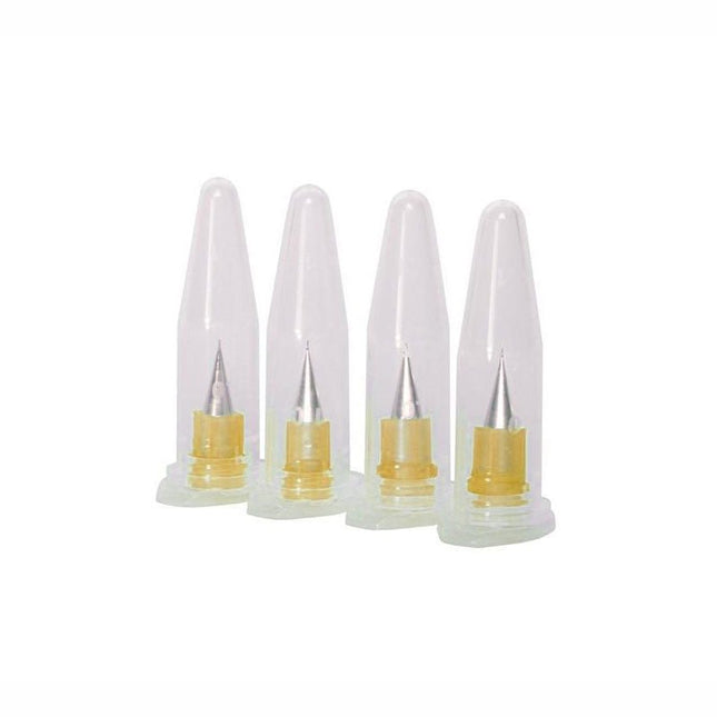
This pack contains 4 extra fine nozzles with an internal diameter of 0.100 mm (4 mil).
The software simulation of gauges, control-knobs, meters and indicators which behave just like real hardware components on a PC’s screen is known as virtual instrumentation.
In this book, the Delphi program is used to create these mimics and PIC based external sensors are connected via a USB/RS232 converter communication link to a PC.
Detailed case studies in this Book include a virtual compass displayed on the PC’s screen, a virtual digital storage oscilloscope, virtual -50 to +125 degree C thermometer, and FFT sound analyser, a joystick mouse and many examples detailing virtual instrumentation Delphi components. Arizona’s embedded microcontrollers – the PIC's are used in the projects and include PIC16F84A, PIC16C71, DSPIC30F6012A, PIC16F877, PIC12F629 and the PIC16F887. Much use is made of Microchip’s 44 pin development board (a virtual instrument ‘engine)’, equipped with a PIC16F887 with an onboard potentiometer in conjunction with the PIC’s ADC to simulate the generation of a variable voltage from a sensor/transducer, a UART to enable PC RS232 communications and a bank of 8 LED's to monitor received data is also equipped with an ISP connector to which the ‘PICKIT 2’ programmer may easily be connected.
Full source code examples are provided both for several different PIC’s, both in assembler and C, together with the Pascal code for the Delphi programs which use different 3rd party Delphi virtual components.
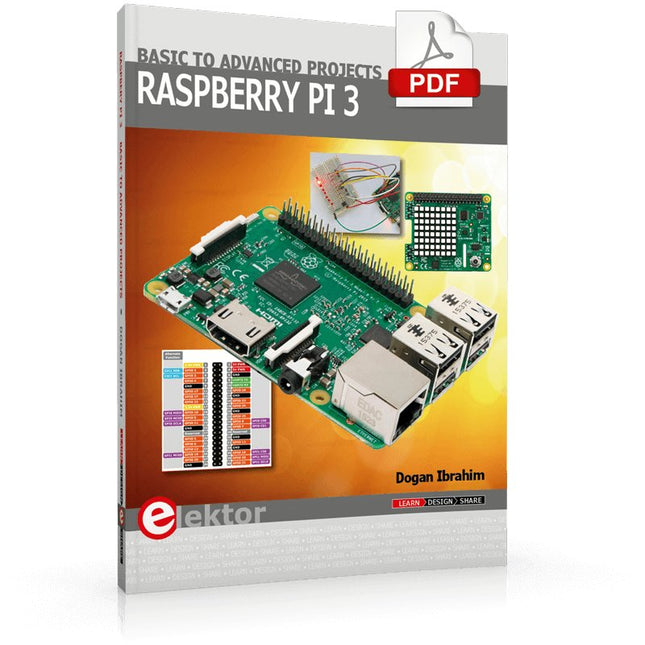
This ebook is about the Raspberry Pi 3 computer and its use in various control and monitoring applications. The book explains in simple terms and with tested and working example projects, how to configure the Raspberry Pi 3 computer, how to install and use the Linux operating system, and how to write hardware based applications programs using the Python programming language.
The nice feature of this book is that it covers many Raspberry Pi 3 based hardware projects using the latest hardware modules such as the Sense HAT, Swiss Pi, MotoPi, Camera module, and many other state of the art analog and digital sensors. An important feature of the Raspberry Pi 3 is that it contains on-board Bluetooth and Wi-Fi modules. Example projects are given in the book on using the Wi-Fi and the Bluetooth modules to show how real-data can be sent to the Cloud using the Wi-Fi module, and also how to communicate with an Android based mobile phone using the Bluetooth module.
The book is ideal for self-study, and is intended for electronic/electrical engineering students, practising engineers, research students, and for hobbyists. It is recommended that the book should be followed in the given Chapter order.
Over 30 projects are given in the book. All the projects in the book are based on the Python programming language and they have been fully tested. Full program listings of every project are given in the book with comments and full descriptions. Experienced programmers should find it easy to modify and update the programs to suit their needs.
The following sub-headings are given for each project to make it as easy as possible for the readers to follow the projects:
Project title
Description
Aim of the project
Raspberry Pi type
Block diagram
Circuit diagram
Program listing
Features Integrated Cold-Junction Compensation Supported Types (designated by NIST ITS-90): Type K, J, T, N, S, E, B and R Four Programmable Temperature Alert Outputs: Monitor Hot- or Cold-Junction Temperatures Detect rising or falling temperatures Up to 255°C of Programmable Hysteresis Programmable Digital Filter for Temperature Low Power Dimensions: 20 mm x 40 mm x 18 mm Weight: 18 g Application Petrochemical Thermal Management Hand-Held Measurement Equipment Industrial Equipment Thermal Management Ovens Industrial Engine Thermal Monitor Temperature Detection Racks Downloads Eagle Files Github library Datasheet