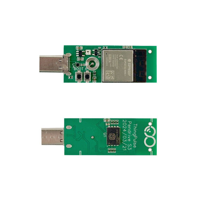
The ThingPulse Pendrive S3 is an ESP32-S3 device with USB-C plug, WS2812B RGB LED and 128 MB of flash. With the help of TinyUSB the ESP32-S3 can pretend to be many USB devices, such as:
USB Memory Stick
USB Keyboard
USB Mouse
Audio device
Video device
Networking device
Applications
As BadUSB Device with SuperWiFiDuck it can do KeyStroke injections
As WiFiDisk it can be mounted by any regular computer like a memory stick and synchronize the files on the disk to the cloud
As WiFiDongle it can add an additional WiFi networking device to any computer/phone
Included
ESP32-S3 PCB with
WS2812B RGB Led
Capacitive Touch Button (Spring)
USB Drive Plastic Enclosure
Downloads
CircuitPython
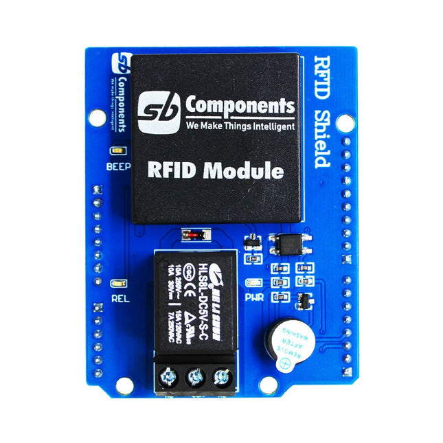
Designed with convenience and security in mind, the Ardi RFID Shield is based on the EM-18 module, operating at a frequency of 125 KHz. This shield allows you to easily integrate RFID (Radio Frequency Identification) technology into your projects, enabling seamless identification and access control systems.
Equipped with a powerful 1-channel optoisolated relay, the Ardi RFID Shield offers a reliable switching solution with a maximum DC rating of 30 V and 10 A, as well as an AC rating of 250 V and 7 A. Whether you need to control lights, motors, or other high-power devices, this shield provides the necessary functionality.
Additionally, the Ardi RFID Shield features an onboard buzzer that can be utilized for audio feedback, allowing for enhanced user interaction and system feedback. With the onboard 2-indication LEDs, you can easily monitor the status of RFID card detection, power supply, and relay activation, providing clear visual cues for your project's operation.
Compatibility is key, and the Ardi RFID Shield ensures seamless integration with the Arduino Uno platform. Paired with a read-only RFID module, this shield opens up a world of possibilities for applications such as access control systems, attendance tracking, inventory management, and more.
Features
Onboard 125 kHz EM18 RFID small, compact module
Onboard High-quality relays Relay with Screw terminal and NO/NC interfaces
Shield compatible with both 3.3 V and 5 V MCU
Onboard 3 LEDs power, relay ON/OFF State and RFID Scan status
Multi-tone Buzzer onboard for Audio alerts
Mounts directly onto ArdiPi, Ardi32 or other Arduino compatible boards
Specifications
RFID operating Frequency: 125 kHz
Reading distance: 10 cm, depending on TAG
Integrated Antenna
Relay Max Switching Voltage: 250 V AC/30 V DC
Relay Max Switching Current: 7 A/10 A
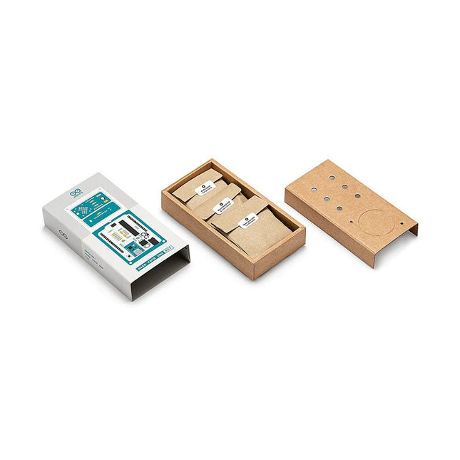
Learn the basics of electronics by assembling manually your Arduino Uno, become familiar with soldering by mounting every single component, and then unleash your creativity with the only kit that becomes a synth!
The Arduino Make-Your-Uno kit is really the best way to learn how to solder. And when you are done, the packaging allows you to build a synth and make your music.
A kit with all the components to build your very own Arduino Uno and audio synthesizer shield.
The Make-Your-Uno kit comes with a complete set of instructions in a dedicated content platform. This includes video material, a 3D interactive viewer for following detailed instructions, and how to program your board once it is finished.
This kit contains:
Arduino Make-Your-Uno
1x Make-Your-Uno PCB
1x USB C Serial adapter Board
7x Resistors 1k Ohm
2x Resistors 10k Ohm
2x Resistors 1M Ohm
1x Diode (1N4007)
1x 16 MHz Crystal
4x Yellow LEDs
1x Green LED
1x Push-Button
1x MOSFET
1x LDO (3.3 V)
1x LDO (5 V)
3x Ceramic capacitors (22pF)
3x Electrolytic capacitors (47uF)
7x Polyester capacitors (100nF)
1x Socket for ATMega 328p
2x I/O Connectors
1x Connector header 6 pins
1x Barrel jack connector
1x ATmega 328p Microcontroller
Arduino Audio Synth
1x Audio Synth PCB
1x Resistor 100k Ohm
1x Resistor 10 Ohm
1x Audio amplifier (LM386)
1x Ceramic capacitors (47nF)
1x Electrolytic capacitors (47uF)
1x Electrolytic capacitors (220uF)
1x Polyester capacitor (100nF)
4x connectors pin header
6x potentiometer 10k Ohm with plastic knobs
Spare parts
2x Electrolytic capacitors (47uF)
2x Polyester capacitor (100nF)
2x Ceramic capacitors (22pF)
1x Push-Button
1x Yellow LEDs
1x Green LED
Mechanical parts
5x Spacers 12 mm
11x Spacers 6 mm
5x screw nuts
2x screws 12 mm
The SparkFun RP2040 mikroBUS Development Board is a low-cost, high performance platform with flexible digital interfaces featuring the Raspberry Pi Foundation's RP2040 microcontroller. Besides the Thing Plus or Feather PTH pin layout, the board also includes a microSD card slot, 16 MB (128 Mbit) flash memory, a JST single cell battery connector (with a charging circuit and fuel gauge sensor), an addressable WS2812 RGB LED, JTAG PTH pins, four (4-40 screw) mounting holes, our signature Qwiic connectors, and a mikroBUS socket. The mikroBUS standard was developed by MikroElektronika. Similar to Qwiic and MicroMod interfaces, the mikroBUS socket provides a standardized connection for add-on Click boards to be attached to a development board and is comprised of a pair of 8-pin female headers with a standardized pin configuration. The pins consist of three groups of communications pins (SPI, UART and I²C), six additional pins (PWM, Interrupt, Analog input, Reset and Chip select), and two power groups (3.3 V and 5 V). The RP2040 is supported with both C/C++ and MicroPython cross-platform development environments, including easy access to runtime debugging. It has UF2 boot and floating-point routines baked into the chip. While the chip has a large amount of internal RAM, the board includes an additional 16 MB of external QSPI flash memory to store program code. The RP2040 contains two ARM Cortex-M0+ processors (up to 133 MHz) and features: 264 kB of embedded SRAM in six banks 6 dedicated IO for SPI Flash (supporting XIP) 30 multifunction GPIO: Dedicated hardware for commonly used peripherals Programmable IO for extended peripheral support Four 12-bit ADC channels with internal temperature sensor (up to 0.5 MSa/s) USB 1.1 Host/Device functionality Features (SparkFun RP2040 mikroBUS Dev. Board) Raspberry Pi Foundation's RP2040 microcontroller 18 Multifunctional GPIO Pins Four available 12-bit ADC channels with internal temperature sensor (500kSa/s) Up to eight 2-channel PWM Up to two UARTs Up to two I²C buses Up to two SPI buses Thing Plus (or Feather) Pin Layout: 28 PTH Pins USB-C Connector: USB 1.1 Host/Device functionality 2-pin JST Connector for a LiPo Battery (not included): 500mA charging circuit 4-pin JST Qwiic Connector LEDs:
PWR - Red 3.3V power indicator
CHG - Yellow battery charging indicator
25 - Blue status/test LED (GPIO 25)
WS2812 - Addressable RGB LED (GPIO 08) Buttons: Boot Reset JTAG PTH Pins 16MB QSPI Flash Memory µSD Card Slot mikroBUS Socket Dimensions: 3.7' x 1.2' Four Mounting Holes: 4-40 screw compatible Downloads Schematic Eagle Files Board Dimensions Hookup Guide Qwiic Info Page GitHub Hardware Repository
The Sensirion SGP30 is a digital multi-pixel gas sensor that can easily integrate with air purifiers, demand-controlled ventilation, and other IoT applications. Powered by Sensirion’s CMOSens®technology, it integrates a complete sensor system on a single chip featuring a digital I2C interface, a temperature-controlled micro hotplate, and two preprocessed indoor air quality signals. As the first metal-oxide gas sensor featuring multiple sensing elements on one chip, the SGP30 provides more detailed information about air quality. Features Multi-pixel gas sensor for indoor air quality applications Outstanding long-term stability I2C interface with TVOC and CO2eq output signals Low power consumption Chip module tape and reel packaged, reflow solderable Specifications Weight: 9g Battery: Exclude Working Voltage: 3.3V/5V Output range: TVOC-0 ppb to 60000ppb / CO₂eq - 400 ppm to 60000 ppm Sampling rate: 1 Hz
The matte-black circuit board is extra thick and has subtle white markings, including an alphanumeric grid and PIN labels. The wiring pattern – that of classic breadboards – is easy to see by looking at the exposed traces on the bottom of the board.
The kit comes complete with the 'Integrated Circuit Leg' stand and 8 colour-coded thumbscrew terminal posts. Using the terminal posts and solder points, you can hook up to your 'IC' with bare wires, lugs, alligator clips, and/or solder joints. Connections to the 8 terminal posts are through the three-position strips on the PCB; each is labelled with the corresponding PIN.
Features
Anodized aluminium stand
8-32 size press-fit threaded inserts (8 pieces) pre-installed in the protoboard
All materials (including the circuit board and stand) are RoHS compliant (lead-free)
Tri lobular thread forming screws (6 pieces, black, 6-32 thread size) and spacers for mounting the stand.
Dimensions: 13.25 x 8.06 x 2.54 mm
Dimensions assembled: 13.25 x 9.9 x 4.3 cm
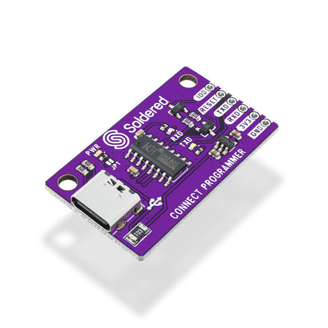
The Soldered CONNECT Programmer is designed to make programming boards based on ESP8266 and ESP32 microcontrollers extremely simple. It contains all the necessary electronics and logic, allowing programming to be done by simply plugging a USB cable into the CONNECT Programmer and connecting it to the programming header. The onboard circuitry handles timing and signal sequencing automatically, placing the ESP microcontroller into bootloader mode without the need for manual intervention.
Features
IC: CH340
Pin layout: GPIO0, RESET, RX, TX, 3V3, GND
LEDs: RX, TX, power
Interface: USB-C
Dimensions: 38 x 22 mm
Downloads
Datasheet
GitHub
This PCIe 3.0 to dual M.2 HAT enables the Raspberry Pi 5 to access two NVMe SSDs, Hailo-8/8L (M.2 key B+M only), and Google Coral AI accelerators at PCIe 3.0 speeds.
Features
Dual M.2 Slots with PCIe 3.0 Speed: Utilizes the ASMedia ASM2806 PCIe 3.0 switch chip to ensure optimal performance, overcoming the limitations of PCIe 2.0.
Stable Power Supply: Additional pogo pins provide extra power to ensure a stable high-speed connection.
Multiple Size Support: Compatible with M.2 standard sizes 2230, 2242, 2260, and 2280.
Back-mounted Design: Keeps the 40-pin GPIO free for use, allowing compatibility with other Raspberry Pi HATs.
User-friendly Design: The S-shaped FPC cable does not obstruct the microSD card slot.
Open Source Case: Seeed’s M.2 HATs are not compatible with the official Raspberry Pi case, but an adapted 3D-printable case (STP file) is provided.
Applications
Simultaneously supports AI acceleration and high-speed SSD storage
Connects dual NVMe SSDs for large storage capacity
Booting a Raspberry Pi from the SSD
Specifications
M.2 Slots
2
Max. PCIe Speed
PCIe Gen3.0
PCIe Switch Chip
ASM2806
M.2 Size Support
2280/2260/2242/2230
Max. Power Supply
5 V/3 A (max 3A: Pogo pin 2A + PCIe connector 1A)
Cable
FPC
Assembly Method
Back installation
Dimensions
87 x 55 x 10 mm
Included
1x Seeed Studio PCIe 3.0 to Dual M.2 HAT for Raspberry Pi 5
2x FPC cables (50 mm)
1x Screws & stud pack
Downloads
Wiki
A Small Basic Approach
There are many different PC programming languages available on the market. Some have beautiful names; some have easy to use development tools. Others have incredible power. They all have one thing in common: they assume that you have, or want to have, a knack for technology and difficult to read commands.
In this book we take a practical approach to programming. We assume that you simply want to write a PC program, and write it quickly. Not in a professional environment, not in order to start a new career, but for plain and simple fun... or just to get a task done.
Therefore we use Small Basic. You will have an application up and running in a matter of minutes. You will understand exactly how it works and be able to write text programs, graphical user interfaces, and advanced drivers. It is so simple; you don't even need to be an adult!
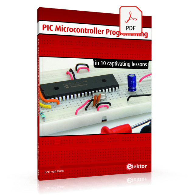
in 10 captivating lessons
Using the lessons in this book you learn how to program a microcontroller. You’ll be using JAL, a free but extremely powerful programming language for PIC microcontrollers, which enjoys great popularity in the hobby world. Starting out from scratch virtually, you slowly build up the knowledge. No previous knowledge is needed: anyone can get started with this book. Assuming you have absorbed all lessons – meaning you have actually completed all the exercises – you should be confident to write PIC microcontroller programs, as well as read and understand programs written by other people.
JAL commands
You learn the function of JAL commands such as include, pin, delay, forever loop, while loop, case, exit loop, repeat until, if then, as well as the use of functions, procedures and timer- and port interrupts.
JAL programs
You make an LED blink, build a time switch, measure a potentiometer’s wiper position, produce sounds, suppress contact bounce, and control the brightness of an LED. And of course you learn to debug, meaning: how to spot and fix errors in your programs.
Hardware
You learn to recognize various components including the PIC microcontroller, potentiometer and quartz crystal, and how to wire up a PIC microcontroller and effectively link it to your PC. A breadboard is used for the purpose, allowing you to easily modify the component arrangement for further experimenting.
The companion software with this book can be downloaded free of charge, including the JAL programming language. In addition, you may order a kit of parts so you don’t have to go shopping for the required components. Especially for a beginner, this is the easiest way to start with this unique pastime.
Having finished this book does not mean you are through with your pastime. You can get your hands dirty again, and if desired use other books packed with fun projects using the JAL programming language. More information may be found at the end of the lessons in the chapter "Done! What’s next?""
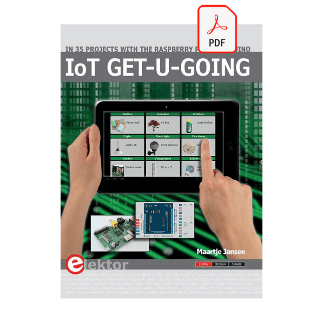
In 35 Projects with the Raspberry Pi and Arduino
The Internet of Things (IoT) is a trend with a strong technological impulse. At home, we want to do everything on our tablets, from browsing Facebook to watching TV, from operating lights to keeping an eye on the temperature.
In 35 fun projects, this book will show you how to build your own Internet of Things system. We'll cover the hardware (primarily the Raspberry Pi and Arduino) and the software that makes control via Internet possible. We employ Wi-Fi and radio links so no requirement any longer to install cabling crisscross through your home.
Assuming the projects in the book are finished, you have a complete Internet of Things system that allows you to control and view of everything in your home. For example, if there's something in the mail box or the car is securely in the garage. Also, you can switch on the lights and the alarm from your couch. The crisp explanations allow the projects to be customized with ease, for example, to turn on your coffee machine or TV remotely. The index gives easy access to creative projects that can serve as an example, enabling you to do all the connecting to the IoT independently. All project software can be downloaded free of charge from the Elektor website.
In this unique book, Raspberry Pi, Arduino and HTML webpages with stylesheets and JavaScript come together in clearly-described, easy-to-build projects. This special book is an essential part of your collection!
This book is aimed at practising engineers, students and hobbyists. It is intended as a source of reference for hardware and software associated with instrumentation and control engineering. Examples are presented from a range of industries and applications.
Throughout the book, circuit diagrams and software listings are described, typical of many measurement and control applications. The hardware and software designs may be used as a basis for application by the reader.
The book contains examples of PIC, PLC, PAC and PC programming. All code samples are available to download free of charge from the support website.
After an introductory section on control theory and modelling, the text focus is upon software for control system simulation and implementation, with appropriate reference to interfacing, electronic hardware and computing platforms.
Introduction to Control Engineering is a sourcebook of solutions for control system applications!
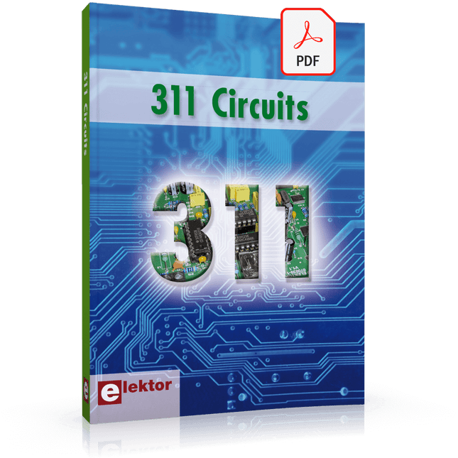
311 Circuits is the twelfth book in Elektor’s celebrated ‘300’ series. An immense source of inspiration for all electronics enthusiasts and professionals, this book deserves a place not far from the workbench.
This book contains circuits, design ideas, tips and tricks from all areas of electronics: audio & video, computers & microcontrollers, radio, hobby & modelling, home & garden, power supplies & batteries, test & measurement, software, not forgetting a section ‘miscellaneous’ for everything that doesn’t fit in one of the other categories.
311 Circuits presents complete solutions for numerous problems, as well as starting points for your own creations. 311 Circuits has been compiled from the 2009, 2010 and 2011 ‘Summer Circuits’ double editions of Elektor magazine. The book is mostly based on readers’ contributions, supplemented by circuits engineered and developed in the Elektor Labs.
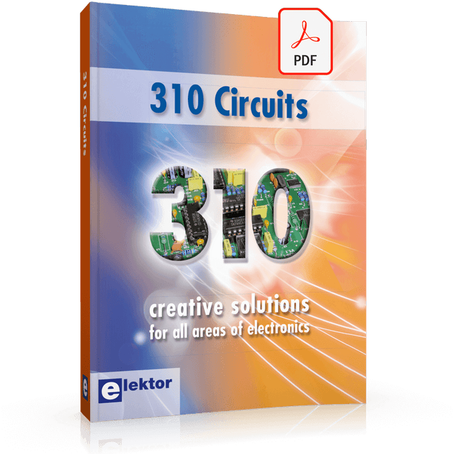
310 Circuits – is the 11th volume in Elektor’s renowned ‘Three Hundred’ series. 310 circuits, tips and design ideas in one book form a treasure trove for every area of electronics: audio and video, hobby and modelling, RF techniques, home and garden, test and measurement, microcontrollers, computer hardware and software, power supplies and chargers – plus of course everything else that does not seem to belong in any of these categories.
310 Circuits – contains many complete solutions as well as useful starting points for your own projects. Both categories and anything in between represent a veritable fountain of inspiration for cultivating your own ideas and learning about electronics.
310 Circuits – is a compilation of articles from ‘Summer Circuits’ editions for the years 2006, 2007 and 2008. ‘Summer Circuits’ covers the publication months July and August of Elektor magazine.
310 Circuits – is a must-have book for every creative electronics enthusiast, be it professional, enthusiast or student.
310 Circuits – for the first time has a section exclusively on robots and robotics.
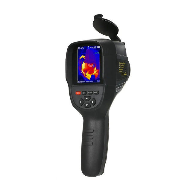
The Hti HT-18+ is a professional thermal imaging camera designed for precise temperature measurements and real-time thermal imaging. It has an impressive infrared resolution of 256 x 192 pixels at a frame rate of 25 Hz, resulting in clear and detailed thermal images. The temperature measurement range extends from −20°C to +550°C, with a measurement accuracy of ±2°C or ±2%.
The camera is equipped with a 3.2-inch color display for easy viewing of thermal images. It offers five different color palettes – rainbow, iron red, cold color, black and white and white and black – to adapt the display to different requirements. It also has a built-in memory of 4 GB for storing images and videos in JPG or MP4 format, which can be transferred to a computer via a USB connection.
Specifications
Infrared resolution
256 x 192
Infrared response band
8 to 14 μm
Cell size
12 μm
NETD
≤50 mK @ 25°C, @F/1.1
Lens focal length
3.2 mm
IFOV
3.75 mrad
Field angle
56° x 42°
Focus mode
Free focus
Temperature measurement range
−20°C~550°C (−4~1022°F)
Measurement accuracy
−15°C to 550°C (±2°C or ±2%)−20°C to −15°C (±4°C)
Temperature measurement resolution
0.1°C
Temperature measurement mode
Center point/hot and cold spot tracking
Color palette
Rainbow, iron oxide red, cold color, black & white, white & black
Emissivity setting
Adjustable from 0.01 to 1.00
Thermal imaging frame rate
≤25 Hz
Visible light resolution
640 x 480
Display size
3.2-inch (240 x 320)
Image display mode
Infrared/visible light/dual light fusion
Device storage
Built-in 4 GB eMMC (user available storage space is about 3 GB
Storage Image/Video Format
JPG/MP4
Image/video export method
USB connection to computer export
Image analysis function
Support offline analysis on PC
Battery Type
Dedicated removable rechargeable Lithium battery
Battery capacity
2200 mAh
Working time
2 to 3 hours
Power interface
Micro USB
Power configuration
5 minutes, 20 minutes, no automatic shutdown
Working temperature
−10°C to +50°C
Relative humidity
10% to 85% RH (non-condensing)
Menu languages
English, German, Italian, Chinese
Dimensions
90 x 105 x 223 mm
Weight
389 g
Included
1x Hti HT-18+ Thermal Imaging Camera
1x USB cable
1x Manual
Downloads
Manual
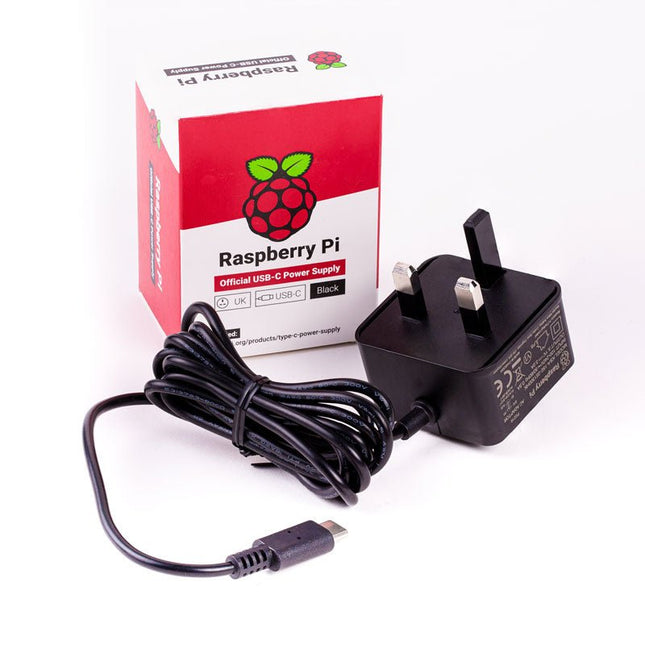
The Raspberry Pi USB-C power supply is designed specifically to power the latest Raspberry Pi 4 Model B computers.
The power supply features a USB-C cable and is available in four different models to suit different international power sockets, and in two colors.
Specifications
Output
Output voltage
+5.1 V DC
Minimum load current
0 A
Nominal load current
3.0 A
Maximum power
15.3 W
Load regulation
±5 %
Line regulation
±2 %
Ripple & noise
120 mVp-p
Rise time
100 ms maximum to regulation limits for DC outputs
Turn-on delay
3000 ms maximum at nominal input AC voltage and full load
Protection
Short circuit protectionOvercurrent protectionOver temperature protection
Efficiency
81% minimum (output current from 100%, 75%, 50%, 25%)72% minimum at 10% load
Output cable
1.5 m 18AWG
Output connector
USB Type-C
Input
Voltage range
100-240 VAC (rated)96-264 VAC (operating)
Frequency
50/60 Hz ±3 Hz
Current
0.5 A maximum
Power consumption (no load)
0.075 W maximum
Inrush current
No damage shall occur, and the input fuse shall not blow
Operating ambient temperature
0-40°C
If you are looking for an easy way to get started with soldering or simply want to make a small portable gadget, this set is a great opportunity. "LED cube" is an educational set for learning the soldering skill, with which you get a small electronic game at the end. After you turn on and shake this board, certain leds will light up randomly and symbolize the number, as if a real die had been thrown.
It is based on the Attiny404 microcontroller, programmed in Arduino, and there is a battery on the back which makes this gadget portable. There is also a keychain so you can always carry your new game with you! Soldering is easy according to the markings on the board.
Included
1x PCB
1x ATtiny404 microcontroller
7x LEDs
7x Resistors (330 ohm)
1x Resistor (10 kohm)
1x Battery holder
1x CR2032 battery
1x Switch
1x Vibration sensor SW-18020P
1x Keychain ring
The Challenger RP2040 NFC is a small embedded computer, equipped with an advanced on-board NFC controller (NXP PN7150), in the popular Adafruit Feather form factor. It is based on an RP2040 microcontroller chip from the Raspberry Pi Foundation which is a dual-core Cortex-M0 that can run on a clock up to 133 MHz.
NFC
The PN7150 is a full featured NFC controller solution with integrated firmware and NCI interface designed for contactless communication at 13.56 MHz. It is fully compatible with NFC forum requirements and is greatly designed based on learnings from previous NXP NFC device generation. It is the ideal solution for rapidly integrating NFC technology in any application, especially small embedded systems reducing Bill of Material (BOM).
The integrated design with full NFC forum compliancy gives the user all the following features:
Embedded NFC firmware providing all NFC protocols as pre-integrated feature.
Direct connection to the main host or microcontroller, by I²C-bus physical and NCI protocol.
Ultra-low power consumption in polling loop mode.
Highly efficient integrated power management unit (PMU) allowing direct supply from a battery.
Specifications
Microcontroller
RP2040 from Raspberry Pi (133 MHz dual-core Cortex-M0)
SPI
One SPI channels configured
I²C
Two I²C channel configured (dedicated I²C for the PN7150)
UART
One UART channel configured
Analog inputs
4 analog input channels
NFC module
PN7150 from NXP
Flash memory
8 MB, 133 MHz
SRAM memory
264 KB (divided into 6 banks)
USB 2.0 controller
Up to 12 MBit/s full speed (integrated USB 1.1 PHY)
JST Battery connector
2.0 mm pitch
On board LiPo charger
450 mA standard charge current
Dimensions
51 x 23 x 3,2 mm
Weight
9 g
Note: Antenna is not included.
Downloads
Datasheet
Quick start example
The board's main processor is a low-power Arm® Cortex®-M0 32-bit SAMD21. The WiFi and Bluetooth® connectivity is performed with a module from u-blox, the NINA-W10, a low-power chipset operating in the 2.4GHz range. On top of that, secure communication is ensured through the Microchip® ECC608 crypto chip. Besides that, you can find a 6 axis IMU, which makes this board perfect for simple vibration alarm systems, pedometers, the relative positioning of robots, etc. WiFi and Arduino IoT Cloud You can get your board to connect to any kind of existing WiFi network, or use it to create your own Arduino Access Point. The specific set of examples we provide for the Nano 33 IoT can be consulted at the WiFiNINA library reference page. It is also possible to connect your board to different Cloud services, Arduino's own among others. Here are some examples of how to get the Arduino boards to connect to:
Arduino's own IoT Cloud: Arduino's IoT Cloud is a simple and fast way to ensure secure communication for all of your connected Things. Check it out here.
Blynk: a simple project from our community connecting to Blynk to operate your board from a phone with little code.
IFTTT: see an in-depth case of building a smart plug connected to IFTTT.
AWS IoT Core: we made this example on how to connect to Amazon Web Services.
Azure: visit this GitHub repository explaining how to connect a temperature sensor to Azure's Cloud.
Firebase: you want to connect to Google's Firebase, this Arduino library will show you how. Microcontroller SAMD21 Cortex®-M0+ 32bit low power ARM MCU Radio Module u-blox NINA-W102 Secure Element ATECC608A Operating Voltage 3.3 V Input Voltage 21 V Digital I/O Pins 14 PWM Pins 11 DC Current per I/O Pin 7 mA Analog Input Pins 8 Analog Output Pins 1 External Interrupts all digital pins UART 1 SPI 1 I2C 1 Flash Memory 256 KB SRAM 32 KB EEPROM none Clock Speed 48 MHz LED_Builtin 13 USB Native in the SAMD21 Processor IMU LSM6DS3 Length 45 mm Width 18 mm Weight 5 g
Pico Breakout Garden Base sits underneath your Pico and lets you connect up to six of our extensive selection of Pimoroni breakouts to it. Whether it's environmental sensors so you can keep track of the temperature and humidity in your office, a whole host of little screens for important notifications and readouts, and, of course, LEDs. Scroll down for a list of breakouts that are currently compatible with our C++/MicroPython libraries!As well as a labelled landing area for your Pico, there's also a full set of broken out Pico connections, in case you need to attach even more sensors, wires, and circuitry. We've thrown in some rubber feet to keep the base nice and stable and to stop it from scratching your desk, or there are M2.5 mounting holes at the corners so that you can bolt it onto a solid surface if you prefer.The six sturdy black slots are edge connectors that connect the breakouts to the pins on your Pico. There's two slots for SPI breakouts, and four slots for I²C breakouts. Because I²C is a bus, you can use multiple I²C devices at the same time, providing they don't have the same I²C address (we've made sure that all of our breakouts have different addresses, and we print them on the back of the breakouts so they're easy to find).As well as being a handy way to add functionality to your Pico, Breakout Garden is also very useful for prototyping projects without the need for complicated wiring, soldering, or breadboards, and you can grow or change up your setup at any time.Features
Six sturdy edge-connector slots for breakouts
4x I²C slots (5 pins)
2x SPI slot (7 pins)
Landing area with female headers for Raspberry Pi Pico
0.1” pitch, 5 or 7 pin connectors
Broken-out pins
Reverse polarity protection (built into breakouts)
99% assembled – just need to stick on the feet!
Compatible with Raspberry Pi Pico
Master FPGA programming with the Red Pitaya Academy Pro Box. Learn Verilog and build a real-time audio processing system using Red Pitaya – with a full online course and hands-on project materials.
The Academy Pro Box "Learn FPGA Programming with Verilog" is a complete learning solution for students, engineers and developers looking to gain hands-on experience with FPGA programming in Verilog. Combining theory with practice, the programme integrates a well-established Udemy course on Verilog fundamentals with nine exclusive practical modules developed by Elektor & Red Pitaya, designed specifically for the Red Pitaya STEMlab platform.
Participants work with real hardware – delivered as part of the box – including the Red Pitaya STEMlab 125-14 Starter Kit and essential electronic components, enabling them to apply their knowledge immediately through real-world test setups. This combination of guided theory and structured experimentation ensures not only a strong understanding of FPGA principles, but also the ability to implement and verify designs independently.
The box is aimed at professionals and advanced learners who want to go beyond simulation and gain practical skills in digital design. By the end of the programme, participants will have completed working FPGA projects, using industry-relevant tools and workflows – making this a valuable resource for academic & career development and technical innovation.
What you’ll learn?
Fundamentals of FPGA and Verilog Programming
How to simulate, synthesize & implement digital circuits
How to interface audio hardware with your FPGA
Real-time Digital Signal Processing (DSP) techniques
How to build, test, and customize audio filters
Perfect for
Professionals looking to level up their skills in Digital System Design
Designers aiming to accelerate time-to-market for their applications
Engineers pushing the boundaries of technological innovation
Support when you need it
In-depth troubleshooting in the course
Community forums & Red Pitaya documentation
Udemy Q&A and hardware support email
What's inside the Box (Course)?
Red Pitaya STEMlab 125-14 Starter Kit (valued at €550)
1x STEMlab 125-14 board
1x USB power supply (EU, UK & US)
1x microSD card (16 GB) with pre-installed OS
1x Ethernet cable
Extra: 2x Oscilloscope Probes
Extra: 2x SMA to BNC adapters
Microphone & speaker set with cables
Step-by-step project guide
Downloadable code templates and schematics
Lifetime access to a complete, self-paced Udemy course on Verilog
Learning Material (of this Box/Course)
9 Practical Modules with Red Pitaya
▶ Click here to open
Introduction
Setting Up the Vivado Development Environment
Project Setup & Vivado Integration
Synthesis, Implementation & Bitstream Generation
FPGA Image Overview
First FPGA Projects – LEDs
Full Audio Pass-Through Module
5 kHz Low-Pass Filter (4-Pole Cascade)
Real-Time Microphone Input → Speaker Output
Verilog Course with 28 Lessons on Udemy
▶ Click here to open
Installing Vivado
Vivado Design Flow Part 1
Vivado Design Flow Part 2
Commonly Asked Question’s from previous Module
Fundamentals of Verilog
Commonly Asked Question’s from previous Module
Modeling Styles
Assignment Operators in Verilog
FAQ
Behavioral Modeling Style
Commonly Asked Question's from previous Module
Gate Level Modeling Style
Switch level Modeling Style
Structural Modeling Style
Schematic based Design Entry with IP integrator and Xilinx IP's
Memories
Commonly Asked Question's from previous Module
Finite State Machines
Commonly Asked Question's from previous Module
Writing Testbenches
Hardware Debugging with Vivado Required Hardware
v File I/0
Projects
RTL for Synthesis
FPGA Architecture Fundamentals
Commonly Asked Question's from previous Module
Interview Preparations
Next Step
What is Elektor Academy Pro?
Elektor Academy Pro delivers specialized learning solutions designed for professionals, engineering teams, and technical experts in the electronics and embedded systems industry. It enables individuals and organizations to expand their practical knowledge, enhance their skills, and stay ahead of the curve through high-quality resources and hands-on training tools.
From real-world projects and expert-led courses to in-depth technical insights, Elektor empowers engineers to tackle today’s electronics and embedded systems challenges. Our educational offerings include Academy Books, Pro Boxes, Webinars, Conferences, and industry-focused B2B magazines – all created with professional development in mind.
Whether you're an engineer, R&D specialist, or technical decision-maker, Elektor Academy Pro bridges the gap between theory and practice, helping you master emerging technologies and drive innovation within your organization.
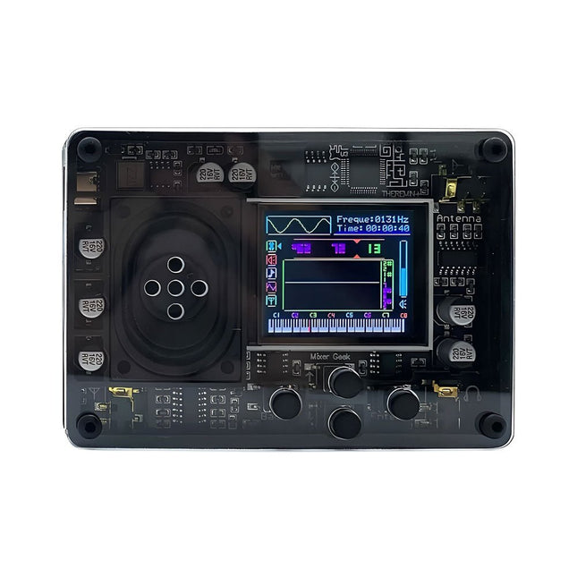
The Mixer Geek Theremin+ is a fun and innovative electronic musical instrument inspired by the classic Theremin. Unlike traditional instruments, the Theremin+ is played without physical contact, using hand movements in the air to control pitch and volume.
The Theremin+ offers an exciting and hands-on way to explore music and sound experimentation.
Features
Ready to use out of the box
Equipped with a loudspeaker and full-color screen
Intuitive button-based navigation and confirmation
Choose from over 70 tones
Multiple customizable function settings
Displays waveform, time, frequency, volume, and corresponding piano pitch (display can be turned off)
Powered via USB-C port; compatible with power banks
Compact design with removable telescopic antenna for easy storage
Connects to headphones, external speakers, or recording devices
Dimensions: 98 x 70 x 18 mm
Included
1x Theremin+ Musical Instrument
2x Antennas
1x USB-C cable
The JLINK V9 USB-JTAG Arm Emulator/Debugger is a high-performance and reliable tool for programming and debugging ARM Cortex-M, Cortex-A/R, and other supported microcontrollers via JTAG and SWD interfaces.
Features
Universal Compatibility: Supports a wide range of ARM-based MCUs and cores including Cortex-M0, M3, M4, M7, A5, A7, A9, and R4.
High-Speed Performance: Fast data throughput for both flash programming and real-time debugging with minimal latency.
Multi-Interface Support: Offers both JTAG and SWD modes, enabling flexible use in different development environments.
Plug & Play via USB: Easy connection to your PC with USB 2.0 interface; no external power supply required.
Robust Software Support: Fully compatible with SEGGER J-Link software tools and supported by major IDEs including Keil MDK, IAR EWARM, SEGGER Embedded Studio, and others.
Included
1x JLINK V9 USB-JTAG Arm Emulator/Debugger
1x USB Cable
1x Connector Cable
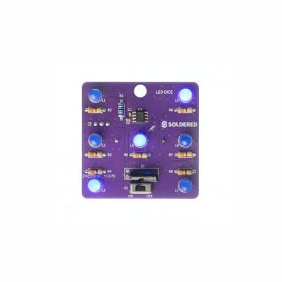
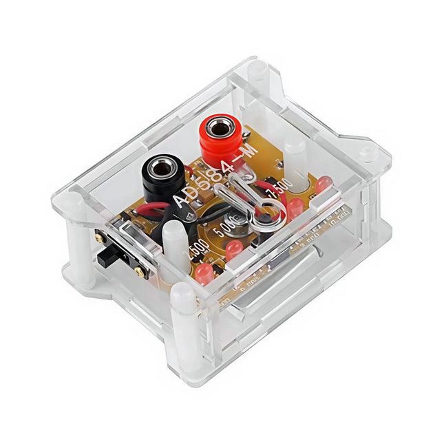
The AD584 4-ch Voltage Reference Module is designed to provide stable and accurate reference voltages of 2.5 V, 5 V, 7.5 V, and 10 V. It incorporates the AD584 integrated circuit, known for its high accuracy and stability.
Features
Multiple Output Voltages: The module can output four different reference voltages (2.5 V, 5 V, 7.5 V, and 10 V) accessible through a single port.
Microcontroller-based Switching: An onboard microcontroller facilitates switching between the four voltage outputs, with LED indicators displaying the active selection.
User-Friendly Operation: A single button allows for easy cycling through the available reference voltages.
Transparent Housing: The module is encased in a transparent housing, offering protection while allowing users to view the internal components.
Power Supply Options: It can be powered via a built-in lithium battery (not included) or through a 5 V DC input. A charging indicator provides status updates during charging.
Output Interface: Equipped with 4mm banana sockets for secure and reliable connections.
Included
1x AD584 4-ch Voltage Reference Module with Housing
Downloads
Datasheet