Bestsellers
-

Generic Ultrasonic Distance Sensor (ME007-ULA V1)
This ultrasonic distance sensor (ME007-ULA V1) offers high performance with a robust, waterproof probe. Operating on the principle of ultrasonic echo ranging, the sensor determines the distance to a target by measuring the time elapsed between sending a pulse and receiving the echo. Its non-contact design allows it to detect a wide range of materials, including transparent or non-ferrous objects, metals, non-metals, liquids, solids, and powders. Specifications Detecting Distance 27~800 cm Output Interface RS232, Voltage Analog Operating Voltage 5-12 V Average Current <10 mA Operating Temperature −15~60°C Dimensions 60 x 43 x 31 mm
€ 29,95
Members € 26,96
-
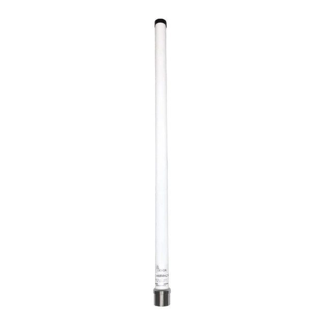
OPA Design ISM Band Outdoor Antenna (868 MHz)
This fiberglass outdoor antenna is optimized for receiving signals in the 868 MHz ISM band, supporting technologies such as Sigfox, LoRa, Mesh Networks, and Helium. The antenna consists of a half-wave dipole with 4.4 dBi gain, encapsulated inside a fiberglass radome with an aluminum mounting base. Specifications Frequency 868-870 MHz Antenna type Dipole 1/2 wave Connector N female Installation type Mast Diam 35-60 mm (mounting bracket included) Gain 4.4 dBi SWR ≤1.5 Type of Polarization Vertical Maximum power 10 W Impedance 50 Ohms Dimensions 52.5 cm Tube diameter 26 mm Base antenna 32 mm Operating temperature −30°C to +60°C Included ISM Band Antenna (868 Mhz) Mast bracket (for installation on a 35 to 60 mm diameter mast)
€ 69,95€ 54,95
Members identical
-

Velleman Whadda Shaking Dice
When playing a board game, do you find it annoying when you push away all the pawns with the dice? Or when friends try to cheat by manipulating the dice? With this soldering kit, this is a thing of the past. Instead of pressing a button, you activate this microprocessor-controlled dice by shaking. The 7 flashing LEDs run out slowly and the final combination is displayed flashing. The kit works with one CR2025 or one CR2032 button cell (not included). Downloads Manual
€ 14,95
Members € 13,46
-

Velleman Whadda E-12 Series Resistor Set (610 pcs)
The Whadda E12 is a high-quality carbon film resistor set comprising 610 pieces, with 10 pieces for each of the 61 standard E12 series values ranging from 10 Ω to 1 MΩ. Each resistor has a power rating of 0.25 W, a tolerance of 5%, and can operate within a temperature range of -55°C to 155°C. The maximum operating voltage is 250 V. These resistors are suitable for applications in TVs, audio and video equipment, telephone receivers, communication systems, instrumentation, and home appliances.
€ 11,95
Members € 10,76
-
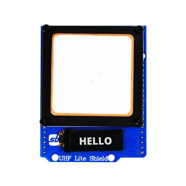
SB Components Ardi UHF Shield for Arduino Uno (EU/UK)
Designed with cutting-edge technology, this shield brings the power of Ultra High Frequency (UHF) RFID to your fingertips. With the Ardi UHF Shield, you can effortlessly read up to an impressive 50 tags per second, allowing for fast and efficient data collection. The shield features an onboard UHF antenna, ensuring reliable and accurate tag detection even in challenging environments. Equipped with a high-performance 0.91" OLED display, the Ardi UHF Shield provides clear and concise visual feedback, making it easy to monitor and interact with the RFID readings. Whether you're tracking inventory, managing access control, or implementing a smart attendance system, this shield has you covered. With a remarkable 1-meter reading distance, the Ardi UHF Shield offers an extended range for capturing RFID data. Say goodbye to the limitations of proximity-based RFID systems and embrace the flexibility and convenience of a wider reading range. The shield provides read-write capabilities, allowing you to not only retrieve information from RFID tags but also update or modify data as needed. This versatility opens up a world of possibilities for advanced applications and custom solutions. Features Onboard High-performance UHF RFID reader module 24 hours x 365 days’ work normally 0.91” OLED display for visual interaction with shield Multi-tone Buzzer onboard for Audio alerts Shield compatible with both 3.3 V and 5 V MCU Mounts directly onto ArdiPi, Ardi32 or other Arduino compatible boards Specifications OLED resolution 128x32 pixels I²C Interface for OLED UHF Frequency Range (EU/UK): 865.1-867.9 MHz UHF Module Type: Read/Write Protocols Supported: EPCglobal UHF Class 1 Gen 2 / ISO 18000-6C Reading Distance: 1 meters Can identify over 50 tags simultaneously Communication interface: TTL UART Interface for UHF Communication baud rate: 115200 bps (default and recommend) – 38400 bps Operation current: 180 mA @ 3.5 V (26 dBm Output, 25°C), 110 mA @ 3.5 V (18 dBm Output, 25°C) Working humidity <95% (+25°C) Heat-dissipating method Air cooling(no need out install cooling fin) Tags storage capacity: 200 pcs tags @ 96 bit EPC Output power: 18-26 dBm Output power accuracy: +/-1 dB Tags RSSI support
€ 129,95€ 99,95
Members € 89,96
-
€ 10,95
Members € 9,86
-
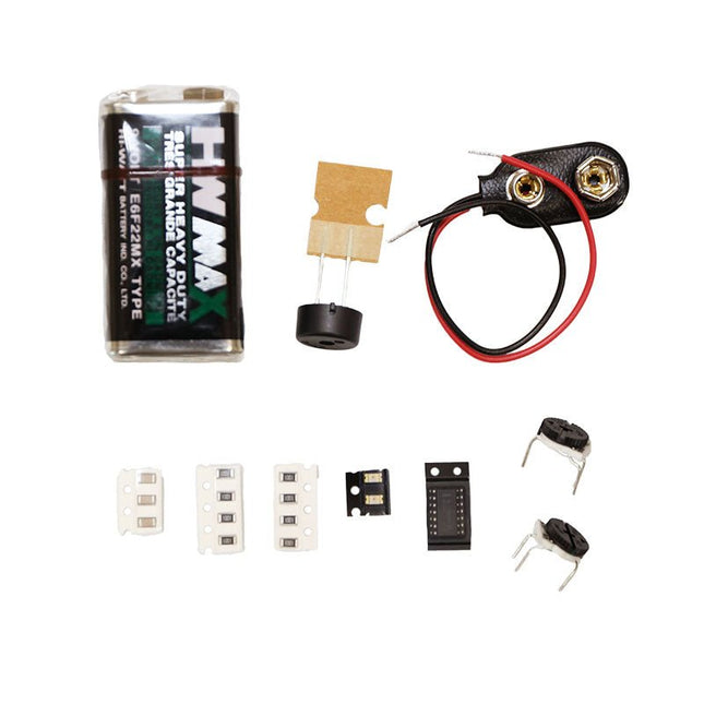
Voltera Voltera Punk Console Component Kit
The Punk Console circuit is an advanced tutorial to get you familiar with the V-One Drill attachment. Learn how to create a double sided board and turn the knobs to create music! The kit contains: 2x Green LEDs 8x 1k Resistors 3x 0.01uF Capacitor 2x 500K Trimpots 1x 556 Timer 1x Piezo Buzzer 1x 9 V Battery 1x 9 V Battery Connector Rivets and a V-One Drill are required.
€ 14,95
Members € 13,46
-

SparkFun SparkFun Qwiic IR Array MLX90640 Breakout
The MLX90640 SparkFun IR Array Breakout features a 32×24 array of thermopile sensors generating, in essence, a low resolution thermal imaging camera. With this breakout you can observe surface temperatures from a decent distance away with an accuracy of ±1.5°C (best case). This board communicates via I²C using the Qwiic system developed by Sparkfun, which makes it easier to operate the breakout. However, there are still 0.1'-spaced pins in case you favour using a breadboard. The SparkFun Qwiic connect system is an ecosystem of I²C sensors, actuators, shields and cables that make prototyping faster and helps you avoid errors. All Qwiic-enabled boards use a common 1 mm pitch, 4-pin JST connector. This reduces the amount of required PCB space, and polarized connections help you connect everything correctly. This specific IR Array Breakout provides a 110°×75° field of view with a temperature measurement range of -40~300°C. The MLX90640 IR Array has pull up resistors attached to the I²C bus; both can be removed by cutting the traces on the corresponding jumpers on the back of the board. Please be aware that the MLX90640 requires complex calculations by the host platform so a regular Arduino Uno (or equivalent) doesn't have enough RAM or flash to complete the complex computations required to turn the raw pixel data into temperature data. You will need a microcontroller with 20,000 bytes or more of RAM.
€ 109,95€ 79,95
Members identical
-

Elektor Digital Linux PC-based Measurement Electronics (E-book)
This book is intended as a highly-practical guide for Hobbyists, Engineers and Scientists wishing to build measurement and control systems to be controlled by a local or remote Personal Computer running the Linux operating system. Both hardware and software aspects of designing typical embedded systems are covered in detail with schematics, code listings and full descriptions. Numerous examples have been designed to show clearly how straightforward it can be to create the interfaces between digital and analog electronics, with programming techniques for creating control software for both local and remote systems. Hardware developers will appreciate the variety of circuits, including a novel, low cost modulated wireless link and will discover how using Matlab® overcomes the need for specialist programming skills. Software developers will appreciate how a better understanding of circuits plus the freedom offered by Linux to directly control at the register level enables them to optimize related programs. There is no need to buy special equipment or expensive software tools in order to create embedded projects covered in this book. You can build such quality systems quickly using popular low-cost electronic components and free distributed or low-cost software tools. Some knowledge of basic electronics plus the very basics of C programming only is required. Many projects in this book are developed using Matlab® being a very popular worldwide computational tool for research in engineering and science. The book provides a detailed description of how to combine the power of Matlab® with practical electronics. With an emphasis on learning by doing, readers are encouraged by examples to program with ease; the book provides clear guidelines as to the appropriate programming techniques “on the fly”. Complete and well-documented source code is provided for all projects. If you want to learn how to quickly build Linux-based applications able to collect, process and display data on a PC from various analog and digital sensors, how to control circuitry attached to a computer, then even how to pass data via a network or control your embedded system wirelessly and more – then this is the book for you! Features of this Book Use the power, flexibility and control offered only by a Linux operating system on a PC. Use a free, distributed downloadable GNU C compiler Use (optional) a low-cost Student Version of Matlab®. Use low-cost electronic sub-assemblies for projects. Improve your skills in electronics, programming, networking and wireless design. A full chapter is dedicated to controlling your sound card for audio input and output purposes. Program sound using OSS and ALSA. Learn how to combine electronic circuits, software, networks and wireless technologies in the complete embedded system.
€ 29,95
Members € 23,96
-

Elektor Digital Internet of Things (E-book)
The Internet of Things (IoT) is a new concept in intelligent automation and intelligent monitoring using the Internet as the communications medium. The “Things” in IoT usually refer to devices that have unique identifiers and are connected to the Internet to exchange information with each other. Such devices usually have sensors and/or actuators that can be used to collect data about their environments and to monitor and control their environments. The collected data can be processed locally or it can be sent to centralized servers or to the cloud for remote storage and processing. For example, a small device at the size of a matchbox can be used to collect data about the temperature, relative humidity and the atmospheric pressure. This data can be sent and stored in the cloud. Anyone with a mobile device can then access and monitor this data at any time and from anywhere on Earth provided there is Internet connectivity. In addition, users can for example, adjust the central heating remotely using their mobile devices and accessing the cloud. This book is written for students, for practising engineers and for hobbyists who want to learn more about the building blocks of an IoT system and also learn how to setup an IoT system using these blocks. Chapter 1 is an introduction to the IoT systems. In Chapter 2, the basic concepts and possible IoT architectures are discussed. The important parts of any IoT system are the sensors and actuators and they are described briefly in Chapter 3. The devices in an IoT system usually communicate with each other and the important aspect of IoT communication is covered in Chapter 4. Chapter 5 proceeds with the features of some of the commonly used development kits. One of these, the Clicker 2 for PIC18FJ manufactured by mikroElektronika, can be used as a processor in IoT systems and its features are described in detail in Chapter 6. A popular microcontroller C language, mikroC Pro for PIC gets introduced in Chapter 7. Chapter 8 covers the use of a click board with the Clicker 2 for PIC18FJ development kit. Similarly, the use of a sensor click board is described as a project in Chapter 9, and an actuator board in Chapter 10. Chapters 11 and 12 cover Bluetooth and Wi-Fi technologies in microcontroller based systems, and the remaining chapters of the book demo the creation of a simple Wi-Fi based IoT system with cloud-based data storage. This book has been written with the assumption that the reader has taken a course on digital logic design and has been exposed to writing programs using at least one high-level programming language. Knowledge of the C programming language will be very useful. Also, familiarity with at least one member of the PIC series of microcontrollers (e.g. PIC16 or PIC18) will be an advantage. The knowledge of assembly language programming is not required because all the projects in the book are based on using the C language. If you are a total beginner in programming you can still access the e-book, but first you are advised to study introductory books on microcontrollers.
€ 34,95
Members € 27,96
-
Elektor Digital Elektor September/October 2020 (PDF)
Elektor Magazine EN September/October 2020 (PDF)
€ 7,50
-
Elektor Digital Elektor July/August 2020 (PDF)
Elektor Magazine EN July/August 2020 (PDF)
€ 7,50
-

Velleman Whadda Flashing LED Sweethearts
Valentine's Hearts, 28 blinking LEDs, romantic LED lighting Valentine's Hearts – 28 blinking LEDs for a romantic atmosphere. The perfect Valentine's gift to express your love. Battery-powered and portable, ideal for Valentine's Day. Downloads Manual
€ 11,95
Members € 10,76
-
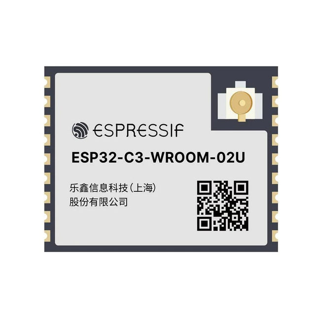
Espressif ESP32-C3-WROOM-02U-N4
ESP32-C3-WROOM-02U is a general-purpose Wi-Fi and Bluetooth LE module. The rich set of peripherals and high performance make the module an ideal choice for smart homes, industrial automation, health care, consumer electronics, etc. ESP32-C3-WROOM-02U features an external SPI flash and comes with a connector for an external antenna. ESP32-C3-WROOM-02U has an operating ambient temperature option of –40∼85°C, embedded with the ESP32-C3 chip. ESP32-C3 has a 32-bit RISC-V single-core processor. It integrates a rich set of peripherals, ranging from UART, I²C, I²S, remote control peripheral, LED PWM controller, general DMA controller, TWAI controller, USB Serial/JTAG controller, temperature sensor, ADC, etc. It also includes SPI, Dual SPI and Quad SPI interfaces. Features Flash: 4 MB (Quad SPI) Dimensions: 18.0 x 20.0 x 3.2 mm Downloads Datasheet
€ 7,95
Members € 7,16
-
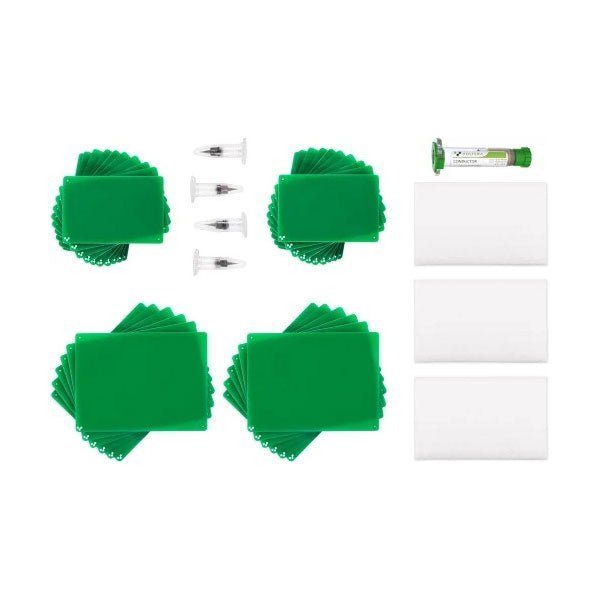
Voltera Voltera Advanced Bundle
Kit Contents 1x Conductor 2 Ink Cartridge 1x Nozzles - 225 micron (pack of 4) 1x Burnishing Pads (pack of 3) 2x 2'x3' Substrates (pack of 10) 2x 3'x4' Substrates (pack of 6)
€ 199,95€ 179,95
Members identical
-

Arduino Arduino Pro Nicla Sense ME
The Nicla Sense ME is a tiny, low-power tool that sets a new standard for intelligent sensing solutions. With the simplicity of integration and scalability of the Arduino ecosystem, the board combines four state-of-the-art sensors from Bosch Sensortec: BHI260AP motion sensor system with integrated AI BMM150 magnetometer BMP390 pressure sensor BME688 4-in-1 gas sensor with AI and integrated high-linearity, as well as high-accuracy pressure, humidity and temperature sensors. The Arduino Nicla Sense ME is the smallest Arduino form factor yet, with a range of industrial grade sensors packed into a tiny footprint. Measure process parameters such as temperature, humidity and movement. Featuring a 9-axis inertial measurement unit and the possibility for Bluetooth Low Energy connectivity, it can help you to create your next Bluetooth Low Energy enabled project. Make your own industrial grade wireless sensing network with the onboard BHI260AP, BMP390, BMM150 and BME688 Bosch sensors. Features Tiny size, packed with features Low power consumption Add sensing capabilities to existing projects When battery-powered, becomes a complete standalone board Powerful processor, capable of hosting intelligence on the Edge Measures motion and environmental parameters Robust hardware including industrial-grade sensors with embedded AI BLE connectivity maximizes compatibility with professional and consumer equipment 24/7 always-on sensor data processing at ultra-low power consumption Specifications BHI260AP – Self-learning AI smart sensor with integrated accelerometer and gyroscope BMP390 – Digital pressure sensor BMM150 – Geomagnetic sensor BME688 – Digital low power gas, pressure, temperature & humidity sensor with AI Microcontroller 64 MHz ARM Cortex-M4 (nRF52832) Sensors I/O Castellated pins with the following features: 1x I²C bus (with ext. ESLOV connector) 1x Serial port 1x SPI 2x ADC, programmable I/O voltage from 1.8-3.3 V Connectivity Bluetooth 4.2 Power Micro USB (USB-B), Pin Header, 3.7 V Li-po battery with Integrated battery charger Memory 512 KB Flash / 64 KB RAM 2 MB SPI Flash for storage 2 MB QSPI dedicated for BHI260AP Interface USB interface with debug functionality Dimensions 22.86 x 22.86 mm Weight 2 g Downloads Datasheet
€ 84,95€ 69,95
Members identical
-
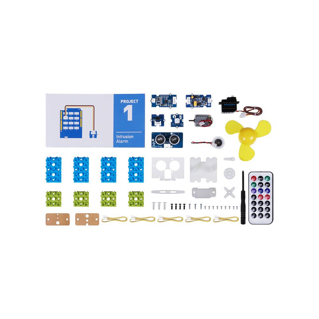
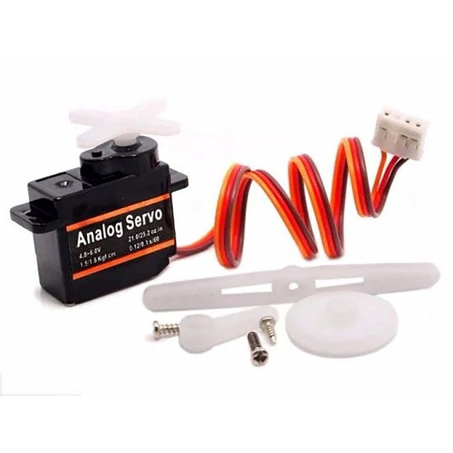
Seeed Studio Seeed Studio Grove Beginner Kit for Arduino (Education Add-on Pack)
This is an add-on kit for the Seeed Studio Grove Beginner Kit for Arduino. Applications Suitable for Arduino beginners Suitable for infrared control and motion detect Suitable for getting started with open-source hardware and Arduino coding Included 1x Grove Water Atomization 1x Grove Mini Fan 1x Grove Servo 1x Grove Ultrasonic Distance Sensor 1x Grove Infrared Receiver 1x Grove Mini PIR Motion Sensor 1x Grove Green Wrapper 1x Grove Blue Wrapper 5x Grove Cable 1x Infrared Remote Control Key 1x Ultrasonic Sensor Bracket Set 1x Motor Bracket Set 1x Servo Base
€ 52,95€ 39,95
Members identical
-

SparkFun SparkFun DLI Kit
Reinforcing its commitment to widening the accessibility to and innovation in the area of deep learning, NVIDIA has created a free, self-paced, online Deep Learning Institute (DLI) course, “Getting Started on AI with Jetson Nano.” The course's goal is to build foundational skills to enable anyone to get creative with the Jetson Developer Kit. Please be aware that this kit is for those who already own a Jetson Nano Developer Kit and want to join the DLI Course. A Jetson Nano is not included in this kit. Included in this kit is everything you will need to get started in the “Getting Started on AI with Jetson Nano” (except for a Jetson Nano, of course), and you will learn how to Set up your Jetson Nano and camera Collect image data for classification models Annotate image data for regression models Train a neural network on your data to create your own models Run inference on the Jetson Nano with the models you create The NVIDIA Deep Learning Institute offers hands-on training in AI and accelerated computing to solve real-world problems. Developers, data scientists, researchers, and students can get practical experience powered by GPUs in the cloud and earn a competency certificate to support professional growth. They offer self-paced, online training for individuals, instructor-led workshops for teams, and downloadable course materials for university educators. Included 32 GB microSD Card Logitech C270 Webcam Power Supply 5 V, 4 A USB Cable - microB (Reversible) 2-Pin Jumper Please note: Jetson Nano Developer Kit not included.
€ 79,95€ 49,95
Members identical
-

IoTize IoTize TapNLink WiFi, BLE, NFC
TapNLink modules provide wireless interfaces for linking electronic systems to mobile devices and the Cloud. TapNLink connects directly to the target system's microcontroller. It integrates into and is powered by the target system. All TapNLink products are easily configured to control access by different types of users to data in the target system. TapNLink facilitates rapid creation of Human Machine Interfaces (HMI) that run on Android, iOS and Windows mobiles. HMI apps are easily customized for different users and can be deployed and updated to keep pace with evolving system requirements and user needs. TapNLink Wi-Fi modules can also be configured to connect the target system permanently to a wireless network and the Cloud. This enables permanent logging of target system data and alarms. Features Wireless Channels Wi-Fi 802.11b/g/n Bluetooth Low Energy (BLE 4.2) Near Field Communication (NFC) Type5 tag (ISO/IEC 15693) Supported Target Connections: Connects on 2 GPIO of the target microcontroller and supports: Serial interface with Software Secure Serial Port (S3P) protocol Serial interface with ARM SWD debug protocol. UART with Modbus protocol Mobile Platform Support HTML5 web apps (Android, iOS) API for Cordova (Android, iOS, Windows 10) Java (Android, iOS native) Auto-app generator for Android and iOS mobiles Security Configurable access profiles Configurable, encrypted passwords AES-128/256 module-level data encryption Configurable secure pairing with NFC Dimensions: 38 mm x 28 mm x 3 mm Electrical Characteristics Input voltage: 2.3V to 3.6 V Low power consumption: Standby: 100 µA NFC Tx/Rx: 7 mA Wi-Fi Rx: 110 mA Wi-Fi Tx : 280 mA (802.11b) Temperature Range: -20°C ~ +55°C Compliance CE (Europe), FCC (USA), IC (Canada) REACH RoHS WEEE Ordering Information Base Part Number: TnL-FIW103 MOQ: 20 modules TapNLink modules pre-qualified, pre-programmed and ready to configure. IoTize Studio configuration and testing software Software for HMI on mobile devices (iOS, Android, Windows 10) IoTize Cloud MQTT infrastructure (open source) For more information, check out the datasheet here.
€ 32,95€ 24,95
Members identical
-
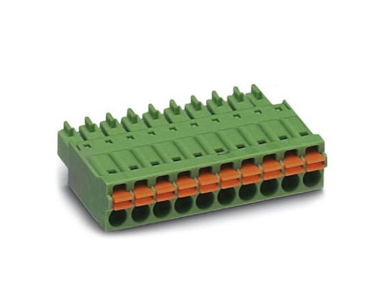
Phoenix Contact PCB Connector - 14 pos. push-in spring connection
This 14-way MonoDAQ-compatible connector allows the user to create, reuse and archive test fixtures instead of rewiring the connector furnished with the MonoDAQ everytime a measurement or test has to be repeated. Helps the user to build a library of plug-and-play test setups. Features Time saving push-in connection, tools not required Defined contact force ensures that contact remains stable over the long term Intuitive use through colour coded actuation lever Operation and conductor connection from one direction enable integration into front of device All necessary technical data can be found here.
€ 8,95
Members € 8,06
-

Elektor September/October 2025 (EN)
Elektor GREEN and GOLD members can download their digital edition here. Not a member yet? Click here. ESP32 Audio Transceiver Board (Part 2)Wireless Audio Transmission Inductive AM TransmitterUses Pico’s PIO in an Arduino Sketch Navigating Wireless ProtocolsA Technical Guide Satellite Tracking Using LoRaThe TinyGS Network Bringing Space Data to Earth 4G-Compatible SMS Remote ControlRemotely Control Your Equipment High-Speed ProbeHigh-Impedance Inputs for Signals up to 200 MHz From Life’s ExperienceKafka KrakenSDR Performance Tests with the RP2350Is an Upgrade from Raspberry Pi Pico 1 to Pico 2 Worthwhile? Contact-Free E-Field Measurements (2)A Laser Vibrometer for Assessing the Membrane's Vibrations Crystals and OscillatorsImproving Crystal Accuracy Through Capacitor Selection Starting Out in ElectronicsSpecial Audio ICs Getting Started with Coding a DIY Project SPECTRAN® V6 MobileModular, Configurable Real-Time Spectrum Analyzer for Reliable Measurements Across All Frequency Ranges The Future of AI Is Forged in SiliconAn Interview with Anastasiia Nosova Autonomous Sensor Node v2.0 (System Architecture)Solar-Powered Sensing Platform with Integrated GPS, LoRaWAN, and More Precise PositioningBluetooth Channel Sounding Tested Powering the Future of Wireless CommunicationBTRY’s Ultra-Thin Solid-State Batteries Test-Driven Development in Firmware Writing Phone-Controlled Model CarWi-Fi + ESP32 + Smartphone = Remote Control 2025: An AI OdysseyAI Reasoning Models: The Chain-of-Thought Revolution Solar Charge Controller with MPP Tracking (3)Software and Commissioning Raspberry Pi Zero Web Streaming CameraUsing the ZeroTier VPN
€ 14,90
-
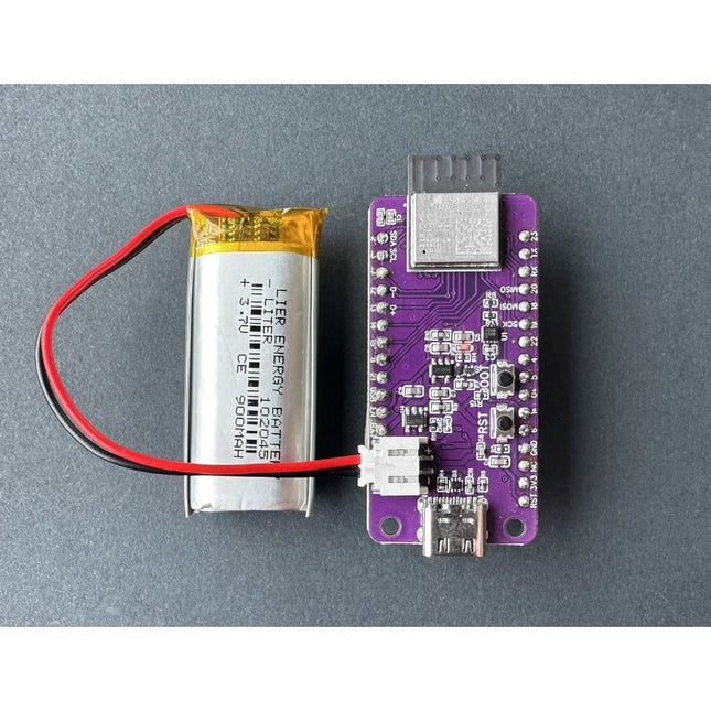
ThingPulse ThingPulse LiPo Battery for Color Kit Grande (900 mAh)
Enhance your ESP32 WiFi Color Display Kit Grande with this high-quality 900 mAh rechargeable lithium-polymer battery! Designed to provide long-lasting power, this battery ensures your projects remain portable and efficient. With its compact size and lightweight design, it’s the perfect accessory for any DIY electronics enthusiast. The battery offers reliable performance, easy integration, and safe, stable power supply, making it ideal for extended use in a variety of applications. 900 mAh LiPo battery JST Connector, fitting ePulse Feather
€ 16,95
Members € 15,26
-
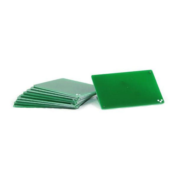
Voltera Voltera 2" x 3" FR1 Substrates
If you are going to be drilling, we recommend drilling on FR1 substrates. Unlike FR4, FR1 dust does not contain fiber glass. It is also a softer material, which means a less wear and tear on the drill bits. Download the template and incorporate them into your design here. 10 substrates included.
€ 19,95
Members € 17,96
-

Velleman Whadda Brain Game
4 LEDs and 4 push buttons ensure hours of fun. Repeat the combination, harder and harder, faster and faster. The microprocessor-controlled game has 4 different difficulty levels and low consumption. The sound and/or LED indication are adjustable. To save the three 1.5 V AA batteries (not included), the kit automatically switches itself off when not in use. Downloads Manual
€ 11,95
Members € 10,76


