A Small Basic Approach
There are many different PC programming languages available on the market. Some have beautiful names; some have easy to use development tools. Others have incredible power. They all have one thing in common: they assume that you have, or want to have, a knack for technology and difficult to read commands.
In this book we take a practical approach to programming. We assume that you simply want to write a PC program, and write it quickly. Not in a professional environment, not in order to start a new career, but for plain and simple fun... or just to get a task done.
Therefore we use Small Basic. You will have an application up and running in a matter of minutes. You will understand exactly how it works and be able to write text programs, graphical user interfaces, and advanced drivers. It is so simple; you don't even need to be an adult!
The Whadda 3D Xmas Tree Kit is aimed at hobbyists and beginners who are interested in soldering and electronics. With this DIY kit, you can build a festive LED Christmas tree.
Features
16 flashing red LEDs
Extra green and yellow LEDs provided to customise your tree
Can be hung on and fed through wires
Will operate on 12 V DC (e.g. in cars)
Specifications
Low power consumption
8 mA
Power supply
9 V battery operation (not included)
Dimensions
102 x 88 x 80 mm
Weight
65 g
Downloads
Manual
This book is about advanced programming of the Raspberry Pi computer using the Python programming language. The book explains in simple terms and with examples:
How to configure the Raspberry Pi computer;
How to install and use the Linux operating system and the desktop;
How to write advanced programs using the Python programming language;
How to use graphics in our programs;
How to develop hardware based projects using the Raspberry Pi.
The book starts with an introduction to the Raspberry Pi computer and covers the topics of purchasing all the necessary accessories and installing and operating the Linux operating system in command mode. The network interface of the RPi is explained in simple steps, demonstrating how the computer can be accessed remotely from a desktop or a laptop computer.
The remaining parts of the book cover the Python programming language in detail, including advanced topics such as operating system calls, multitasking, interprocess synchronization and interprocess communication techniques. The important topic of network programming using UDP and TCP protocols is described with working examples. The Tkinter graphical user interface module (GUI) is described in detail with example widgets and programs.
The last part of the book includes hardware projects based on using the advanced programming topics such as multitasking and interprocess communication techniques. All the projects given in the book have been fully tested and are working. Complete program listings of all projects are provided with detailed explanations.
This book is about the Raspberry Pi 3 computer and its use in various control and monitoring applications. The book explains in simple terms and with tested and working example projects, how to configure the Raspberry Pi 3 computer, how to install and use the Linux operating system, and how to write hardware based applications programs using the Python programming language.
The nice feature of this book is that it covers many Raspberry Pi 3 based hardware projects using the latest hardware modules such as the Sense HAT, Swiss Pi, MotoPi, Camera module, and many other state of the art analog and digital sensors. An important feature of the Raspberry Pi 3 is that it contains on-board Bluetooth and Wi-Fi modules. Example projects are given in the book on using the Wi-Fi and the Bluetooth modules to show how real-data can be sent to the Cloud using the Wi-Fi module, and also how to communicate with an Android based mobile phone using the Bluetooth module.
The book is ideal for self-study, and is intended for electronic/electrical engineering students, practising engineers, research students, and for hobbyists. It is recommended that the book should be followed in the given Chapter order.
Over 30 projects are given in the book. All the projects in the book are based on the Python programming language and they have been fully tested. Full program listings of every project are given in the book with comments and full descriptions. Experienced programmers should find it easy to modify and update the programs to suit their needs.
The following sub-headings are given for each project to make it as easy as possible for the readers to follow the projects:
Project title
Description
Aim of the project
Raspberry Pi type
Block diagram
Circuit diagram
Program listing
The field of digital electronics is central to modern technology. This e-book presents fundamental circuits using gates, flip-flops and counters from the CMOS 4000 Series. Each of the 50 experiments has a circuit diagram as well as a detailed illustration of the circuit’s construction on solderless breadboard.
Learning these fundamentals is best done using practical experiments. Building these digital circuits will improve your knowledge and will be fun to boot. Many of the circuits presented here have practical real-life applications. With a good overview of the field, you’ll be well equipped to find simple and cost-effective solutions for any application.
The e-book is targeted essentially at students, trainees and anyone with an interest in and requiring an introduction to digital control electronics. Moreover, the knowledge gleaned here is the foundation for further projects in the field of microcontrollers and programming.
Elektor GREEN and GOLD members can download their digital edition here.
Not a member yet? Click here.
Low-Noise Lab Power Supply (1)A Quiet Source for Sensitive Circuits
STM32 Edge AI Contest 2025: The Winners
Batteries TodayTechnology and Differences in Lithium Batteries
Adjustable Electronic LoadStatic + Dynamic DC Load
Step-Down Converter from 48 V to 5 VThe Story of Circuit Development
Autonomous Sensor Node v2.0Part 2: Hardware Validation and Power Optimizations
VaristorsPeculiar Parts, the Series
Graphical Grid Frequency MeterMonitor Grid Quality
Starting Out in Electronics……Brings Its Own End
Peak Current Load SMD FerritesMore Resilient Against Current Peaks
Elektor Live! Expert Day 2025
Energy Harvesting Set to Accelerate IoT and IIoT Use CasesHow Energy Harvesting Frees IoT from the Grid
Fnirsi DPS-150Compact and Portable Power Supply and Converter
Adjustable USB-C Power SourceTurn Your USB-C Charger Into an Adjustable Power Supply
Simple Charger and Capacity TesterWith Two Cheap “Off-the-Shelf” Modules
Smart Color Detector with AI Voice and Playback
PbMonitor v2.0Introduction to the Updated Battery Monitoring System
A Fan for the Mini Reflow PlateSmart Modifications That Improve Results
From Life’s ExperienceThe Tsunami of Indulgence
Err-lectronicsCorrections, Updates, and Readers’ Letters
2026: An AI OdysseyWhen Models Start Dictating the Hardware
Precision Picoammeter (2)Assembling, Calibration, and Test
Wireless Device Poweringwith Inductive Technology
AI-Based Autonomous DrivingThe RDW’s Self Driving Challenge 2024
Sound Card as Signal GeneratorPC as DCF77 Test Transmitter
Features
Internal LNA amplifier and selectable attenuator
Low frequency support from 50KHz covering LF, MF, HF, VHF and UHF up to 960Mhz
New HELP and SET buttons to improve user interface and configuration selection with 2-clicks
Wide band coverage to all popular sub-1Ghz bands, including FM, TV and DTV, ISM, RFID, GSM, etc.
Ideal choice for HAM bands from 160meters to 33cm
Pocket size and light weight
Solid metal case
Spectrum Analyzer mode with Peak Max and Hold, Normal, Overwrite and Averaging modes
High capacity internal Lithium battery for 20hs+ of continuous run, rechargeable by USB
Multi-platform Windows/Linux/MacOS Open Source software and API libraries
Can be extended with internal Expansion Modules for additional band and functionality
Specifications
Frequency band: 0.05 MHz - 960 MHz
Frequency span: 0.1 MHz - 960 MHz
Internal selectable LNA 25 dB gain
Internal selectable Attenuator 30 dB
Graphics LCD 128 x 64 pixels, great visibility outdoors
Support included for Windows, Linux and MacOS X
Backlight for great visibility indoor
Internal Lithium Ion 1800mA/h rechargeable battery
Standard SMA 50 Ω connector
Wideband 144/433MHz dual band telescopic antenna included
UHF 400-900 MHz rubber duck articulated antenna included
Amplitude resolution: 0.5dBm
Dynamic range: -125 dBm to 10 dBm
Absolute Max input power: +30dBm
Average noise level (typical LNA): -125 dBm
Frequency stability and accuracy (typical): +-10 ppm
Amplitude stability and accuracy (typical): +-2d Bm
Frequency resolution: 1kHz
Resolution bandwidth (RBW): automatic 2.6 kHz to 600 kHz
Included
1x RF Explorer WSUB1G+ Spectrum Analyzer
1x Mini USB cable
1x Dual band 144/430MHz Telescopic antenna
1x UHF 400-900Mhz antenna
1x EVA case
Features
Bandwidth: DC-800 KHz
Maximum measurable current: 100 Apk (70.7 Arms)
Max. conductor diameter: 13 mm
Auto & Manual "Zero" function
Directly powered by USB port
Standard BNC interface, compatible with any oscilloscope
Specifications
Bandwidth
DC-800 KHz
Rise time
<= 583 ns
Ranges
10 A / 100 A
Output sensitivity
0.1 V/A (10 A) 0.01 V/A (100 A)
DC accuracy
3% ±50 mA (10 A) 4% ±50 mA (100 A, 500 mA - 40 Apk) 15% (100 A, 40 Apk -100 Apk)
Signal delay
< 150 ns (10 A) < 200ns (100 A)
Current measurement range
50 mA - 10 Apk (10 A) 1 A - 100 Apk (100 A)
Max. Voltage
CAT III 300 V CAT II 600 V
Power supply
DC 5 V
Downloads
Quick Guide
Datasheet
Manual
The FNIRSI GC-03 is a multifunctional radiation detector designed for professional nuclear radiation measurement in everyday environments such as the home, office, car, and outdoors. Equipped with a 2.4-inch high-definition color display, it provides real-time monitoring of nuclear radiation as well as electric and magnetic field strength. For added safety, the device features three alarm modes: audible alert, vibration, and visual light warning.
Features
3-in-1 Detection: Monitors electric, magnetic, and nuclear radiation with one device.
High-Precision GM Tube: Accurately detects gamma, X-rays, and hard beta radiation with low power consumption.
Real-Time Curve + 50 Alarm Records: Tracks radiation trends and stores alarm history for easy review.
Custom Triple Alarms: Supports visual, audible, and vibration alerts with adjustable thresholds.
Long Battery Life: 1500 mAh battery for extended and reliable field use.
Specifications
Nuclear Radiation
Range: 0.01μSv/h-999.99μSv/h
Accuracy: 0.01μSv/h
Electric Field
Range: 1V/m-1999V/m
Accuracy: 1V/m
Magnetic Field
Range: 0.01μT-99.99μT
Accuracy: 0.01μT
Radiation Power
0.2-1000mW/m²
Detection Radiation Type
Ionizing radiation (gamma rays, etc.)
Detector
Energy compensation GM tube (Geiger counter tube)
Dose Current Rate
0.00-10000μSv/h (10mSv/h)
Cumulative Dose Equivalent
0.00μSv-500.0mSv
Energy Range
48keV-1.5MeV ≤ ±30% (for 137Cs-)
Sensitivity
80CPM/μSv
Dose Unit
μSv/h, uGy/h, mR/h, CPS, CPM
Alarm Mode
Light, vibration, sound
Display
2.4-inch color screen
Backlight
Brightness Adjustable
Power Supply
USB-C (5 V/1 A)
Battery
1500 mAh
Languages
English, Chinese
Dimensions
138 x 63 x 32 mm
Weight
141 g
Included
1x FNIRSI GC-03 Radiation Detector
1x USB cable
1x Manual
Downloads
Manual
Firmware v1.0.4
High-quality soldering with the most important tools and consumables, ideal for universal soldering applications.
Features
Power unit, 1 channel
1-channel Soldering Station digital 90 W (95 W)
WTP 90: The soldering iron for universal use with power response tips. Tip family XNT & THM (high mass tips)
Lock function
Specifications
Dimensions W x D x H (mm): 149 x 138 x 101
Dimensions W x D x H (inch): 5.87 x 5.43 x 3.98
Weight (ca) in kg: 1.9
Channels: 1
Voltage: 230 V, 50/60 Hz
Heating output: 90 W (95 W)
Temperature accuracy °C: ±9
Display: Backlit LCD
Temperature range: Adjustable from 50°C - 450°C (150°F - 850°C)Adjustable temperature range varies among tools
Temperature stability °C: ±2
Temperature accuracy °F: ±17
Temperature stability °F: ±4
Temperature range (depends on tool) °C: 100-450
Temperature range (depends on tool) °F: 150-850
Equipotential balance: yes
Fuse: 0,5 A
WT compatible: yes
ESD-safe: yes
Power cord: EMEA
You can use RF Explorer 3G Combo equally well outdoor and indoor, and you can also connect it to a PC for extra functionality using standard mini-USB 2.0 connector.
This model includes a WSUB1G baseline unit plus an RFEMWSUB3G Expansion Module conveniently assembled and tested. It comes with two SMA connectors and two antennas,a dual band telescopic 144 / 430 MHz antenna for all Sub-GHz frequencies and a whip helical antenna for 2.4 GHz band. Additional, specific band antennas may be needed to cover efficiently some of the frequencies supported.
The combination of these two models offer the wide band coverage of the WSUB3G module, together with the highest sensitivity and quick response of the WSUB1G model for the popular sub-1GHz frequencies.
Features
Pocket size and light weight
Solid aluminum metal case
Includes a transport EVA carry case for RF Explorer
Spectrum Analyzer mode with Peak Max and Hold, Normal, Overwrite and Averaging modes
Lifetime free firmware upgrades available, open to community requested features
High capacity Lipo for 16 hours+ of continuous run, rechargeable by USB
Windows PC client Open Source
Can be extended with internal Expansion Modules for additional band and functionality
Wide band coverage to all popular RF frequencies, starting at 15 MHz and going up to 2.7 GHz. This includes very interesting frequency areas such as 2 m HAM radio, all VHF and UHF, FM radio, GPS, WiFi and WiMax, Bluetooth, etc.
Firmware: RF Explorer 3G Combo is delivered with upgraded firmware v1.09. Note some of the features and operation accuracy will be improved in upcoming free firmware revisions.
Specifications
Battery
Lithium Cells / Batteries contained in equipment UN3481 - PI967
Frequency band
15-2700 MHz
Frequency span
112 KHz - 600 MHz
Graphics LCD
128 x 64 pixels, great visibility outdoors
PC Windows client
supports Windows XP/Vista/Win7 both 32 and 64bits
Backlight
for great indoor visibility
2 standard SMA 50 ohms connector,
one for Sub-GHz wideband Nagoya NA-773 telescopic antenna included and another 2.4 GHz one for 15-2700 MHz band with helical antenna included.
Amplitude resolution
0.5 dBm
Dynamic range
Left SMA port (WSUB1G)
-115 dBm to 0 dBm
Right SMA port (WSUB3G)
-110 dBm to -10 dBm
Absolute Max input power
Left SMA port (WSUB1G)
+5 dBm
Right SMA port (WSUB3G)
+30 dBm
Average noise level (typical)
-110 dBm
Frequency stability and accuracy (typical)
+-10 ppm
Amplitude stability and accuracy (typical)
+-6 dBm
Frequency resolution
1 KHz
Resolution bandwidth (RBW)
automatic 3 KHz to 600 KHz
Weight
185 g
Size
113 x 70 x 25 mm
Included
RF Explorer 3G Combo
Nagoya NA-773 wideband telescopic antenna
2.4 GHz band antenna
EVA Case
Documentation
For more info and to get started with your RF Explorer, visit the start page.
For questions and support, please visit https://support.rf-explorer.com
The UT8803E is a portable, AC-powered 3⅚ digital multimeter with 6000 counts with automatic measuring range and large display with backlight. The UT8803E can be used to measure AC/DC voltage, AC/DC current, resistance, frequency, capacitance, inductance, triode (HFE), diode (LED), thyristor (SCR), and on-off switching.
Features
Extreme value and reference value operation, with analog bargraph
Multiple measurement parameters optional
D/Q parameters of capacitance and inductance can be measured
Measurement resolution 3.5-inch, maximum measurement value 5999
Specifications
Measurement Resolution
3⅚, Maximum Measurement Value 5999
Measurement Rate
2-3 measurements/s
DC Voltage Range
600 mV~1000 V
DC Current Range
600 µA~20 A
AC Voltage Range
600 mV~750 V (True RMS)
AC Current Range
600 µA~20 A (True-RMS)
Resistance Range
600 Ω~60 MΩ
Capacitance Range
6 nF~60 mF
Inductance Range
600 µH~100 H
Frequency Measurement Range
600 Hz~20 MHz
Duty Cycle Measurement Range
5%~95%
Mathematical Operation
Maximum, minimum, relative value, trend chart
Interface
USB device (can be connected to the upper computer control software)
Frequency response
100 KHz
Downloads
Datasheet
User Manual
Programming Manual
Software
Elektor GREEN and GOLD members can download their digital edition here.
Not a member yet? Click here.
PIO Programming on the Raspberry Pi PicoNine Instructions, Many Possibilities
Breaking AI Out of the BrowserUsing AI CLIs to Code, Compile, and Validate Embedded Projects
The Scrutiny DebuggerDebug, Visualize, and Test Embedded C/C++ Code
Sigfox Breakout Board (1)A Self-Built Radio BoB
Low-Noise Power Supply (2)Construction, Assembly, and Practical Implementation
Simple Signal Generator Using the RP2040Analog and Digital Signals for Around €10
Navigating the Future of Smart Homes with Matter and Edge AIAre Matter’s Latest Updates and the Rise of Edge AI Finally Giving Engineers the Tools to Build the Intelligent, Seamless Smart Homes Users Have Been Promised?
Differential Pressure SensorsPredictive Maintenance in HVAC-Systems
Security by DesignEngineering Fundamentals Limit Failure
Embedded Security Is No Longer Optional
CRA and PQC Are Rewriting Embedded Security PrioritiesWhy Even Small IoT and Industrial Firms Need an Upgrade Plan
embedded world 2026An Interview With Benedikt Weyerer, Executive Director of embedded world
Hands on with I3CUsing Hardware from ST and Microchip
The BLEnky ProjectRapid Prototyping of Bluetooth Low Energy Applications
Pulse Width ModulationFrom a Simple On/Off Thermostat to a Smoothed DC Analog Signal
AudiotronicsEar-Pleasing Electronics for DIY Construction
From Life’s ExperienceRead The F...ing Manual!
ESP32 Audio Transceiver Board (Part 4)Tuning the Clocks - And a Wired Option
2026: An AI OdysseyThe 2025 Vibe-Coding Hangover
Symmetrical DC LoadDC Load, Static or Dynamic, and Symmetrical
Counting Faces with MaixCAMAn Easy Way to Capture Audience Sizes
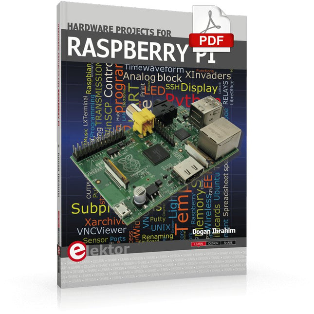
The Raspberry Pi is a $35 credit-card sized computer with many applications, such as in desktop computing, audio and video playback, and as a controller in many industrial, commercial and domestic applications.
This book is about the Raspberry Pi computer and its use in control applications. The book explains in simple terms, with examples, how to configure the RPi, how to install and use the Linux operating system, how to write programs using the Python programming language and how to develop hardware based projects.
The book starts with an introduction to the Raspberry Pi computer and covers the topics of purchasing all the necessary equipment and installing/using the Linux operating system in command mode. Use of the user-friendly graphical desktop operating environment is explained using example applications. The RPi network interface is explained in simple steps and demonstrates how the computer can be accessed remotely from a desktop or a laptop computer.
The remaining parts of the book cover the Python programming language, hardware development tools, hardware interface details, and RPi based hardware projects. All the 23 projects given in the book have been tested and are working.
The following headings are given for each project:
Project title
Project description
Project block diagram
Project circuit diagram
Project program description using the Program Description Language (PDL)
Complete program listing
Description of the program
The book is ideal for self-study, and is intended for electronic/electrical engineering students, practising engineers, research students, and hobbyists.
The Piccolino rapid development board can be used to design microcontroller circuits quickly. The Piccolino has a fast 16f887 PIC microcontroller, voltage regulator, and communications module, and can be easily extended using its four headers.
This e-book contains 30 projects based on the Piccolino. We'll use its unique communications facilities and get the Piccolino to communicate with programs on a PC. On the PC, we use the free programming language Small Basic. You can use this to create Windows programs with buttons and graphs quickly. You will learn how to analyze components such as inductors, capacitors, and OPAMPs, and how to display the measurement results in a graphical format. This will help you to design your circuits easily.
We will then start to adapt to the Piccolino. We'll add components to it to make it more powerful, with extra features such as flow control and digital to analog conversion. The clear instructions will enable you to design and build your adaptations. This way you can make your custom designed Piccolino.
We'll end up making an extension: a PCB that that can be mounted on the Piccolino headers. As an example, we'll design and build an extension for an LCD. You can use the included board layout to make your PCB or have it made for you. At the same time, you will learn how to make your extensions. The only limitation is your imagination!
The clear descriptions along with circuit diagrams and photos, will make the building of these projects an enjoyable experience. Each project has a clear explanation of the reasons why it was designed in a particular way. This helps you learn a lot about the Piccolino, as well as Small Basic, and the components that are used in this e-book. You can adapt the projects to suit your requirements or combine several projects.
The Internet of Things (IoT) is a new concept in intelligent automation and intelligent monitoring using the Internet as the communications medium. The “Things” in IoT usually refer to devices that have unique identifiers and are connected to the Internet to exchange information with each other. Such devices usually have sensors and/or actuators that can be used to collect data about their environments and to monitor and control their environments. The collected data can be processed locally or it can be sent to centralized servers or to the cloud for remote storage and processing. For example, a small device at the size of a matchbox can be used to collect data about the temperature, relative humidity and the atmospheric pressure. This data can be sent and stored in the cloud. Anyone with a mobile device can then access and monitor this data at any time and from anywhere on Earth provided there is Internet connectivity. In addition, users can for example, adjust the central heating remotely using their mobile devices and accessing the cloud.
This book is written for students, for practising engineers and for hobbyists who want to learn more about the building blocks of an IoT system and also learn how to setup an IoT system using these blocks.
Chapter 1 is an introduction to the IoT systems. In Chapter 2, the basic concepts and possible IoT architectures are discussed. The important parts of any IoT system are the sensors and actuators and they are described briefly in Chapter 3. The devices in an IoT system usually communicate with each other and the important aspect of IoT communication is covered in Chapter 4. Chapter 5 proceeds with the features of some of the commonly used development kits. One of these, the Clicker 2 for PIC18FJ manufactured by mikroElektronika, can be used as a processor in IoT systems and its features are described in detail in Chapter 6. A popular microcontroller C language, mikroC Pro for PIC gets introduced in Chapter 7. Chapter 8 covers the use of a click board with the Clicker 2 for PIC18FJ development kit. Similarly, the use of a sensor click board is described as a project in Chapter 9, and an actuator board in Chapter 10. Chapters 11 and 12 cover Bluetooth and Wi-Fi technologies in microcontroller based systems, and the remaining chapters of the book demo the creation of a simple Wi-Fi based IoT system with cloud-based data storage.
This book has been written with the assumption that the reader has taken a course on digital logic design and has been exposed to writing programs using at least one high-level programming language. Knowledge of the C programming language will be very useful. Also, familiarity with at least one member of the PIC series of microcontrollers (e.g. PIC16 or PIC18) will be an advantage. The knowledge of assembly language programming is not required because all the projects in the book are based on using the C language. If you are a total beginner in programming you can still access the e-book, but first you are advised to study introductory books on microcontrollers.
Elektor GREEN and GOLD members can download their digital edition here.
Not a member yet? Click here.
PbMonitor v2.0 UpdateBattery Monitoring with Improved Analog Design
Audio Latency MeasurementA Standalone Tool for Evaluating Errors and Latency in Audio Transmission
Square Wave vs. Bode PlotChecking the Performances of an Audio Device
embedded world 2026
Clever Coding with AIAI in Software Development for Electronics Engineers
QA403 Audio AnalyzerAffordable Precision for Audio Professionals and Hobbyists
EasyGimbalAutonomous Camera Tracking with AI, Stepper and Servo Motors
Sigfox Breakout Board (2)Sending Messages
Circuit ProtectionControlling Overvoltages with TVS Diodes
Emerging Battery Testing ApproachesA New Era of Diagnostics
AudiotronicsA First Preamplifier
CANopenTermAn Open-Source Tool That Brings CAN to Makers and Engineers Alike
Stabilization of Operational AmplifiersAvoiding Feedback Instability
Err-lectronicsCorrections, Updates, and Readers’ Letters
Signal ConditioningTips and Tricks to Fit Voltage Ranges
TDR Attachment for OscilloscopesLength, Short Circuit, Mismatch: Measure Cables Using Reflections!
From Life's ExperienceLED It Be
Speaker Oscillator and Resonance TesterA Fully Experimental Project for Your Speakers
Elektor Community Perspectives on Test and Measurement
ESP32 Audio Transceiver Board (Part 5)Audio Processing and Remote Control
2026: An AI OdysseyAI Has a Context Problem
Battery Storage for Balcony Power PlantsSmall Batteries, Big Impact
This bundle includes the Red Pitaya STEMlab 125-14 PRO Gen 2 Starter Kit and the new book "Experimenting with Red Pitaya STEMlab Gen 2".
The Red Pitaya STEMlab 125-14 PRO Gen 2 Starter Kit is a powerful and flexible platform for signal processing, data acquisition, and electronic measurement applications. Designed for engineers, developers, researchers, and educators, this kit provides everything required to start building advanced measurement and control systems.
At the core of the kit is the STEMlab 125-14 PRO Gen 2 board, an upgraded and ultra-lightweight development platform. Powered by the Xilinx Zynq-7010 SoC with 512 MB of RAM, it combines FPGA programmability with ARM processing power to enable high-performance instrumentation and custom signal-processing solutions.
The board offers 14-bit ADC and DAC resolution, a 125 MS/s sampling rate, an input range of ±20 V, and up to 60 MHz bandwidth. Its improved low-noise analog front-end, USB-C connectivity, and compact design make it suitable for demanding applications such as RF development, radar systems, photonics research, software-defined radio (SDR), and industrial automation.
The Starter Kit includes all essential accessories for immediate use: a microSD card with preinstalled operating system, power supply, Ethernet cable for remote access, two 100 MHz oscilloscope probes, and SMA-to-BNC adapters for flexible signal connections.
The Red Pitaya STEMlab 125-14 PRO Gen 2 Starter Kit is an excellent platform for rapid prototyping, FPGA development, measurement instrumentation, and advanced electronics experimentation.
Features
14-bit ADC and DAC resolution
125 MS/s sampling rate
±20 V input range
Up to 60 MHz bandwidth
Xilinx Zynq-7010 SoC (FPGA + ARM processor)
512 MB RAM
Low-noise analog front- and back-ends
Applications
RF development and testing
Radar and wireless systems
Software-defined radio (SDR)
Photonics and optical research
Industrial automation and control systems
Signal analysis and instrumentation
Rapid prototyping of electronic measurement systems
Specifications
Processor
Dual-core ARM Cortex-A9
FPGA
AMD Xilinx Zynq-7010 SoC
RAM
512 MB (4 Gb)
Storage
microSD card (up to 32 GB)
Operating System
Linux-based Red Pitaya OS
ADC Resolution
14-bit
DAC Resolution
14-bit
Bandwidth
60 MHz (DC)
Sampling Rate
125 MS/s
Analog Input Channels
2
Analog Output Channels
2
Input Voltage Range
±1 V (LV) / ±20 V (HV)
Input Impedance
1 MΩ / 10 pF
Output Voltage Range
±1 V
Ethernet
1x Gigabit Ethernet (RJ45)
USB
2x USB-C 2.0 (for power and console)
Digital I/O
16x GPIO (3.3 V)
Communication Interfaces
I²C, SPI, UART, CAN
Power Supply
5 V/3 A via USB-C
Dimensions
106.8 x 60.0 x 17.9 mm
Included
1x Red Pitaya STEMlab 125-14 PRO Gen 2 board
2x 100 MHz oscilloscope probes
2x SMA-to-BNC adapters
1x microSD card with preinstalled OS
1x USB-C Power supply
1x Ethernet cable
Downloads
Documentation
Schematics
Book: Experimenting with Red Pitaya STEMlab Gen 2
With this new book, Red Pitaya goes beyond a versatile board. It becomes a powerful laboratory instrument for precision measurement, analysis, and control.
From the fundamentals of electronic project development, monitoring, control, and design to testing, this book walks you step-by-step through everything you need to know to harness the full potential of Red Pitaya hardware and software.
The book presents real-time, FPGA-based projects that are developed on a PC using the Vivado environment, then transferred to the Red Pitaya for execution and testing.
You will learn about enhanced performance, expanded I/O capabilities, improved FPGA features, and advanced connectivity options that open up new frontiers for precision measurement, monitoring, and control in your embedded applications.
Inside the book you will discover:
A deep dive into Red Pitaya architecture and hardware design
Electronic experiments using Red Pitaya for measurement and monitoring
Hands-on projects using the Python programming language
Practical guidance for FPGA programming using Red Pitaya
Red Pitaya FPGA projects using the Verilog HDL under Vivado IDE
Practical design of electronic projects including measurement and testing
Step-by-step examples that bridge theory and real-world implementation
Whether you are designing your own electronic circuits, developing signal analysis tools, or creating real-time control or monitoring systems, this book provides you the knowledge and confidence you need to fully learn and customize the Red Pitaya platform.
The Siglent SDS1204X-E is a powerful 200 MHz four-channel oscilloscope that is built on the same platform as the very popular SDS1202X-E but with several significant improvements, including two 1 GSa/s ADCs and two 14 Mpt memory modules. Waveform capture rates are up to 100,000 wfms/s in normal mode and 400,000 wfms/s in sequence mode. The SDS1000X-E scopes feature a large 7” 256-level color display with intensity grading and color temperature features.
Specifications
Bandwidth
200 MHz
Sampling Rate (Max.)
1 GSa/s
Channels
2CH+EXT4CH
Memory Depth (Max.)
7 Mpts/CH (not interleave mode); 14 Mpts/CH (interleave mode)
Waveform Capture Rate (Max.)
100,000 wfms/s (normal mode), 400,000 wfms/s (sequence mode)
Trigger Types
Edge, Slope, Pulse width, Window, Runt, Interval, Dropout, Pattern, Video
Serial Trigger (Standard)
I²C, SPI, UART/RS232, CAN, LIN
Decode Type (Standard)
I²C, SPI, UART/RS232, CAN, LIN
16 Digital Channels (four channel series only, option)
Maximum waveform capture rate up to 1 GSa/s, Record length up to 14 Mpts/CH
USB AWG module (four channel series only, option)
One channel, 25 MHz, sample rate of 125 MHz, wave length of 16 kpts
Bode plot ( four channel series only)
Minimum start frequency of 10 Hz, minimum scan bandwith of 500 Hz, maximum scan bandwidth of 120 MHz (dependent on Oscilloscope and AWG bandwidth), 500 maximum scan frequency points
USB WIFI adapter (four channel series only, option)
802.11b/g/b, WPA-PSK, the adapter must be supplied by Siglent to ensure proper functioning
Downloads
Datasheet
Manual
Programming Guide
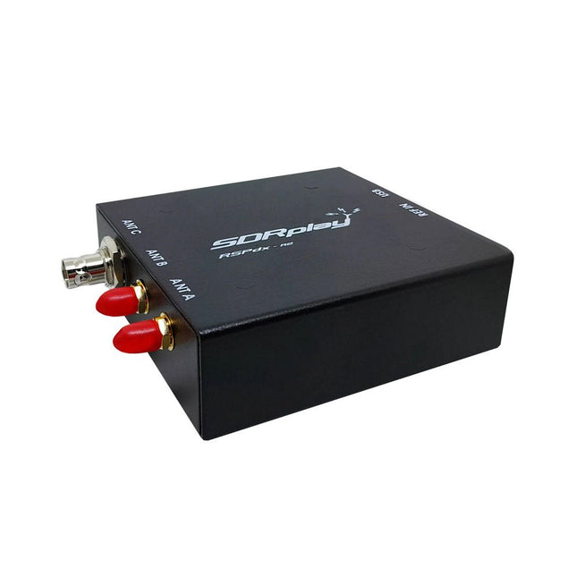
The SDRplay RSPdx-R2 is a wideband full featured single-tuner 14-bit SDR receiver which covers the entire RF spectrum from 1 kHz to 2 GHz giving up to 10 MHz of spectrum visibility. It contains three antenna ports, two of which use SMA connectors and operate across the full 1 kHz to 2 GHz range and the third uses a BNC connector which operates up to 200 MHz.
The RSPdx-R2 is an enhanced version of the RSPdx with further design improvements for use at frequencies below 2 MHz. Housed in a strong steel case, in addition to the functionality of the RSP1B, the RSPdx-R2 provides three software selectable antenna inputs and an external clock input. It offers excellent performance through HF and VHF frequencies all the way up to 2 GHz. The RSPdx-R2 also supports an "HDR mode" optimised for the demanding radio reception conditions below 2 MHz.
The RSPdx-R2, when used in conjunction with SDRplay’s own software, introduces a special HDR (High Dynamic Range) mode for reception within selected bands below 2 MHz. HDR mode delivers improved intermodulation performance and fewer spurious responses for those challenging bands.
Features
Covers all frequencies from 1 kHz through VLF, LF, MW, HF, VHF, UHF and L-band to 2 GHz, with no gaps
Receive, monitor and record up to 10 MHz of spectrum at a time
Significantly improved noise performance below 1 MHz (i.e. for some MF, LF and below)
Improved dynamic range below 2 MHz both in tuner mode and HDR mode
HDR mode below 2 MHz giving overall dynamic range and selectivity advantages
Software selectable choice of 3 antenna ports
External clock input for synchronisation purposes, or connection to GPS reference clock for extra frequency accuracy
Excellent dynamic range for challenging reception conditions
Free use of Windows-based SDRuno software (check website for versions supported)
Free use of SDRconnect SDR and server software for Windows, MacOS and Linux (Check website for versions supported)
Multiplatform driver and API support including Windows, Linux, Mac and Raspberry Pi 4/5
Strong and growing software support network
Calibrated S meter/RF power and SNR measurement with SDRuno (including datalogging to .CSV file capability)
Documented API provided to allow demodulator or application development on multiple platforms
Applications (Amateur)
Shortwave radio listening
Broadcast DXing (AM/FM/TV)
Panadaptor
Aircraft (ADS-B and ATC)
Slow Scan TV
Multi-amateur band monitoring
WSPR & digital modes
Weather fax (HF and satellite)
Satellite monitoring
Geostationary environmental satellites
Trunked radio
Utility and emergency service monitoring
Fast and effective antenna comparison
Applications (Industrial)
Spectrum Analyser
Surveillance
Wireless microphone monitoring
RF surveying
IoT receiver chain
Signal logging
RFI/EMC detection
Broadcast integrity monitoring
Spectrum monitoring
Power measurement
Applications (Educational/Scientific)
Teaching
Receiver design
Radio astronomy
Passive radar
Ionosonde
Spectrum analyser
Receiver for IoT sensor projects
Antenna research
Specifications
Frequency Range
1 kHz – 2 GHz
Antenna Connector
SMA
Antenna Impedance
50 Ohms
Current Consumption (Typical)
190 mA @ >60 MHz (excl. Bias-T)120 mA @ <60 MHz (excl. Bias-T)
USB Connector
USB-B
Maximum Input Power
+0 dBm Continuous+10 dBm Short Duration
ADC Sample Rates
2-10.66 MSPS
ADC Number of Bits
14 bit 2-6.048 MSPS12 bit 6.048-8.064 MSPS10 bit 8.064-9.216 MSPS8 bit >9.216 MSPS
Bias-T
4.7 V100 mA guaranteed
Reference
0.5ppm 24 MHz TCXOFrequency error trimmable to 0.01ppm in field
Operating Temperature
−10˚C to +60˚C
Dimensions
113 x 94 x 35 mm
Weight
315 g
Downloads
Datasheet
Software
RSPdx-R2 vs RSPduo
RSPdx-R2
RSPduo
Continuous coverage from 1 kHz to 2 GHz
✓
✓
Up to 10 MHz visible bandwidth
✓
✓
14-bit ADC silicon technology plus multiple high-performance input filters
✓
✓
Software selectable AM/FM & DAB broadcast band notch filters
✓
✓
4.7 V Bias-T for powering external remote antenna amplifier
✓
✓
Powers over the USB cable with a simple type B socket
✓
✓
50Ω SMA antenna input(s) for 1 kHz to 2 GHz operation (software selectable)
2
2
Additional software selectable Hi-Z input for up to 30 Mhz operation
✓
Additional software selectable 50Ω BNC input for up to 200 MHz operation
✓
Additional LF/VLF filter for below 500 kHz
✓
24 MHz reference clock input (+ output on RSPduo)
✓
✓
Dual tuners enabling reception on 2 totally independent 2 MHz ranges
✓
Dual tuners enabling diversity reception using SDRuno
✓
Rugged black painted steel case
✓
✓
Overall performance below 2 MHz for MW and LF
++
+
Multiple simultaneous applications
+
++
Performance in challenging fading conditions (*using diversity tuning)
+
*++