Bestsellers
-

iFixit iFixit Magnetic Project Mat
The 8x10" iFixit Magnetic Project Mat catches and securely holds screws as you pull them out of a device. Now you can stop worrying about keeping track of all the loose screws and focus on your repair. Screws and small parts will remain right where you left them. For laptops with hundreds of screws, use the whole mat as a screw guide and keep careful location notes. Included is a pen – made by Staedtler, producer of top-of-the-line pens and pencils for artists and architects – that was specially designed for the Project Mat. The Lumocolor Correctable pen resists smears and won't wipe away with a casual brush of your hand. When your repair is complete, use the eraser tip or a dry cloth to wipe the ink away clean. Features Organize all your small parts while you work on a device. The dry-erase surface lets you keep notes and location sketches. Reduces reassembly time by up to 40% while preventing errors.
€ 19,95
-

Elektor Edge Impulse Guest Edition 2025 (EN)
Elektor GREEN and GOLD members can download their digital edition here. Not a member yet? Click here. What to expect This Elektor edition guest-edited by Edge Impulse explores the edge AI workflow, from data collection and model training to deployment and optimization: End-to-End Edge AIA hands-on object detection series that walks through the complete machine learning pipeline on embedded hardware. High-Resolution, High-Speed Object Counting (Nvidia Jetson Nano, TensorRT)Pushing inference speed and precision for visual counting applications. PCB Defect Detection with Computer Vision (Raspberry Pi)Smarter manufacturing through embedded vision. Smart Building Ventilation with Sensor FusionAI-powered environmental optimization for energy efficiency. Analog Meter Reading (Arduino Nicla Vision)A TinyML approach to automating analog infrastructure. Smart Appliance Control Using Voice Commands (Nordic Thingy:53)Speech recognition at the edge. Liquid Classification with TinyML (Seeed Wio Terminal + TDS Sensor)Combining IoT sensing and embedded ML for fluid analysis. Surgery Inventory Object DetectionApplying real-time vision to healthcare logistics. Plus, the magazine includes exclusive interviews with: Edge Impulse co-founders Zach Shelby and Jan Jongboom; Qualcomm Technologies VP of product management Manny Singh; and EDGE AI FOUNDATION CEO Pete Bernard. Also included are a Tech the Future essay titled "AI at the Edge: Powering the Next Generation of Devices," an Industry Case Study on GlobalSense, and more. Contents What the Heck Is Edge AI Anyway?Bringing Intelligence to the Device Meet Edge Impulse StudioEasily Build and Deploy Edge AI Models Keyword Spotting with Edge ImpulseCollect, Train, and Deploy Smart Appliance Control Using Voice Commands with the Nordic Thingy:53 Key Terms for Understanding Edge AI and Machine Learning Crash Course: Getting Started with Edge ImpulseLearn to Collect, Train, and Deploy an ML Model with the Arduino Nano 33 BLE Sense A New Chapter for ArduinoFrom Hobby Board to Edge Computing Powerhouse Getting Started with Object Detection on Edge Devices PCB Defect DetectionComputer Vision with Raspberry Pi Scaling AI to the Smallest Devices Optimizing Power Efficiency in Battery-Driven Edge AI Devices AI ToasterWhen Edge AI Meets Breakfast Thundercomm Rubik Pi 3Raspberry Pi Familiarity Meets Edge AI Leadership, Embedded ML, and the Edge Revolution Vision Language Models for the EdgeCascading Models for Better Reliability Get to Know Edge ImpulseQuestions from the Elektor Community Project Update #5: ESP32-Based Energy MeterUsing Edge AI to Recognize Household Loads Motion Recognition with Anomaly DetectionAn End-to-End Tutorial Smart Ventilation System: Fusing Sound and Environmental DataA Dual-MCU Machine Learning Approach for Automated Window and Louver Control Bringing Voice Control to Earbuds and Headsets AI at the Edge: Powering the Next Generation of Devices
€ 14,90
-
Elektor Digital 311 Circuits (E-book)
311 Circuits is the twelfth book in Elektor’s celebrated ‘300’ series. An immense source of inspiration for all electronics enthusiasts and professionals, this book deserves a place not far from the workbench. This book contains circuits, design ideas, tips and tricks from all areas of electronics: audio & video, computers & microcontrollers, radio, hobby & modelling, home & garden, power supplies & batteries, test & measurement, software, not forgetting a section ‘miscellaneous’ for everything that doesn’t fit in one of the other categories. 311 Circuits presents complete solutions for numerous problems, as well as starting points for your own creations. 311 Circuits has been compiled from the 2009, 2010 and 2011 ‘Summer Circuits’ double editions of Elektor magazine. The book is mostly based on readers’ contributions, supplemented by circuits engineered and developed in the Elektor Labs.
€ 29,95
Members: € 26,96
-

Elektor Publishing SDR with HackRF One & HackRF Pro
Programming with GNU Radio HackRF is an open-source hardware platform developed by Great Scott Gadgets and serves as a versatile front end for software-defined radio (SDR). With HackRF One and its successor, HackRF Pro, users can develop their own SDR applications, build powerful receivers and transmitters, and tackle demanding RF measurement tasks. This book provides a practical introduction to the world of SDR. Step by step, the author shows how powerful SDR projects can be implemented with HackRF – from the fundamentals of RF technology to advanced applications using GNU Radio. In addition to working with SDR Sharp (SDR#), RadioConda, and GNU Radio, the book also covers the fundamentals of modern digital signal processing. Numerous experiments and easy-to-follow practical examples guide readers through topics such as AM, FM, and SSB reception, digital filters, shortwave radio, amateur radio, signal generators, and custom RF projects up to 6 GHz. Whether you are a maker, radio amateur, electronics enthusiast, or SDR beginner, this book provides solid knowledge, practical applications, and the motivation to creatively explore the possibilities of modern SDR technology.
€ 24,95
Members: € 22,46
-
Elektor Digital Elektor November/December 2020 (PDF)
Elektor Magazine EN November/December 2020 (PDF)
€ 7,50
-
Elektor Digital 309 Circuits (E-book)
The present tenth edition of the popular ʻ30x Circuitsʼ series of books once again contains a comprehensive variety of circuits, sub-circuits, tips and tricks and design ideas for electronics. These 309 Circuits again offer a representative indication of present-day electronics. Regular ʻ30x seriesʼ enthusiasts will no doubt know what to expect: 309 Circuits contains many fully elaborated electronics projects. In addition, there are numerous ideas, each of which with a potential for use in your own research, projects and applications. Among many other inspiring topics, the following categories are well presented in this book: test & measurement; RF (radio); computers and peripherals; audio & video; hobby and modelling; microcontrollers; home & garden; power supplies & battery chargers; etcetera. 309 Circuits has been compiled from the contents of Elektor Electronics' Summer Circuits editions for the years 2003, 2004 and 2005. Summer Circuits is the annual double issue of Elektor Electronics magazine covering the months of July and August.
€ 29,95
Members: € 26,96
-

Siglent Siglent SDG2042X 2-ch Arbitrary Waveform Generator (40 MHz)
Siglent's SDG2000X is a series of dual-channel function/arbitrary waveform generators with specifications of up to 120 MHz maximum bandwidth, 1.2 GSa/s sampling rate and 16-bit vertical resolution. The proprietary TrueArb & EasyPulse techniques help to solve the weaknesses inherent in traditional DDS generators when generating arbitrary, square and pulse waveforms. With advantages above, SDG2000X can provide users with a variety of high fidelity and low jitter signals, which can meet the growing requirements of complex and extensive applications. Features Dual-channel, 40 MHz bandwidth, 20Vpp maximum output amplitude, high fidelity output with 80dB dynamic range. High-performance sampling system with 1.2GSa/s sampling rate and 16-bit vertical resolution. No detail in your waveforms will be lost. Innovative TrueArb technology, based on a point-by-point architecture, supports any 8pts~8Mpts Arb waveform with a sampling rate in range of 1μSa/s~75MSa/s. Innovative EasyPulse technology, capable of generating lower jitter Square or Pulse waveforms, brings a wide range and extremely high precision in pulse width and rise/fall times adjustment. Plenty of analog and digital modulation types: AM, DSB-AM, FM, PM, FSK, ASK and PWM. Sweep and Burst functions. High precision Frequency Counter. Standard interfaces: USB Host, USB DeviceUSBTMC, LAN (VXI-11) Optional interface: GPIB. 4.3” touch screen display for easier operation. Specifications Maximum output frequency 40 MHz Output channels 2 Sampling rate 1.2 GSa/s (4X Interpolation) Wave length CH1: 16 Kpts, CH2: 512 Kpts Frequency resolution 1 μHz Vertical resolution 16 bit Standard interfaces Standard interfaces: USB Host, USB Device (USBTMC), LAN (VXI-11) High-performance Sampling System Benefiting from a 1.2GSa/s and 16-bit sampling system, SDG2000X achieves extremely high accuracy performance in both time domain and amplitude, which results in more accurately reconstructed waveforms and lower distortion. Innovative EasyPulse Technology When a Square/Pulse waveform is generated by DDS, there will be a one-clock-jitter if the sampling rate is not an integer-related multiple of the output frequency. SDG2000X EasyPulse technology successfully overcomes this weakness in DDS designs and helps to produce low jitter Square/Pulse waveforms. Innovative TrueArb Technology For arbitrary waveforms, TrueArb not only has all the advantages of traditional DDS, but also eliminates the probability that DDS may cause serious jitter and distortion. Easy controll with 4.3” Touch Screen Display and Arbitrary Waveform Software EasyWave The 4.3” touch screen display, makes operation much more convenient. And EasyWave is a powerful arbitrary waveform editing software that supports several ways to generate arbitrary waveform such as manual drawing, line-drawing, equation-drawing, coordinate-drawing, etc. It is quite convenient for users to edit their own arbitrary waveforms through EasyWave. Included Siglent SDG2042X Arbitrary Function Generator User Manual Guarantee Card CD (including EasyWave 1.0 computer software system) Power Cord USB Cable Quick Start Guide
€ 560,39
-

Siglent Siglent SPD3303X 3-ch DC Power Supply (220 W)
SPD3000X Series Linear Programmable DC Power Supply has a 4.3 inches TFT LCD display, Supports Programmability and Real Time Wave Display, bringing a new experience to users. It has three isolated outputs: two adjustable channels and one selectable channel from 2.5V, 3.3V, and 5V. It also has output short and overload protect function, and can be used in production and development. Features 3 independent controlled and isolated output, 32V/3.2A×2, 2.5V/3.3V/5V/3.2A×1, total 220W. 5 digits Voltage, 4 digits Current Display, Minimum Resolution: 1mV/1mA. Supports panel timing output functions. 4.3 inch true color TFT LCD 480x272 pixel display. 3 kinds of output modes: independent, series, parallel. 100V/120V/220V/230V compatible design to meet the needs of different power grids. Intelligent temperature-controlled fan, effectively reducing noise. Clear graphical interface, with the waveform display function Internal 5 groups of system parameter save/recall, supports data storage space expansion. Provides PC software: Easypower, supports SCPI, LabVIEW driver. High-resolution and high-precision output The highest resolution of 1mV/1mA, provides excellent setting and read back accuracy. This ensures accurate output even with very with small changes in voltage or current. This is impossible for a low resolution power supply. Series/parallel/independent mode function Series and parallel function allows two channels combined into one output with more power output capability, extending the application range. Each of 3 channels power can be turned on or off independently and also can be turned all on or all off. Panel displays the timing output Through the panel operation, 5 groups of timing settings and output control can be displayed, which provides users a simple power programming function. Also a connection can be made with Siglent’s EasyPower PC software providing a full range of communication and control requirements. Save/Recall setting parameters SPD3000X series programmable power supply can save or recall 5 groups of setting parameter in internal storage, also supports external storage expansion. You can easily obtain the settings you needed.
€ 600,50
-

Elektor July/August 2025 (EN)
Elektor GREEN and GOLD members can download their digital edition here. Not a member yet? Click here. OBD2 Sensor DashboardOld Dials Sparked a Quest for Real Data OBD2: Add a Rev Counter and Gear Shift Indicator to Your CarRetro, but Super Useful LiDAR and Vision Sensors for Robotics Sensor+Test 2025 and PCIM 2025 Contact-Free E-Field Measurements (1)A Vibrating Membrane for Assessing DC Voltages or Static Electric Fields Wireless Mailbox NotifierFrom Optical Sensors to Radar, Exploring a Few Options Elektor Mini-WheelieA Self-Balancing Robot Solar CellsPeculiar Parts, the Series Getting Started With a Modern Radar SensorIs an Accurate Measurement on Your Radar? From Life’s ExperiencePaper Factory CybersecurityTough Times for Hackers Siglent Presents Next-Gen Multi-Channel OscilloscopesHigh-Performance Solutions for Modern Power and Embedded Systems Bluetooth 6.0 Brings Enhanced Distance-Ranging ApplicationsNew Version Offers Improved Device Positioning and Location Services Exploring Wireless Communication with BeagleY-AI Err-lectronicsCorrections, Updates, and Readers’ Letters Starting Out in Electronics……Concludes the Topic on Opamps A Powerful AI Code AssistantSpeed Up Your Development with Continue and Visual Studio Code Solar Charge Controller with MPPT (2)The Circuit Ultrasonic Obstacle DetectorA Simple Project to Help Those with Impaired Vision 2025: An AI OdysseyMid-Year Review Raspberry Pi Standalone MIDI Synthesizer (3)Making It Smarter and Adding a User Interface Meshtastic: A Demo ProjectAn Intelligent Mesh of LoRa Radios Analog Audio Frequency GeneratorHigh-Quality Adjustable Frequency Sine Wave Generator
€ 10,95
-

Elektor Digital Elektor Circuit Special 2023 PDF (NL)
Elektor GREEN en GOLD leden kunnen deze uitgave hier downloaden.Nog geen lid? Klik hier om een lidmaatschap af te sluiten. Mini-zonnevoedingzon in, 3,3 V uit Solid-state stereo-audioschakelaarklikvrij en zonder bewegende onderdelen Grote RGB-digitmet through-hole WS2812 LED’s Microfoon-voorversterker met 48V-fantoomvoedingvoor podcasting en pro-audio Blokgolfgeneratoren met regelbare duty cycle en frequentiesimpele schakelingen met CMOS- en TTL-IC’s Eenvoudige dynamiekcompressorsofte aansturing, warm geluid Simpel elektronisch slot Actieve gelijkrichtervoor 2...40 V bij maximaal 3 A met tegenstroomonderdrukking Actieve boxen in- en uitschakelen Ongebalanceerd/gebalanceerd-convertermet RF-filter en DC-bescherming 2023: een AI-odysseewaar komt het vandaan en waar gaat het naar toe? Snelheidsregelaar voor ventilatormet handmatige en thermostaatmodus Laatste nieuwtjes van Arduino Project Hubnieuwe projecten uit de community Overbelastingsmonitorbewaakt netsnoeren Transistorloos knipperlicht in het donkeroscillator met alleen tweedraads onderdelen Morsecode-generatorvoor gebruik als baken of leermiddel! Programmeerbare video-DACvoor elk formaat tot RGB888 Kleintje klavierzonder bewegende onderdelen Dubbel-dobbel zonder microprocessordubbele dobbelsteen op een enkele print – plus enkele ontwerptrucs Elektronische vogelverschrikker Amusante, inspirerende en verbazingwekkende schakelingen LC/LP/HA-thermometernauwkeurige metingen en een binair display THD-generatorvervorming, maar dan opzettelijk Overtemperatuur-indicator met thyristorelektronische onderdelen ongebruikelijk gebruikt Een PTC-flipflop Sociale vogeleen tsjilpende Elektor Klassieker Neonlamp plus microcontroller Temperatuurgestabiliseerde IC-stroombronneutraliseer de temperatuurdrift van deze driebeners Regelbare tweede-orde hogetonen-boostergehoorsteuntje voor ouderen Edwin komt naar huisherinneringen na 53 jaar Eénarmige bandieteen eenvoudige, leuke, nostalgische en leerzame Elektor-klassieker! Eenvoudige digitaal gestuurde variabele weerstand Lekdetectorbeveiligt en alarmeert bij lekkages Eco-timer met automatische uitschakelingverbruikt niets in uitgeschakelde toestand! ChatGPT en Arduino Zenermetermeet de Z-spanning van Z-diodes ≤ 100 V Servotester ESP32 Windows-controller met gratis software Analoge en mixed-signal IC’s van Microchipzuinige signaalverwerking Interfacenormenfilter en overspanningsbeveiliging voor de I²C-bus Li-Ion accumonitorrestlading-indicator geeft visuele feedback PS/2-muis als draai-encoder (en meer...) Simpele schemerschakelaarvoor bestaande lampen of installaties Controller voor waterpompbereid je voor op hoogwater Kerstbal met FM-zonneradiomeer heb je voor de kerst niet nodig Trillingssensor met relaistik of schud om in te schakelen Doorgangstestergevoelig en niet storend In- en uitschakelen met een drukknop Regeling voor mini-boor (2023)een ontwerp uit 1980 herzien Digitale trillingssensorzet trillingen om in nauwkeurig getimede pulsen Ompoolbeveiliging met kleine spanningsval Goedkope frequentiestandaard Kleine DCF77-simulatornauwkeurige fake-tijdstandaard De Lilygo T-PicoC3combineert RP2040 en ESP32-C3 met een full-color TFT-display Hexadoku
€ 9,95
-
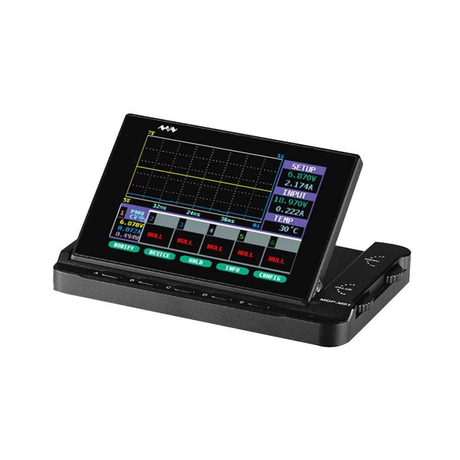
Miniware Miniware MDP-M01 Smart Digital Monitor
MDP-M01 is a display control module equipped with a 2.8-inch TFT display screen, the screen can be turned 90 degrees, which is convenient for users to view data and waveform. MDP-M01 can realize online display and control with MDP-P906 mini digital power supply modules and other modules of MDP system through 2.4 GHz wireless communication, and can control up to 6 sub-modules at the same time. Specifications Screen size 2.8" TFT Screen resolution 240 x 320 Power Micro USB power input, or taking power from sub-module via dedicated power cable Input DC 5 V/0.3 A Other functions Can control up to 6 sub-modulesUpgrade firmware through Micro USB Dimensions 107 x 66 x 13.6 mm Weight 133 g Included 1x MDP-M01 Smart Digital Monitor 1x Cable (2.5 mm jack to Micro USB) Downloads User Manual v3.4 Firmware v1.32
€ 79,00
-

Sensepeek Sensepeek 6012 PCBite Kit incl. 2x SQ10 Probe for DMM
The SQ series of handsfree PCBite probes from Sensepeek are insulated, come with included color-coded cable holders and have a lower point of gravity making them even more stable compared with the original SP series of probes. All the loved features of handsfree measurement, exchangeable fine pitch spring tipped test needle and the minimalistic design is maintained to make traditional sized and handheld probes obsolete. Features All handsfree probes from Sensepeek makes instant measurements or long triggering sessions a breeze. No more soldering wires to connect your probe or complicated tools to setup, just positioning the probe needle on any test point or component in the signal path and release. Saves time and frustration during development, verification and repairs. The minimalist design and the spring-loaded test needle makes it possible to simultaneously measure on fine pitch components and nearby signals. Both length and weight of the SQ probes are perfectly balanced to be used with PCBite PCB holders and base plate which is a must for handsfree function. The probe holder comes with a powerful magnet in the base, as for all PCBite probes and holders which makes the probe easy to place and reposition. The SQ series of probes can be used handheld without the probe holder as they have an insulated grip but their full potential is used when measuring handsfree. Included 4x PCBite PCB holders 2x SQ10 probes and pin tipped test needles (red/black) 2x Banana to dupont test wires (red/black) 1x Large Base plate (A4) 1x Insulation cover for the base plate (A4) 1x Set of yellow insulation washers for the PCB holders 1x Set of cable holders (red/black) 2x Extra test needles 1x Micro fiber cloth Downloads User Guide (PCBite Kit) User Guide (SQ10)
€ 127,05
-
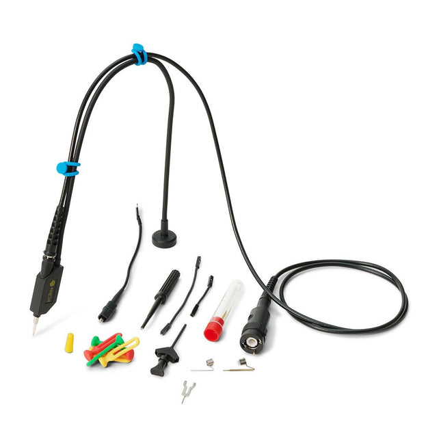
Sensepeek Sensepeek 6023 SQ350 (350 MHz handsfree Oscilloscope Probe)
The SQ series of handsfree probes from Sensepeek have a lower point of gravity making them even more stable compared with the original SP series of handsfree probes. All probes in the SQ series are also insulated and can be used handheld as any traditional probe but their full potential is used when measuring handsfree. The SQ series of oscilloscope probes also includes more ground options, have probe tip protection, longer cable and support for oscilloscopes with automatic scaling (10:1). All the loved features of handsfree measurement, exchangeable fine pitch spring tipped test needle, color-coded cable holders and the minimalistic design is maintained to make traditional sized and handheld probes obsolete. Both length and weight of the SQ probes are perfectly balanced to be used with PCBite PCB holders and base plate which is a must for handsfree function. Features Passive 10:1 probe with support for oscilloscopes with automatic scaling Spring-loaded test needle for fine pitch measurements Multiple ground options Color coded cable holders Probe tip protection Insulated, can be used handheld Improved probe holder for handsfree measurement when used with PCBite PCB holders Included 1x SQ350 350 MHz probe with spring tipped test needle 1x SQ probe holder for handsfree measurement 1x Testhook with detachable cables (5 cm & 10 cm) for convenient ground connection 1x Alligator cable for convenient ground connection 1x Standard ground spring, for handheld measurements at rated bandwidth 1x Unique ground spring, for total handsfree measurements at rated bandwidth 1x Set of color coded cable holders (4 colors) 1x Probe tip protection 1x Extra test needle Downloads User Guide SQXX0 Rev1.1
€ 107,69
-

Quick Quick 861DW Hot Air Rework Station (1000 W)
The Quick 861DW is an advanced Hot Air Rework Station with a 1000 W heating power. It is designed for professional soldering electronic SMD components using lead-free solders. Features Three programmable channels CH1, CH2 and CH3 (for air volume and temperature parameters). Password protection and button lock function available. Magnetic switch in a stand can automatically puts the station into sleep mode when not in use. Easy real-time operation, auto sleeping function available, parameters can be set in sleeping mode. Closed loop sensor, temperature controlled by micro-computer zero trigger, large power, rapid temperature rising, temperature can be easily and accurately adjusted, not affected by airflow. Brushless vortex fan, wide range of airflow adjustable, suitable for many applications. Auto cooling function available, long lifetime ceramic heater. Specifications Power 1000 W Operating voltage AC 200~240 V Temperature range 100-500°C Air volume 1-120 class Air flow 50 l/min (Max) Dimensions 188 x 245 x 135 mm Weight 3.65 kg Downloads Manual
€ 255,73
-

Elektor September/October 2025 (EN)
Elektor GREEN and GOLD members can download their digital edition here. Not a member yet? Click here. ESP32 Audio Transceiver Board (Part 2)Wireless Audio Transmission Inductive AM TransmitterUses Pico’s PIO in an Arduino Sketch Navigating Wireless ProtocolsA Technical Guide Satellite Tracking Using LoRaThe TinyGS Network Bringing Space Data to Earth 4G-Compatible SMS Remote ControlRemotely Control Your Equipment High-Speed ProbeHigh-Impedance Inputs for Signals up to 200 MHz From Life’s ExperienceKafka KrakenSDR Performance Tests with the RP2350Is an Upgrade from Raspberry Pi Pico 1 to Pico 2 Worthwhile? Contact-Free E-Field Measurements (2)A Laser Vibrometer for Assessing the Membrane's Vibrations Crystals and OscillatorsImproving Crystal Accuracy Through Capacitor Selection Starting Out in ElectronicsSpecial Audio ICs Getting Started with Coding a DIY Project SPECTRAN® V6 MobileModular, Configurable Real-Time Spectrum Analyzer for Reliable Measurements Across All Frequency Ranges The Future of AI Is Forged in SiliconAn Interview with Anastasiia Nosova Autonomous Sensor Node v2.0 (System Architecture)Solar-Powered Sensing Platform with Integrated GPS, LoRaWAN, and More Precise PositioningBluetooth Channel Sounding Tested Powering the Future of Wireless CommunicationBTRY’s Ultra-Thin Solid-State Batteries Test-Driven Development in Firmware Writing Phone-Controlled Model CarWi-Fi + ESP32 + Smartphone = Remote Control 2025: An AI OdysseyAI Reasoning Models: The Chain-of-Thought Revolution Solar Charge Controller with MPP Tracking (3)Software and Commissioning Raspberry Pi Zero Web Streaming CameraUsing the ZeroTier VPN
€ 14,90
-

Elektor Digital PIC Cookbook for Virtual Instrumentation (E-book)
The software simulation of gauges, control-knobs, meters and indicators which behave just like real hardware components on a PC’s screen is known as virtual instrumentation. In this book, the Delphi program is used to create these mimics and PIC based external sensors are connected via a USB/RS232 converter communication link to a PC. Detailed case studies in this Book include a virtual compass displayed on the PC’s screen, a virtual digital storage oscilloscope, virtual -50 to +125 degree C thermometer, and FFT sound analyser, a joystick mouse and many examples detailing virtual instrumentation Delphi components. Arizona’s embedded microcontrollers – the PIC's are used in the projects and include PIC16F84A, PIC16C71, DSPIC30F6012A, PIC16F877, PIC12F629 and the PIC16F887. Much use is made of Microchip’s 44 pin development board (a virtual instrument ‘engine)’, equipped with a PIC16F887 with an onboard potentiometer in conjunction with the PIC’s ADC to simulate the generation of a variable voltage from a sensor/transducer, a UART to enable PC RS232 communications and a bank of 8 LED's to monitor received data is also equipped with an ISP connector to which the ‘PICKIT 2’ programmer may easily be connected. Full source code examples are provided both for several different PIC’s, both in assembler and C, together with the Pascal code for the Delphi programs which use different 3rd party Delphi virtual components.
€ 19,95
Members: € 17,96
-
Elektor Digital Universal Display Book for PIC Microcontrollers (E-book)
The newcomer to Microchip’s PIC microcontrollers invariably gets an LED to flash as their first attempt to master this technology. You can use just a simple LED indicator in order to show that your initial attempt is working, which will give you confidence to move forward. This is how the book begins — simple programs to flash LEDs, and eventually by stages to use other display indicators such as the 7-segment display, alphanumeric liquid crystal displays and eventually a colour graphic LCD. As the reader progresses through the book, bigger and upgraded PIC chips are introduced, with full circuit diagrams and source code, both in assembler and C. In addition, a small tutorial is included using the MPLAB programming environment, together with the EAGLE schematic and PCB design package to enable readers to create their own designs using the book’s many case studies as working examples to work from.
€ 19,95
Members: € 17,96
-

Elektor Digital IoT GET-U-GOING (E-book)
In 35 Projects with the Raspberry Pi and Arduino The Internet of Things (IoT) is a trend with a strong technological impulse. At home, we want to do everything on our tablets, from browsing Facebook to watching TV, from operating lights to keeping an eye on the temperature. In 35 fun projects, this book will show you how to build your own Internet of Things system. We'll cover the hardware (primarily the Raspberry Pi and Arduino) and the software that makes control via Internet possible. We employ Wi-Fi and radio links so no requirement any longer to install cabling crisscross through your home. Assuming the projects in the book are finished, you have a complete Internet of Things system that allows you to control and view of everything in your home. For example, if there's something in the mail box or the car is securely in the garage. Also, you can switch on the lights and the alarm from your couch. The crisp explanations allow the projects to be customized with ease, for example, to turn on your coffee machine or TV remotely. The index gives easy access to creative projects that can serve as an example, enabling you to do all the connecting to the IoT independently. All project software can be downloaded free of charge from the Elektor website. In this unique book, Raspberry Pi, Arduino and HTML webpages with stylesheets and JavaScript come together in clearly-described, easy-to-build projects. This special book is an essential part of your collection!
€ 34,95
Members: € 31,46
-
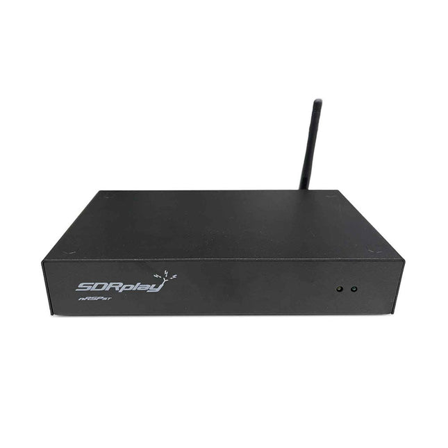
SDRplay SDRplay nRSP-ST Networked Radio Receiver (1 kHz to 2 GHz)
The nRSP-ST is a networked general coverage radio receiver for frequencies from 1 kHz to 2 GHz with up to 10 MHz of spectrum visibility. The nRSP-ST is your own personal remotely accessible SDR which can also be shared with a small number of trusted friends or colleagues. The nRSP-ST addresses the needs of radio enthusiasts who want a 'plug-and-play' solution for remote reception. As well as achieving this, we have addressed typical internet bandwidth limitations with the creation of a novel IQ Lite mode, which efficiently delivers channels of IQ data. We are also introducing the ability to control and store IQ recordings at the remote location. The nRSP-ST is ideal for anyone wanting a wideband remote receiver without needing computer skills and hours of set-up time and ongoing maintenance at the remote location. Features "Plug and play" integrated, networked general coverage receiver: Combines a receiver, a host computer and a whole lot more – all in one box! Apply power and connect to the internet (Ethernet or Wi-Fi) and the nRSP-ST is automatically accessible from anywhere Multi-platform SDRconnectTM software supports local operation or remote access on Windows, MacOS or Linux platforms The nRSP-ST & SDRconnect are configurable for available network bandwidth: In Full IQ mode, the nRSP-ST provides IQ data transfer of the visible spectrum bandwidth (e.g. for high-speed LAN or superfast internet connectivity) In IQ Lite mode, the nRSP-ST provides IQ data of channels up to 192 kHz wide (e.g. for digital decoding by the client) In Compact mode the nRSP-ST provides compressed audio (ideal for slower internet connections) Supports multiple client connections with a simultaneous mixture of connection modes – an admin tool allows you to assign usernames and timeouts to trusted friends or colleagues. All modes support visualization of up to 10 MHz spectrum bandwidth Two remote connection options: Use a remote SDRconnect client or Use the built-in web-server for remote access from any web browsing capable device, including Android/iOS tablets and phones The nRSP-ST offers the ability to record IQ and audio files to a NAS (network attached storage) device if available on the LAN. The 14-bit ADC full featured wideband SDR receiver covers all frequencies from 1 kHz through VLF, LF, MW, HF, VHF, UHF and L-band to 2 GHz, with no gaps Remotely monitor up to 10 MHz of spectrum at a time from a choice of 3 antennas Flash upgradable for future feature enhancements Included 1x nRSP-ST Receiver 1x WLAN antenna 1x Power supply 1x Manual Downloads Release notes Software
€ 554,18
-
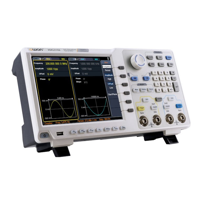
OWON OWON XDG3102 2-ch Arbitrary Waveform Generator (100 MHz)
Features Advanced DDS technology, up to 250 MHz frequency output 1.25 GS/s sampling rate, and 1 μHz frequency resolution Up to 1M arbitrary waveform length Vertical resolution: 14 bits Comprehensive waveform output: 6 groups waveforms, and 152 group built-in arbitrary waveforms Comprehensive modulation options: AM, FM, PM, FSK, 3FSK, 4FSK, PSK, OSK, ASK, BPSK, PWM, sweep, and burst High-accuracy frequency counter integrated, ranging from 100MHz till 200MHz SCPI and LabVIEW supported 8-inch 800 x 600 pixels touch screen LCD Specifications XDG3102 Channel 2 Frequency Output 100MHz Sample Rate 1.25GSa/s Vertical Resolution 14 bits Waveform Standard Waveform sine, square, pulse, ramp, noise, and harmonic Arbitrary Waveform exponential rise, exponential fall, sin(x)/x, step wave, and others, total of 150 built-in waveforms, and user-defined arbitrary waveform Frequency (resolution 1μHz) Sine 1μHz - 100MHz Square 1μHz - 40MHz Pulse 1μHz - 25MHz Ramp 1μHz - 5MHz Harmonic 1μHz - 50MHz Noise 120MHz (-3dB, typical) Arbitrary Waveform built-in waveform: 1uHz - 15MHzuser-defined waveform: 1uHz - 50MHz Accuracy ±1ppm, 0°C - 40°C Amplitude Amplitude (50Ω) 1mVpp - 10Vpp (≤40MHz); 1mVpp - 5Vpp (≤80MHz) 1mVpp - 2.5Vpp (≤120MHz); 1mVpp - 1Vpp (≤250MHz) Amplitude(high impedance) 2mVpp - 20Vpp (≤40MHz); 2mVpp - 10Vpp (≤80MHz); 2mVpp - 5Vpp (≤120MHz); 2mVpp - 2Vpp (≤250MHz) Resolution 1mV or 4 digits DC Offset Range (50Ω) ±(5 Vpk - Amplitude Vpp/2) Range (high-Z, open circuit) ±(10 Vpk - Amplitude Vpp/2) Accuracy ±(1% of |setting| + 1mV + Amplitude Vpp x 0.5%) Resolution 1mV or 4 digits Load Impedance 50Ω (typical) Accuracy ±(1% of setting + 1 mVpp) (typical, 1kHz sine, 0V offset) Sine Wave Spectrum Purity Harmonic Distortion Typical (0dB) DC - 1MHz: <-65dBc 1MHz - 10MHz: <-60dBc 10MHz - 120MHz: <-50dBc 120MHz - 200MHz: <-45dBc Total Harmonic Distortion <0.05 %, 10 Hz to 20 kHz, 1 Vpp Spurious (non-harmonic), Typical (0dB) ≤10MHz: <-70dBc >10MHz: <-70dBc + 6dB/ octave Phase Noise Typical (0 dBm, 10 kHz deviation) 10MHz: ≤-110dBc/Hz Square Rise/Fall Time <5ns Overshoot <3% Duty Cycle 50.0% (fixed) Jitter (rms) 300ps + 100ppm Pulse Pulse Width 12ns - 996875s Leading/Trailing Edge Time ≧7ns Overshoot <3% Jitter (rms) 300ps + 100ppm Ramp Linearity ≤1% of peak output (typical, 1kHz, 1 Vpp, 50% symmetry) Symmetry 0% to 100% Harmonic Harmonic Order ≤16 Harmonic Type even, odd, all, user Harmonic Amplitude could be set for all the harmonics Harmonic Phase Arbitrary Waveform Length 2 points - 1M points Vertical Resolution 14 bits Minimum Rise/Fall Time <7ns Jitter (rms) 3ns Modulation Type AM, FM, PM, PWM, FSK, 3FSK, 4FSK, PSK, OSK, ASK, BPSK, sweep, and burst AM Carrier Waveform sine, square, ramp, and arbitrary (except DC) Source internal / external Modulating Waveform sine, square, ramp, noise, and arbitrary Depth 0.0% - 100.0% Modulating Frequency 2 mHz - 100 kHz FM Carrier Waveform sine, square, ramp, and arbitrary (except DC) Source internal / external Modulating Waveform sine, square, ramp, noise, and arbitrary Modulating Frequency 2 mHz - 100 kHz PM Carrier Waveform sine, square, ramp, and arbitrary (except DC) Source internal / external Modulating Waveform sine, square, ramp, noise, and arbitrary Phase Deviation 0° - 180° Modulating Frequency 2 mHz - 100 kHz PWM Carrier Waveform pulse Source internal / external Modulating Waveform sine, square, ramp, noise, and arbitrary Width Deviation 0 ~ minimum (pulse duty ratio, 100% - pulse duty ratio) Modulating Frequency 2 mHz - 100 kHz FSK / 3FSK / 4FSK Carrier Waveform sine, square, ramp, and arbitrary (except DC) Source internal / external Modulating Waveform square with 50% duty cycle Key Frequency 2 mHz - 1MHz PSK Carrier Waveform sine, square, ramp, and arbitrary (except DC) Source internal / external Modulating Waveform square with 50% duty cycle Key Frequency 2 mHz - 1MHz OSK Carrier Waveform sine, square, ramp, and arbitrary (except DC) Source internal Oscillation Time square with 50% duty cycle Key Frequency 2 mHz - 1MHz ASK Carrier Waveform sine, square, ramp, and arbitrary (except DC) Source internal / external Modulating Waveform square with 50% duty cycle Key Frequency 2 mHz - 1MHz BPSK Carrier Waveform sine, square, ramp, and arbitrary (except DC) Source internal Modulating Waveform square with 50% duty cycle Key Frequency 2 mHz - 1MHz Sweep Carrier Waveform sine, square, ramp, and arbitrary (except DC) Type linear, and log Direction up, and down Sweep Time 1 ms to 500s, ± 0.1% Trigger Source internal, external, and manual Burst Carrier Waveform sine, square, ramp, pulse, and arbitrary (except DC) Burst Count 1 to 50,000 period, infinite, gating Internal Period 10 ns - 500 s Gated Source external trigger Frequency Counter Function frequency period, +width, -width, +duty, and -duty Frequency Range 100 MHz - 200 MHz Frequency Resolution 7 digits Input / Output Display 8”800 x 600 pixels touch screen LCD Type frequency counter, external modulation input,external trigger input,external reference clock input / output Communication Interface USB Host, USB Device, and LAN Dimension 340 x 177 x 90 mm Weight 2.50 kg
€ 650,00
-

Elektor November/December 2025 (EN)
Elektor GREEN and GOLD members can download their digital edition here. Not a member yet? Click here. Relio v1.0 - Presence Detection and Remote ControlA Matter-Enabled Smart Controller for AC Appliances Designing Better PCBsA Practical Guide for Professionals and Makers KiCad 9Top New and Updated Features Precision Picoammeter (1)With Curve Tracer Functionality Down to the pA range! Christmas Star 2025A Star Is Soldered 100 mV Continuity Tester Who’s Pushing the Boundaries of European Electronics?Companies to Watch productronica 2025: What’s New in Electronics Development and Production Automation to Tackle Reshoring Manufacturing, Tariffs and Labour Shortages Beyond Future ProofCircularity in Electronics Passive ComponentsLow-Loss Inductors Enabling High-Efficiency DC/DC Converters How Desktop Manufacturing Machines Are Democratizing PCB Production Starting Out in Electronics...Needs Power UHD Displays Driven with EaseYour Guide to Easily Put Various TFT-LCDs Into Operation Quickly Soldering in 2025Practical Soldering Tips Straight from the Workbench SimulIDEAn All-in-One Tool for Circuit Prototyping 2025: An AI OdysseyFrom Autocomplete to Colleague Wordy Christmas TreeA Festive Electronics Project with a Linguistic Twist Err-lectronicsCorrections, Updates, and Readers’ Letters Analog Pipeline DistortionA Cool Audio Effect For Guitars and Other Instruments ESP32 Audio Transceiver Board (Part 3)Stereo Transmission and Dual Radio
€ 14,90
-

OWON OWON XDG2035 2-ch Arbitrary Waveform Generator (35 Mhz)
The 2-channel OWON XDG2035 is a function/waveform generator that can generate signals with a maximum frequency of 35 Hz. The generator has a resolution of 1 µHz and a sample rate of 500 MSa/s. The OWON XDG2035 is capable of generating 6 standard waveforms and 150 arbitrary waveforms. With the included software you can write advanced functions up to 10 million points. Waveforms can be saved to the function generator's internal memory using a PC via USB or LAN. The OWON XDG2035 also supports SCPI commands and LabView. The function generator has an integrated high-quality frequency counter, which can operate from 100 to 200 MHz. Features Max. 35 MHz frequency output 500 MSa/s Sample rate, Vertical resolution 1μHz 14 bits Vertical Resolution, 10 Marb waveform length Comprehensive waveform output: 6 basic waveforms,and 150 built-in arbitrary waveforms Comprehensive modulation functions: AM, FM, PM, FSK, 3FSK, 4FSK, PSK, OSK, ASK, BPSK, PWM, Sweep, and Burst High-accuracy frequency counter integrated, supported range 100-200 MHz SCPI and LabVIEW supported 7 inch multi-touch screen (800 x 480 pixels) Specifications Channel 2 Frequency Output 35 MHz Sample Rate 500 MSa/s Vertical Resolution 14 bits Waveform Standard Waveform sine, square, pulse, ramp, noise, and harmonic Arbitrary Waveform exponential rise, exponential fall, sin(x)/x, step wave, and others, total 150 built-in waveforms, and user-defined arbitrary waveform Frequency (resolution 1 μHz) Sine 1 μHz-100 MHz Square 1 μHz ~ 30 MHz Pulse 1 μHz ~ 25 MHz Ramp 1 μHz ~ 3 MHz Noise (-3 dB, typical) 100 MHz Arbitrary Waveform 1 μHz ~ 15 MHz Harmonic 1 μHz ~ 50 MHz Accuracy ±2ppm, 25°C ±5°C Waveform Length 2 points - 10M points Amplitude Into 50Ω load 1mVpp ~ 10Vpp (≤25 MHz); 1mVpp ~ 5Vpp (≤60 MHz); 1mVpp ~ 2.5Vpp (≤100 MHz) Modulation Type AM, DSB-AM, FM, PM, ASK, FSK, PSK, BPSK, QPSK, 3FSK, 4FSK, OSK, PWM, SUM Frequency Counter Function Frequency, period, +width, -width, +duty, and -duty Frequency Range 100 ~ 200 MHz Frequency Resolution 7 digits Input/Output Input mode frequency counter, external modulation input, external trigger input, internal clock output, external reference clock input/output Communication Interface USB Host, USB Device, LAN, RS232 (optional) Mechanical specifications Dimensions 340 x 177 x 90 mm Weight 2.3 kg Included 1x OWON XDG2035 1x Power Cord 1x CD-ROM 1x Quick start guide 1x USB Cable 1x BNC-BNC Cable Downloads Quick Guide
€ 339,00
-
Elektor Digital Microcontroller Basics (E-book)
Microcontrollers have become an indispensable part of modern electronics. They make things possible that vastly exceed what could be done previously. Innumerable applications show that almost nothing is impossible. There’s thus every reason to learn more about them, but that raises the question of where to find a good introduction to this fascinating technology. The answer is easy: this Microcontroller Basics book, combined with the 89S8252 Flash Board project published by Elektor Electronics. However, this book offers more than just a basic introduction. It clearly explains the technology using various microcontroller circuits and programs written in several different programming languages. Three microcontrollers from the 8051 family are used in the sample applications, ranging from the simple 89C2051 to the AN2131, which is designed to support USB applications. The programming tools include assemblers, Basic-52 and BASCOM-51, and several C compilers. Every reader can thus find the programming environment most suitable to his or her needs. In the course of the book, the reader gradually develops increased competence in converting his or her ideas into microcontroller circuitry. All of the sample programs can be downloaded from the Elektor Electronics website or the author’s website. That has the added advantage that the latest versions are always available.
€ 19,95
Members: € 17,96
-

Elektor Digital Linux PC-based Measurement Electronics (E-book)
This book is intended as a highly-practical guide for Hobbyists, Engineers and Scientists wishing to build measurement and control systems to be controlled by a local or remote Personal Computer running the Linux operating system. Both hardware and software aspects of designing typical embedded systems are covered in detail with schematics, code listings and full descriptions. Numerous examples have been designed to show clearly how straightforward it can be to create the interfaces between digital and analog electronics, with programming techniques for creating control software for both local and remote systems. Hardware developers will appreciate the variety of circuits, including a novel, low cost modulated wireless link and will discover how using Matlab® overcomes the need for specialist programming skills. Software developers will appreciate how a better understanding of circuits plus the freedom offered by Linux to directly control at the register level enables them to optimize related programs. There is no need to buy special equipment or expensive software tools in order to create embedded projects covered in this book. You can build such quality systems quickly using popular low-cost electronic components and free distributed or low-cost software tools. Some knowledge of basic electronics plus the very basics of C programming only is required. Many projects in this book are developed using Matlab® being a very popular worldwide computational tool for research in engineering and science. The book provides a detailed description of how to combine the power of Matlab® with practical electronics. With an emphasis on learning by doing, readers are encouraged by examples to program with ease; the book provides clear guidelines as to the appropriate programming techniques “on the fly”. Complete and well-documented source code is provided for all projects. If you want to learn how to quickly build Linux-based applications able to collect, process and display data on a PC from various analog and digital sensors, how to control circuitry attached to a computer, then even how to pass data via a network or control your embedded system wirelessly and more – then this is the book for you! Features of this Book Use the power, flexibility and control offered only by a Linux operating system on a PC. Use a free, distributed downloadable GNU C compiler Use (optional) a low-cost Student Version of Matlab®. Use low-cost electronic sub-assemblies for projects. Improve your skills in electronics, programming, networking and wireless design. A full chapter is dedicated to controlling your sound card for audio input and output purposes. Program sound using OSS and ALSA. Learn how to combine electronic circuits, software, networks and wireless technologies in the complete embedded system.
€ 29,95
Members: € 26,96


