Products
-
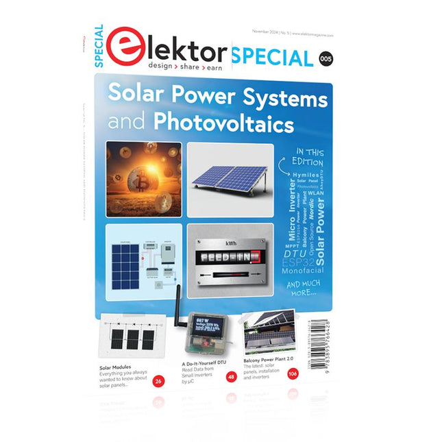
Elektor Special: Solar Power Systems and Photovoltaics
As demand for solar panel installation has risen sharply, especially for installations larger than balcony power plants, the order books of solar companies are full. If you ask for a quote today, you may have to wait a while, if your request isn't simply postponed indefinitely. Another consequence of the solar boom is that some companies are charging very high prices for installations. Yet there is an obvious and radical solution to the problem of excessive prices: Do it yourself, as the English say. The price of materials is currently affordable, and it's the ideal time for those who do the work themselves. They couldn't save more. Add to this the satisfaction of doing something useful, both economically and ecologically, and the pleasure of building yourself. In this special issue, you'll find a wide selection of Elektor assemblies, from solar panel controllers to solar water heaters and solar panel orientation systems. The issue also contains practical information on solar panel installation and the technology behind them. Finally, there are a number of articles on the subject of balcony power plants, from how to install them to how to connect them to the Internet... Contents BASICS Dimensioning Photovoltaic Panel ArraysAn introduction to photovoltaic energy and the commonest techniques,followed by simplified calculation models and setup guidelines. Light Sensor TechnologyMeasuring daylight using LEDs. Solar Power Made SimpleSolar charging with and without a controller. Cable Cross-sections and Energy Losses in Solar SystemsKey considerations on the minimum values to respect for electricalcurrent in solar panel cabling. Solar ModulesEverything you always wanted to know about solar panels... Ideal Diode ControllerDiode Circuits with Low Power Dissipation. TIPS Tracking for Solar Modules zBot Solar/Battery Power Supply Solar Cell Array Charger with Regulator Solar Cell Voltage Regulator Solar-Powered Night Light Alternative Solar Battery Charger PROJECTS Energy LoggerMeasuring and Recording Power Consumption. Tiny Solar SupplySunlight In, 3.3 V Out. A Do-It-Yourself DTURead Data from Small Inverters by μC. Solar ChargerPortable energy for people on the move. Solar Thermal Energy RegulatorMaximum power point tracking explored. 2-amp Maximum Power Tracking ChargerSolar Power To The Max. Computer-driven HeliostatFollow the sun or the stars. Garden LightingUsing solar cells. Solar Panel Voltage Converter for IoT DevicesYes we CAN exploit indoor lighting. Travel ChargerFree power in the mountains. Solar Cell Battery Charger/MonitorWith protection against deep discharge. Solar-powered Battery ChargerPIC12C671 avoids overcharging and deep charging. Converters for Photovoltaic PanelsContributed by TME (Transfer MultisortElektronik). Solar Charging RegulatorFor panels up to 53 watts. Solar-Powered ChargerFor lead-acid batteries. CAN Bus + Arduino for Solar PV Cell MonitoringDetect and locate serviceable panels in large arrays. Balcony Power Plant 2.0The latest: solar panels, installation and inverters
€ 19,95
Members: € 17,96
-
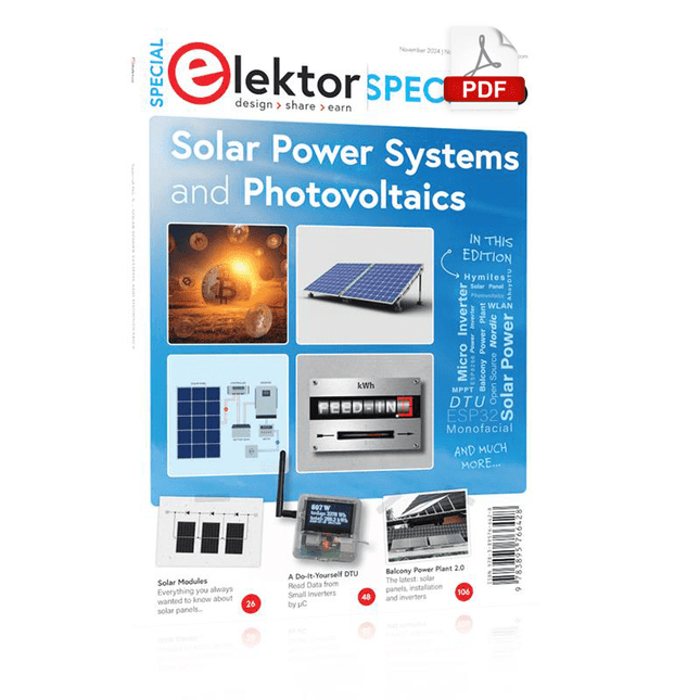
Elektor Digital Elektor Special: Solar Power Systems and Photovoltaics (PDF)
As demand for solar panel installation has risen sharply, especially for installations larger than balcony power plants, the order books of solar companies are full. If you ask for a quote today, you may have to wait a while, if your request isn't simply postponed indefinitely. Another consequence of the solar boom is that some companies are charging very high prices for installations. Yet there is an obvious and radical solution to the problem of excessive prices: Do it yourself, as the English say. The price of materials is currently affordable, and it's the ideal time for those who do the work themselves. They couldn't save more. Add to this the satisfaction of doing something useful, both economically and ecologically, and the pleasure of building yourself. In this special issue, you'll find a wide selection of Elektor assemblies, from solar panel controllers to solar water heaters and solar panel orientation systems. The issue also contains practical information on solar panel installation and the technology behind them. Finally, there are a number of articles on the subject of balcony power plants, from how to install them to how to connect them to the Internet... Contents BASICS Dimensioning Photovoltaic Panel ArraysAn introduction to photovoltaic energy and the commonest techniques,followed by simplified calculation models and setup guidelines. Light Sensor TechnologyMeasuring daylight using LEDs. Solar Power Made SimpleSolar charging with and without a controller. Cable Cross-sections and Energy Losses in Solar SystemsKey considerations on the minimum values to respect for electricalcurrent in solar panel cabling. Solar ModulesEverything you always wanted to know about solar panels... Ideal Diode ControllerDiode Circuits with Low Power Dissipation. TIPS Tracking for Solar Modules zBot Solar/Battery Power Supply Solar Cell Array Charger with Regulator Solar Cell Voltage Regulator Solar-Powered Night Light Alternative Solar Battery Charger PROJECTS Energy LoggerMeasuring and Recording Power Consumption. Tiny Solar SupplySunlight In, 3.3 V Out. A Do-It-Yourself DTURead Data from Small Inverters by μC. Solar ChargerPortable energy for people on the move. Solar Thermal Energy RegulatorMaximum power point tracking explored. 2-amp Maximum Power Tracking ChargerSolar Power To The Max. Computer-driven HeliostatFollow the sun or the stars. Garden LightingUsing solar cells. Solar Panel Voltage Converter for IoT DevicesYes we CAN exploit indoor lighting. Travel ChargerFree power in the mountains. Solar Cell Battery Charger/MonitorWith protection against deep discharge. Solar-powered Battery ChargerPIC12C671 avoids overcharging and deep charging. Converters for Photovoltaic PanelsContributed by TME (Transfer MultisortElektronik). Solar Charging RegulatorFor panels up to 53 watts. Solar-Powered ChargerFor lead-acid batteries. CAN Bus + Arduino for Solar PV Cell MonitoringDetect and locate serviceable panels in large arrays. Balcony Power Plant 2.0The latest: solar panels, installation and inverters
€ 14,95
Members: € 13,46
-

Elektor Digital Elektor Summer Circuits 2022 PDF (EN)
Over 50 Circuits & Projects US-Style Siren Two Rotary Encoders on One Analog Input How to Build a Digital 220-V AC Dimmer with Arduino Current Source for LEDs Detect Four Switches with 1 Pin Tiny On/Off Switch with Battery Level Check DIY Hand Sanitizer Dispenser A Simple Electronic Organ Ultra-Simple Stereo Amplifier Sound Activated Switch for Amplifiers Balanced/Unbalanced Converter External Mains Filter Button-Free Door Control DI Box for a Smartphone Fun With Running Lights One-Button Thyristor Control Quasi-Analog Exposure Timer for the Dark Room Circuits Galore From the Hackster.io Community Analog Tanning Timer Yet Another Single-Wire LCD Interface Simple AVR ATtiny13-Based PWM Generator Second Life for Batteries Touch Switch for LED Lights Tester for LEDs and DIP Switches Go/No-Go IR Control Tester Power Semiconductor Tester SPI for WS2812(B) LEDs Measuring Power Inductors One Plug for Raspberry Pi and Audio DAC DIY Test Fixture for the LCR Meter Arduino Ammeter Two-Finger Organ Low Noise ADC Calibrator DC/DC Boost Converter Two Potentiometers on One Digital Input Acoustic Proximity Sensor Battery-Free Radiator Sensor A Circuit for Detecting Bugs and Wireless Cameras Car Interior Light Timer Candle Simulator Digital Kitchen Timer Milliohm Meter Hot Water Production Delay Timer Simple Charger for 2S 18650 Cells Tiny Frequency Reference Low-Power IR Switch Recycle Your Car’s Telephone Charger Microphone Pre-Amp for Arduino DIY EMI Filters Electronic Dice Without an MCU Finger Capacitor A Self-Charging LED Flasher Also in this edition KiCad 6 – Five Features to Consider Flashback – The Elektor SC/MP Computer Interview – Making Art with Electricity My First PCB – Going Head First Into KiCad Minimizing Hardware with Smart Software Infographics – Facts and Figures New Devices from Analog Flashback – The Elektor Metal Detector Hexadoku – The Original Elektorized Sudoku
€ 7,50
-
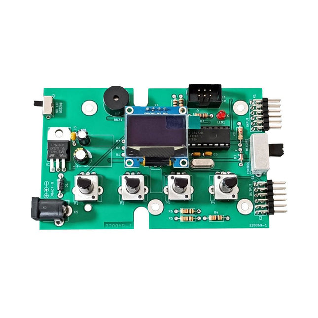
Elektor Labs Elektor Super Servo Tester Kit
The Elektor Super Servo Tester can control servos and measure servo signals. It can test up to four servo channels at the same time. The Super Servo Tester comes as a kit. All the parts required to assemble the Super Servo Tester are included in the kit. Assembling the kit requires basic soldering skills. The microcontroller is already programmed. The Super Servo Tester features two operating modes: Control/Manual and Measure/Inputs. In Control/Manual mode the Super Servo Tester generates control signals on its outputs for up to four servos or for the flight controller or ESC. The signals are controlled by the four potentiometers. In Measure/Inputs the Super Servo Tester measures the servo signals connected to its inputs. These signals may come from for instance an ESC, a flight controller, or the receiver or another device. The signals are also routed to the outputs to control the servos or the flight controller or ESC. The results are shown on the display. Specifications Operating modes Control/Manual & Measure/Inputs Channels 3 Servo signal inputs 4 Servo signal outputs 4 Alarm Buzzer & LED Display 0.96' OLED (128 x 32 pixels) Input voltage on K5 7-12 VDC Input voltage on K1 5-7.5 VDC Input current 30 mA (9 VDC on K5, nothing connected to K1 and K2) Dimensions 113 x 66 x 25 mm Weight 60 g Included Resistors (0.25 W) R1, R3 1 kΩ, 5% R2, R4, R5, R6, R7, R9, R10 10 kΩ, 5% R8 22 Ω, 5% P1, P2, P3, P4 10 kΩ, lin/B, vertical potentiometer Capacitors C1 100 µF 16 V C2 10 µF 25 V C3, C4, C7 100 nF C5, C6 22 pF Semiconductors D1 1N5817 D2 LM385Z-2.5 D3 BZX79-C5V1 IC1 7805 IC2 ATmega328P-PU, programmed LED1 LED, 3 mm, red T1 2N7000 Miscellaneous BUZ1 Piezo buzzer with oscillator K1, K2 2-row, 12-way pinheader, 90° K5 Barrel jack K4 1-row, 4-way pin socket K3 2-row, 6-way boxed pinheader S1 Slide switch DPDT S2 Slide switch SPDT X1 Crystal, 16 MHz 28-way DIP socket for IC2 Elektor PCB OLED display, 0.96', 128 x 32 pixels, 4-pin I²C interface Links Elektor Magazine Elektor Labs
€ 59,95€ 49,95
Best Price
-

Elektor Digital Embedded in Embedded (E-book)
ARM Cortex-M Embedded Design from 0 to 1 Hobbyists can mash together amazing functional systems using platforms like Arduino or Raspberry Pi, but it is imperative that engineers and product designers understand the foundational knowledge of embedded design. There are very few resources available that describe the thinking, strategies, and processes to take an idea through hardware design and low-level driver development, and successfully build a complete embedded system. Many engineers end up learning the hard way, or never really learn at all. ARM processors are essentially ubiquitous in embedded systems. Design engineers building novel devices must understand the fundamentals of these systems and be able to break down large, complicated ideas into manageable pieces. Successful product development means traversing a huge amount of documentation to understand how to accomplish what you need, then put everything together to create a robust system that will reliably operate and be maintainable for years to come. This book is a case study in embedded design including discussion of the hardware, processor initialization, low‑level driver development, and application interface design for a product. Though we describe this through a specific application of a Cortex-M3 development board, our mission is to help the reader build foundational skills critical to being an excellent product developer. The completed development board is available to maximize the impact of this book, and the working platform that you create can then be used as a base for further development and learning. The Embedded in Embedded program is about teaching fundamental skill sets to help engineers build a solid foundation of knowledge that can be applied in any design environment. With nearly 20 years of experience in the industry, the author communicates the critical skill development that is demanded by companies and essential to successful design. This book is as much about building a great design process, critical thinking, and even social considerations important to developers as it is about technical hardware and firmware design. Downloads EiE Software Archive (200 MB) IAR ARM 8.10.1 (Recommended IDE version to use) (1.2 GB) IAR ARM 7.20.1 (Optional IDE version to use) (600 MB)
€ 44,95
Members: € 40,46
-
Elektor Digital Embedded Operating System (E-book)
History and Future in the Internet of Things This book thoroughly reviews the history of the development of embedded Operating Systems, covers the technical characteristics, historic facts, as well as background business stories of mainstream embedded Operating Systems, and analyzes the technical evolution, market development, and new opportunities of embedded Operating Systems in the age of the Internet of Things. From the perspective of time, the book examines the evolution of critical technical aspects, including real-time and Power Management of embedded Operating Systems and Linux, Internet of Things security, communication, and cloud computing. The book looks into applications of embedded Operating Systems with important markets of mobile phones, communication equipment, automobile, and wearable devices, and also discusses business model and the issue of intellectual property of embedded Operating Systems. In addition, the book walks through the status quo, technical features, product evaluation and background of the Internet of Things Operating Systems in the second half of the book.
€ 29,95
Members: € 26,96
-

Elektor Digital ESP32 & ESP8266 Compilation (EN) | E-book
The ESP8266 from Espressif is a Wi-Fi microchip with full TCP/IP stack and microcontroller capability. It has made waves in the maker community with its low price. But many developers were unhappy with ESP8266's high power consumption. The ESP32, equipped with a ULP (Ultra Low Power) coprocessor, offers a remedy for this. This e-book features a number of projects featuring ESP32 & ESP8266 as well as an interview with the CEO of Espressif Teo Swee Ann. Articles ESP32 for Use in Industry 4.0 Equipment Scrolling Message Display, 512 LEDs controlled over Wi-Fi via an ESP-12F The Connected Greenhouse IoT demonstration project using MQTT and Node-RED VFD-tube Clock with ESP32 with an accurate Internet-derived time ESP32 Low Power DCF77 Emulator with ESP8266 ESP8266 on the Elektor Android I/O Board The Reason Behind the Hugely Popular ESP8266? Wi-Fi Desktop Thermostat Timers for the Wi-Fi Desktop Thermostat PlatformIO, the Universal Programming Tool Weather Display, Visualize current weather data on an LC display GoNotify, a Flexible IoT Sensor Interface ESP32 for Power Users USB Programming Adaptor for ESP8266 Getting started with ESP32 and the Arduino IDE MicroPython, Python for small systems RGBDigit Clock WLAN for Microcontrollers Return of the Wi-Fi Controller Board Compact and Self-contained WLAN
€ 9,95
Members: € 8,96
-

Elektor Publishing ESP32 by Example
A Project-Based Introduction to Microcontrollers and Drone Control A Practical Introduction to Embedded Systems with the ESP32 This book is intended for readers who are new to embedded systems and looking for a structured, example-driven way to begin. If you’ve explored general-purpose electronics or Arduino-based resources but found them too broad or lacking in practical application, this guide offers a more focused alternative. With a small, affordable set of components – such as LEDs, sensors, an OLED screen and a motion sensor – you’ll build and work with the same hardware setup throughout the book. This allows you to focus on learning and experimenting without constant reconfiguration. Topics include: Understanding and programming the ESP32 microcontroller Using the Arduino IDE to write and deploy code Exploring cyber-physical systems, culminating in basic drone control No prior experience with Arduino or embedded development is required. Each section includes hands-on examples and mini-projects designed to reinforce core concepts and encourage deeper exploration. By the end, you’ll be equipped not only to reproduce the book’s examples, but also to extend them toward your own ideas and applications. Whether your interest is in learning embedded programming, building interactive systems, or exploring educational drone control, this book provides a clear and practical path to getting started.
€ 44,95
Members: € 40,46
-

Elektor Digital ESP32 by Example (E-book)
A Project-Based Introduction to Microcontrollers and Drone Control A Practical Introduction to Embedded Systems with the ESP32 This book is intended for readers who are new to embedded systems and looking for a structured, example-driven way to begin. If you’ve explored general-purpose electronics or Arduino-based resources but found them too broad or lacking in practical application, this guide offers a more focused alternative. With a small, affordable set of components – such as LEDs, sensors, an OLED screen and a motion sensor – you’ll build and work with the same hardware setup throughout the book. This allows you to focus on learning and experimenting without constant reconfiguration. Topics include: Understanding and programming the ESP32 microcontroller Using the Arduino IDE to write and deploy code Exploring cyber-physical systems, culminating in basic drone control No prior experience with Arduino or embedded development is required. Each section includes hands-on examples and mini-projects designed to reinforce core concepts and encourage deeper exploration. By the end, you’ll be equipped not only to reproduce the book’s examples, but also to extend them toward your own ideas and applications. Whether your interest is in learning embedded programming, building interactive systems, or exploring educational drone control, this book provides a clear and practical path to getting started.
€ 34,95
Members: € 31,46
-

Elektor Academy Pro ESP32 by Example (Learning Course)
Complete ESP32 microcontroller learning course featuring a custom-designed MCU expansion board, hands-on projects, and a comprehensive online guide – perfect for learning hardware, programming, and connectivity step by step. A Practical Introduction to Embedded Systems with the ESP32 This course is designed for readers who are new to embedded systems and looking for a structured, example-driven way to get started. If you’ve explored general-purpose electronics or Arduino-based materials but found them too broad or lacking in practical guidance, this course offers a more focused alternative. Using the "ESP32 by Example Kit" (EEK) – a compact and affordable set of components featuring LEDs, sensors, an OLED display, and a motion processor – you’ll work with a consistent hardware setup throughout the course. Once assembled, the EEK stays mostly unchanged, allowing you to concentrate on learning and experimentation without constant reconfiguration. Topics include: Understanding and programming the ESP32 microcontroller Writing and deploying code with the Arduino IDE Exploring cyber-physical systems, culminating in basic drone control No prior experience with Arduino or embedded development is required. Each section features hands-on examples and mini-projects designed to reinforce key concepts and inspire deeper exploration. By the end of the course, you’ll be able not only to reproduce the book’s examples but also to build on them with your own ideas and applications. Whether you're interested in embedded programming, interactive systems, or introductory drone control, this course provides a clear and practical path to getting started. What you'll learn? Embedded programming with the ESP32 using the Arduino IDE Real-time sensor input and control via buttons, LEDs, and displays Gesture-based interaction using the MPU6050 motion sensor Bluetooth gamepad integration and drone control simulation Wi-Fi and UDP networking, local web servers, and NTP MQTT communication with cloud platforms like AWS and Arduino IoT How to build and deploy full-featured IoT systems Perfect for Students and self-learners exploring embedded systems Makers and IoT enthusiasts looking to improve their hardware skills Educators and trainers seeking ready-to-teach material Developers moving beyond Raspberry Pi or Arduino basics Support when you need it Access to instructors via Elektor Academy Helpful community forums and essential documentation What's inside the Box (Course)? New 384-page book: "ESP32 by Example" (valued at €45) Elektor ESP32 by Example Kit (EEK): Microcontroller Extension Board with 6 LEDs and 6 Buttons installed + OLED Display, MPU6050 3-axis Accelerometer and Gyroscope Module (valued at €40) Adafruit HUZZAH32 – ESP32 Feather MCU Board (valued at €30) ESP32 Cheap Yellow Display Board (valued at €25) DHT11 Humidity & Temperature Sensor Breadboard Jumper wires USB-C cable Access to the full course on the Elektor Academy Pro Learning Platform Instructional videos Downloadable Arduino project files for every module Learning Material (of this Box/Course) ▶ Click here to open Module 1 – Getting Started with the ESP32 & EEK Module 2 – Digital Output – LEDs and GPIO Module 3 – Switches and Input Handling Module 4 – EEK and PWM Module 5 – OLED and Display Output Module 6 – Motion Sensing with the MPU6050 Module 7 – Capstone Project (EEK in Action) Module 8 – WiFi and Web Control with ESP32 Module 9 – Cloud Concepts using EEK Module 10 – Hands-on: Arduino IoT Cloud and EEK Module 11 – BlueTooth and EEK GamePad Integration Module 12 – Why Drones? Module 13 – Drone Simulator Concepts Module 14 – Simple Drone Flight Control Module 15 – Real-Time Drone Flight Control Module 16 – Drone Control Mini-Projects Module 17 – Middleware and Python Scripting Module 18 – Python Applications for Drone Control Module 19 – Capstone EEK Control Project and Presentation About the Author Dr. Jim Solderitsch is an educator, software architect, systems developer, and cybersecurity researcher with a focus on cyber-physical systems. He currently serves as an Adjunct Professor in Computing Sciences at Villanova University in Pennsylvania. What is Elektor Academy Pro? Elektor Academy Pro delivers specialized learning solutions designed for professionals, engineering teams, and technical experts in the electronics and embedded systems industry. It enables individuals and organizations to expand their practical knowledge, enhance their skills, and stay ahead of the curve through high-quality resources and hands-on training tools. From real-world projects and expert-led courses to in-depth technical insights, Elektor empowers engineers to tackle today’s electronics and embedded systems challenges. Our educational offerings include Academy Books, Pro Boxes, Webinars, Conferences, and industry-focused B2B magazines – all created with professional development in mind. Whether you're an engineer, R&D specialist, or technical decision-maker, Elektor Academy Pro bridges the gap between theory and practice, helping you master emerging technologies and drive innovation within your organization.
€ 269,00€ 219,00
Best Price
-

Elektor Academy Pro ESP32 with Arduino C/C++ (Programming Course)
This complete ESP32 microcontroller programming course features a textbook, a component kit, hands-on projects, and a comprehensive online course with simulations. It is ideal for step-by-step learning of embedded systems programming with Arduino using a practical, hands-on approach. A Practical Introduction to Embedded Systems with the ESP32 This course is designed for people who are new to embedded systems and looking for a structured, example-driven way to get started. A kit of parts comprising LEDs and resistors, switches, sensors and actuators, displays, a breadboard and wires, and more is included. These are used in the course to illustrate example applications. No prior experience with Arduino or embedded development is required. Each section features hands-on examples and mini projects designed to reinforce key concepts and inspire deeper exploration. By the end of the course, you’ll be able not only to reproduce the examples but also to build on them with your own ideas and applications. What Will You Learn? Microcontroller programming with the ESP32 using the Arduino IDE Working with Digital I/O, read buttons and encoders, control LEDs and relays Read analog inputs, voltages, and analog sensors Generating analog output signals and PWM Use serial communication like UART, I²C and SPI to control displays and read digital sensors and SD cards Managing time Working with interrupts Real-time sensor input and control via buttons, LEDs, and displays Control actuators like relays and servo motors Who Is It For? Students and self-learners exploring embedded systems Makers and IoT enthusiasts looking to improve their hardware skills Educators and trainers seeking ready-to-teach material What's Inside the Box? Access to the full course on the Elektor Academy Pro Learning Platform ESP32 microcontroller board + USB cable Book: Programming Microcontrollers in C/C++ Using Arduino Downloadable project files for every module Component Box: 2× LED, red, 5 mm LED, green, 5 mm 3× Resistor, 470 Ω, 0.25 W LDR Potentiometer, 10 kΩ, linear Pushbutton Rotary encoder module Relay module DHT22 Humidity & Temperature Sensor TM1637-compatible 4-digit 7-segment display MPU-6050 IMU with headers SSD1306-compatible I²C OLED display Micro SD card adapter with header Buzzer SG90 Micro Servo ILI9341-compatible SPI 240×320 TFT display 20× Jumper wires Breadboard All Programming Courses (and differences in content) Course Arduino Raspberry Pi Pico with Arduino C/C++ ESP32 with Arduino C/C++ Raspberry Pi Pico with MicroPython ESP32 with MicroPython Online Course Access to Arduino Course Access to Pico with Arduino C/C++ Course Access to ESP32 with Arduino C/C++ Course Access to Pico with MicroPython Course Access to ESP32 with MicroPython Course Board Uno R3 Raspberry Pi Pico ESP32 Raspberry Pi Pico ESP32 Book Programming Microcontrollers in C/C++ Using Arduino Programming Microcontrollers in C/C++ Using Arduino Programming Microcontrollers in C/C++ Using Arduino Programming Microcontrollers in MicroPython Programming Microcontrollers in MicroPython Kit 40-piece Component Box 40-piece Component Box 40-piece Component Box 40-piece Component Box 40-piece Component Box
-

Elektor Academy Pro ESP32 with MicroPython (Programming Course)
This complete ESP32 microcontroller programming course features a textbook, a component kit, hands-on projects, and a comprehensive online course with simulations. It is ideal for step-by-step learning of embedded systems programming in MicroPython using a practical, hands-on approach. A Practical Introduction to Embedded Systems with the ESP32 This course is designed for people who are new to embedded systems and looking for a structured, example-driven way to get started. A kit of parts comprising LEDs and resistors, switches, sensors and actuators, displays, a breadboard and wires, and more is included. These are used in the course to illustrate example applications. No prior experience with Arduino or embedded development is required. Each section features hands-on examples and mini projects designed to reinforce key concepts and inspire deeper exploration. By the end of the course, you’ll be able not only to reproduce the examples but also to build on them with your own ideas and applications. What Will You Learn? Microcontroller programming in MicroPython with the ESP32 using the Thonny IDE Working with Digital I/O, read buttons and encoders, control LEDs and relays Read analog inputs, voltages, and analog sensors Generating analog output signals and PWM Use serial communication like UART, I²C and SPI to control displays and read digital sensors and SD cards Managing time Working with interrupts Real-time sensor input and control via buttons, LEDs, and displays Control actuators like relays and servo motors Who Is It For? Students and self-learners exploring embedded systems Makers and IoT enthusiasts looking to improve their hardware skills Educators and trainers seeking ready-to-teach material What's Inside the Box? Access to the full course on the Elektor Academy Pro Learning Platform ESP32 microcontroller board + USB cable Book: Programming Microcontrollers in MicroPython Downloadable project files for every module Component Box: 2× LED, red, 5 mm LED, green, 5 mm 3× Resistor, 470 Ω, 0.25 W LDR Potentiometer, 10 kΩ, linear Pushbutton Rotary encoder module Relay module DHT22 Humidity & Temperature Sensor TM1637-compatible 4-digit 7-segment display MPU-6050 IMU with headers SSD1306-compatible I²C OLED display Micro SD card adapter with header Buzzer SG90 Micro Servo ILI9341-compatible SPI 240×320 TFT display 20× Jumper wires Breadboard All Programming Courses (and differences in content) Course Arduino Raspberry Pi Pico with Arduino C/C++ ESP32 with Arduino C/C++ Raspberry Pi Pico with MicroPython ESP32 with MicroPython Online Course Access to Arduino Course Access to Pico with Arduino C/C++ Course Access to ESP32 with Arduino C/C++ Course Access to Pico with MicroPython Course Access to ESP32 with MicroPython Course Board Uno R3 Raspberry Pi Pico ESP32 Raspberry Pi Pico ESP32 Book Programming Microcontrollers in C/C++ Using Arduino Programming Microcontrollers in C/C++ Using Arduino Programming Microcontrollers in C/C++ Using Arduino Programming Microcontrollers in MicroPython Programming Microcontrollers in MicroPython Kit 40-piece Component Box 40-piece Component Box 40-piece Component Box 40-piece Component Box 40-piece Component Box
-
Elektor Digital ESP8266 and MicroPython (E-book)
Recently, the development of a tiny chip called the ESP8266 has made it possible to interface any type of microcontroller to a Wi-Fi AP. The ESP8266 is a low-cost tiny Wi-Fi chip having fully built-in TCP/IP stack and a 32-bit microcontroller unit. This chip, produced by Shanghai based Chinese manufacturer Espressif System, is IEEE 802.11 b/g/n Wi-Fi compatible with on-chip program and data memory, and general purpose input-output ports. Several manufacturers have incorporated the ESP8266 chip in their hardware products (e.g. ESP-xx, NodeMCU etc) and offer these products as a means of connecting a microcontroller system such as the Android, PIC microcontroller or others to a Wi-Fi. The ESP8266 is a low-power chip and costs only a few Dollars. ESP8266 and MicroPython – Coding Cool Stuff is an introduction to the ESP8266 chip and describes the features of this chip and shows how various firmware and programming languages such as the MicroPython can be uploaded to the chip. The main aim of the book is to teach the readers how to use the MicroPython programming language on ESP8266 based hardware, especially on the NodeMCU. Several interesting and useful projects are given in the e-book (pdf) to show how to use the MicroPython in NodeMCU type ESP8266 hardware: Project “What shall I wear today?”: You will be developing a weather information system using a NodeMCU development board together with a Text-to-Speech processor module. Project “The Temperature and Humidity on the Cloud”: You will be developing a system that will get the ambient temperature and humidity using a sensor and then store this data on the cloud so that it can be accessed from anywhere. Project “Remote Web Based Control”: You will be developing a system that will remotely control two LEDs connected to a NodeMCU development board using an HTTP Web Server application.
€ 29,95
Members: € 26,96
-

Elektor Publishing Experimenting with Red Pitaya STEMlab Gen 2
Practical Projects and Programs With Experimenting with Red Pitaya STEMlab Gen 2, Red Pitaya goes beyond a versatile board. It becomes a powerful laboratory instrument for precision measurement, analysis, and control. From the fundamentals of electronic project development, monitoring, control, and design to testing, this book walks you step-by-step through everything you need to know to harness the full potential of Red Pitaya hardware and software. The book presents real-time, FPGA-based projects that are developed on a PC using the Vivado environment, then transferred to the Red Pitaya for execution and testing. You will learn about enhanced performance, expanded I/O capabilities, improved FPGA features, and advanced connectivity options that open up new frontiers for precision measurement, monitoring, and control in your embedded applications. Inside the book you will discover: A deep dive into Red Pitaya architecture and hardware design Electronic experiments using Red Pitaya for measurement and monitoring Hands-on projects using the Python programming language Practical guidance for FPGA programming using Red Pitaya Red Pitaya FPGA projects using the Verilog HDL under Vivado IDE Practical design of electronic projects including measurement and testing Step-by-step examples that bridge theory and real-world implementation Whether you are designing your own electronic circuits, developing signal analysis tools, or creating real-time control or monitoring systems, this book provides you the knowledge and confidence you need to fully learn and customize the Red Pitaya platform.
€ 39,95€ 32,95
Best Price
-

Elektor Digital Experimenting with Red Pitaya STEMlab Gen 2 (E-book)
Practical Projects and Programs With Experimenting with Red Pitaya STEMlab Gen 2, Red Pitaya goes beyond a versatile board. It becomes a powerful laboratory instrument for precision measurement, analysis, and control. From the fundamentals of electronic project development, monitoring, control, and design to testing, this book walks you step-by-step through everything you need to know to harness the full potential of Red Pitaya hardware and software. The book presents real-time, FPGA-based projects that are developed on a PC using the Vivado environment, then transferred to the Red Pitaya for execution and testing. You will learn about enhanced performance, expanded I/O capabilities, improved FPGA features, and advanced connectivity options that open up new frontiers for precision measurement, monitoring, and control in your embedded applications. Inside the book you will discover: A deep dive into Red Pitaya architecture and hardware design Electronic experiments using Red Pitaya for measurement and monitoring Hands-on projects using the Python programming language Practical guidance for FPGA programming using Red Pitaya Red Pitaya FPGA projects using the Verilog HDL under Vivado IDE Practical design of electronic projects including measurement and testing Step-by-step examples that bridge theory and real-world implementation Whether you are designing your own electronic circuits, developing signal analysis tools, or creating real-time control or monitoring systems, this book provides you the knowledge and confidence you need to fully learn and customize the Red Pitaya platform.
€ 32,95
Members: € 29,66
-
Elektor Digital Experiments with Digital Electronics (E-book)
The field of digital electronics is central to modern technology. This e-book presents fundamental circuits using gates, flip-flops and counters from the CMOS 4000 Series. Each of the 50 experiments has a circuit diagram as well as a detailed illustration of the circuit’s construction on solderless breadboard. Learning these fundamentals is best done using practical experiments. Building these digital circuits will improve your knowledge and will be fun to boot. Many of the circuits presented here have practical real-life applications. With a good overview of the field, you’ll be well equipped to find simple and cost-effective solutions for any application. The e-book is targeted essentially at students, trainees and anyone with an interest in and requiring an introduction to digital control electronics. Moreover, the knowledge gleaned here is the foundation for further projects in the field of microcontrollers and programming.
€ 24,95
Members: € 22,46
-

Elektor Digital Explore ATtiny Microcontrollers using C and Assembly Language (E-book)
AVR Architecture and Programming An in-depth look at the 8-bit AVR architecture found in ATtiny and ATmega microcontrollers, mainly from a software and programming point of view. Explore the AVR architecture using C and assembly language in Microchip Studio (formerly Atmel Studio) with ATtiny microcontrollers. Learn the details of how AVR microcontrollers work internally, including the internal registers and memory map of ATtiny devices. Program ATtiny microcontrollers using an Atmel-ICE programmer/debugger, or use a cheap hobby programmer, or even an Arduino Uno as a programmer. Most code examples can be run using the Microchip Studio AVR simulator. Learn to write programs for ATtiny microcontrollers in assembly language. See how assembly language is converted to machine code instructions by the assembler program. Find out how programs written in the C programming language end up as assembly language and finally as machine code instructions. Use the Microchip Studio debugger in combination with a hardware USB programmer/debugger to test assembly and C language programs, or use the Microchip Studio AVR simulator. DIP packaged ATtiny microcontrollers are used in this volume for easy use on electronic breadboards, targeting mainly the ATtiny13(A) and ATtiny25/45/85. Learn about instruction timing and clocks in AVR microcontrollers using ATtiny devices. Be on your way to becoming an AVR expert with advanced debugging and programming skills.
€ 34,95
Members: € 31,46
-

Elektor Digital Explore the Raspberry Pi in 45 Electronics Projects (3rd Edition | E-book)
3rd Edition – Fully updated for Raspberry Pi 4 The Raspberry Pi is a very cheap but complete computer system that allows all sorts of electronics parts and extensions to be connected. This book addresses one of the strongest aspects of the Raspberry Pi: the ability to combine hands-on electronics and programming. Combine hands-on electronics and programming After a short introduction to the Raspberry Pi you proceed with installing the required software. The SD card that can be purchased in conjunction with this book contains everything to get started with the Raspberry Pi. At the side of the (optional) Windows PC, software is used which is free for downloading. The book continues with a concise introduction to the Linux operating system, after which you start programming in Bash, Python 3 and Javascript. Although the emphasis is on Python, the coverage is brief and to the point in all cases – just enabling you to grasp the essence of all projects and start adapting them to your requirements. All set, you can carry on with fun projects. The book is ideal for self-study No fewer than 45 exciting and compelling projects are discussed and elaborated in detail. From a flashing lights to driving an electromotor; from processing and generating analog signals to a lux meter and a temperature control. We also move to more complex projects like a motor speed controller, a web server with CGI, client-server applications and Xwindows programs. Each project has details of the way it got designed that way The process of reading, building, and programming not only provides insight into the Raspberry Pi, Python, and the electronic parts used, but also enables you to modify or extend the projects any way you like. Also, feel free to combine several projects into a larger design.
€ 32,95
Members: € 29,66
-
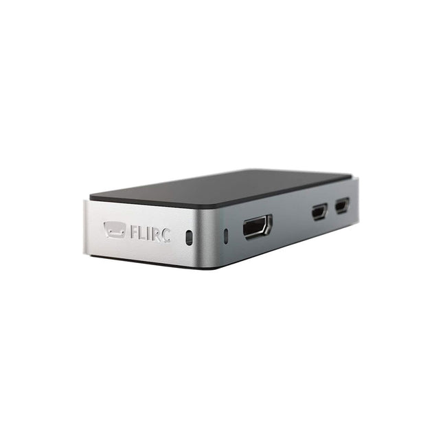
FLIRC FLIRC Case for Raspberry Pi Zero
The FLIRC Raspberry Pi Zero Case is compatible with Raspberry Pi Zero W and the newer Raspberry Pi Zero 2 W. The design of the FLIRC Zero Case is based on the original FLIRC case. As with the original, the aluminum housing serves as protection and, thanks to the contact point on the processor, as a passive cooler. Ideal for silent operation. In addition to a normal cover that encloses and protects the Raspberry Pi Zero, there is a second cover that allows access to the GPIO pins through a small opening.
-
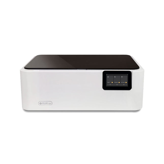
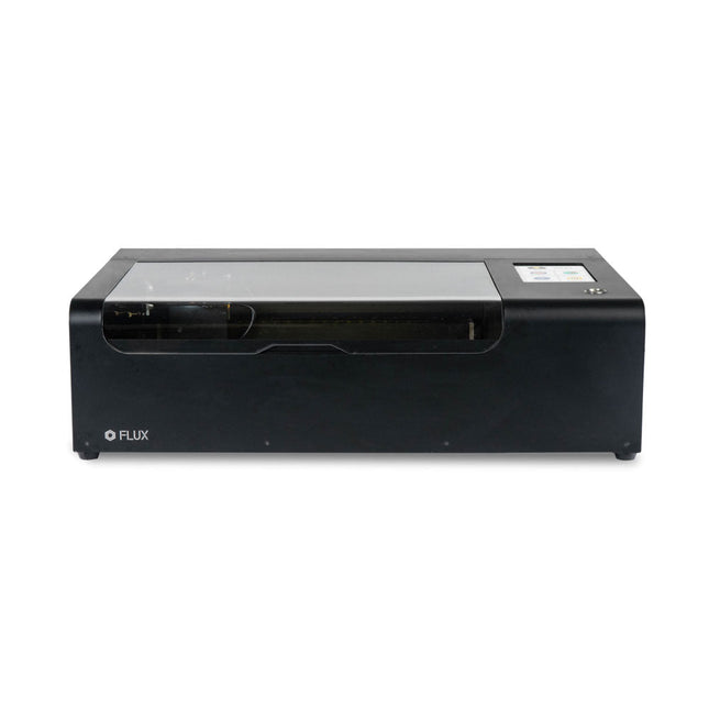
FLUX FLUX Ador Laser Cutter (20 W)
FLUX Ador is the world's first color printing laser cutter. Powered by three high-quality, interchangeable modules, Ador enables you to engrave and cut though a wide range of materials while enhancing your projects with a pop of color. New creative potential with Ador Whether you’re an educator, small business, crafter or designer, with Ador, the application boundary is for you to define. Easy to use Place material then autofocus Drag and drop your design Engrave, cut or print Project Completed! Big workspace, big ideas Ador offers a big working space of 430 x 300 mm, with a depth of 30 mm, expanding the horizons of your creativity. Specifications Dimensions 637 x 488 x 226 mm Weight 19 kg Work Area X&Y: 20 W Diode laser: 430 x 300 mm (X & Y varies with different modules)Z: 30 mm (for all modules) & 20 mm (with prism) Camera Preview Area Whole work area Voltage AC 110-240 V Touch Panel Yes, 8 inches (diagonal) Camera 8 MP I/O USB / WiFi Laser Spec W Diode laser Module Laser Moving Speed 0~400 mm/s Laser Cutting Thickness Varies for different materials Software Mode Vector / Graphic (monochrome, gray scale) Operating System Windows / macOS / Linux Software File Type JPG / PNG / SVG / DXF Included FLUX Ador 20 W diode laser module 6x prism lift Power adapter Power cord Hex key Vent Hose Vent hose Duct Clamp Wooden test piece Laser Cutter Lubricant Downloads Firmware
€ 1.935,00
Best Price
-
FLUX FLUX Beamo Laser Cutter
FLUX Beamo is a powerful and compact 30 W CO2 desktop laser cutter that can cut and engrave a range of materials including metals. With its easy-to-use design, intuitive controls and features, you can effortlessly create amazing things. Built-in HD camera Cutting and engraving is hassle-free with our preview mode. Place your material, preview the work area in the Beam Studio software and engrave. Your design comes out exactly as shown in the preview. Integrated safety features If left opened, auto pause ensures the laser stops. The internal water cooling system provides a stable cutting process. Plus, you can stop production with a single switch at any time. Powerful high resolution laser The Beamo ultra thin laser can engrave exceptional detail down to 0.05 mm wide with a clear resolution of 1,000 dpi. Fitting for any craft or small business project. The most precise compact CO2 laser engraver Beamo's sleek, modern and compact design fits beautifully in any home, school or workshop space. It comes pre-assembled with a metal body and acrylic lid, measuring 615 x 445 x 177 mm. Bring your designs to life with its 30 W CO2 laser operating on a 30 x 21 cm work area. Safe for home and school Beamo prioritises safety with its thoughtful design features. The machine is fully enclosed, and it automatically pauses if the lid is opened during a task. Additionally, there is a single switch for immediate machine shutdown in case of emergencies. Beamo is equipped with a Class 1 laser, which is completely safe under normal use. Specifications Dimensions 615 x 445 x 177 mm Weight 22 kg Work Area 300 x 210 x 45 mm (11.81 x 8,27 x 1.77') Camera Preview Area 300 x 195 mm Voltage AC 110 V / 220 V Touch Panel 1024 x 600 LCD Camera HD CMOS I/O Wi-Fi / Ethernet Laser Spec 30 W CO₂ Laser Laser Moving Speed 0~300 mm/s Laser Cutting Thickness 0-5 mm (varies by material) Software Mode Vector / Graphic (monochrome, gray scale) Operating System Windows / macOS / Linux Software File Type JPG / PNG / SVG / DXF Included FLUX Beamo (distilled water included) Vent hose Duct Clamp Double sided tape to align the mirror's Ethernet cable Vent Hose Double head wrench Wood piece Torx screwdriver and 2.5 mm hexagonal wrench Funnel 1x Laser Cutter Lubricant Power cord Wifi Dongle USB Beamo Manual Honey Comb Platform (30 W) Downloads Firmware
€ 2.660,00
Best Price
-
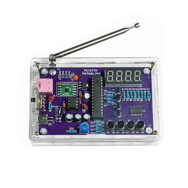
Generic FM Radio Kit
This DIY kit (HU-017A) is a wireless FM radio receiver with a 4-digit 7-segment display. It operates within the global FM receiving frequency band of 87.0-108.0 MHz, making it suitable for use in any country or region. The kit offers two power supply modes, allowing you to use it both at home and outdoors. This DIY electronic product will help you understand circuits and improve your soldering skills. Features 87.0-108.0 MHz FM Radio: Built-in RDA5807 FM data processor with a standard FM receiving frequency band. The FM frequency can be adjusted using the F+ and F- buttons. Adjustable Volume: Two volume adjustment methods – button and potentiometer. There are 15 volume levels. Active & Passive Audio Output: The kit has a built-in 0.5 W power amplifier to drive 8 Ω speakers directly. It also outputs audio signals to headsets or loudspeakers with AUX interfaces, allowing personal listening and sharing of FM audio. Configured with a 25 cm dedicated FM antenna and a (red) 4-digit 7-segment display for real-time display of FM radio frequency. The transparent acrylic shell protects the internal circuit board. It supports dual power supply methods – 5 V USB and 2x 1.5 V (AA) batteries. DIY Hand Soldering: The kit comes with various components that need to be installed manually. It helps exercise and improve soldering skills, making it suitable for electronics hobbyists, beginners, and educational purposes. Specifications Operating voltage DC 3 V/5 V Output impedance 8 Ω Output power 0.5 W Output channel Mono Receiver frequency 87.0 MHz~108.0 MHz Frequency accuracy 0.1 MHz Operating temperature −40°C to +85°C Operating humidity 5% to 95% RH Dimensions 107 x 70 x 23 mm IMPORTANT: Remove the batteries when powering the radio over to USB. Included 1x PCB 1x RDA5807M FM Receiver 1x STC15W404AS MCU 1x IC Socket 1x 74HC595D Register 1x TDA2822M Amplifier 1x IC Socket 1x AMS1117-3.3 V Voltage Converter 18x Metal Film Resistor 1x Potentiometer 4x Ceramic Capacitor 5x Electrolytic Capacitor 4x S8550 Transistor 1x Red LED 1x 4-digit 7-segment Display 1x Toggle Switch 1x SMD Micro USB Socket 1x Radio Antenna 1x AUX Audio Socket 4x Black Button 4x Button Cap 1x 0.5 W/8 Ω Speaker 1x Red/Black Wire 2x Double-sided adhesive 1x AA Battery Box 1x USB cable 6x Acrylic Board 4x Nylon Column Screw 4x M3 Screw 4x M3 Nut 4x M2x22 mm Screw 1x M2x6 mm Screw 5x M2 Nut
-
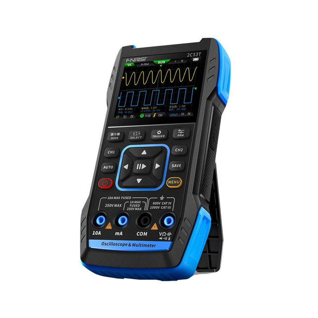
FNIRSI FNIRSI 2C53T Upgrade (3-in-1) 2-ch Oscilloscope (50 MHz) + Multimeter + Signal Generator
The updated FNIRSI 2C53T, an enhanced version of its 10 MHz predecessor, is a compact and versatile 3-in-1 device. It combines a dual-channel 50 MHz oscilloscope, a 4.5-digit True RMS multimeter, and a signal generator with 13 waveform types, making it an essential tool for maintenance and research professionals. Oscilloscope: Features 50 MHz bandwidth, 250 MS/s sampling rate, ±400 V protection, FPGA + ARM + ADC architecture, and waveform saving for analysis. Multimeter: 4.5-digit True RMS with 19999 counts, supports AC/DC voltage, current, capacitance, resistance, diode, and continuity measurements. Signal Generator: Outputs 13 signal types up to 50 KHz, with adjustable frequency, amplitude, and duty cycle. With a 2.8-inch LCD, 3000 mAh battery (6-hour runtime), and a portable design, it delivers powerful functionality in a user-friendly package. Specifications Oscilloscope Channels 2 Analog Bandwidth 50 MHz Real-time Sampling Rate 250 MS/s Storage Depth 1 Kpts Impedance 1 MΩ Time Base Range 10ns-20s Vertical Sensitivity 10 mV/div-10 V/div (x1) Maximum Measured Voltage ±400 V Trigger Mode Auto/Normal/Single Trigger Type Rising edge, Falling edge Display Mode Y-T/Rolling/X-Y Coupling Method AC/DC Persistence OFF, 500ms, 1s, ∞ Math 8 Basic Operations + FFT Supported Waveform Screenshot Save, Export Waveform Image, Cursor Measurement, Infinite Afterglow Multimeter DC Voltage 1.9999V/19.999V/199.99V/1000V ±(0.5%+3) AC Voltage 1.9999V/19.999V/199.99V/750.0V ±(1%+3) DC Current 19.999mA/199.99mA/1.9999A/9.999A ±(1.2%+3) AC Current 19.999mA/199.99mA/1.9999A/9.999A ±(1.5%+3) Resistance 19.999MΩ/1.9999MΩ/199.99KΩ/19.999KΩ ±(0.5%+3) 1.9999KΩ/199.99Ω ±(2.0%+3) Capacitance 999.9uF/99.99uF/9.999uF/999.9nF/99.99nF/9.999nF ±(2.0%+5) 9.999mF/99.99mF ±(5.0%+20) Temperature −55~1300°C (−67~2372°F) ±(2.5%+5) Continuity Test Yes Diode Yes Signal Generator 13 Signal Waveforms Sine wave, rectangular wave, sawtooth wave, half wave, full wave, positive step wave, reverse step wave, exponential rise, exponential fall, DC, multi-audio, Sinker pulse, Lorentz wave Output Frequency 0-50 KHz Output Amplitude 0-3 V Output Duty Cycle 0-100% General Display 2.8" HD color screen Resolution 320 x 240 Charging USB-C (5 V/1 A) Battery 3000 mAh Lithium battery Standby Time 6 hours Languages English, Chinese Dimensions 167 x 89 x 35 mm Weight 300 g Differences New vs Old Version Model 2C53T Upgrade 2C53T Predecessor Bandwidth 50 MHz 10 MHz Display Mode Y-T/Rolling/X-Y Y-T/Rolling Math 8 Basic Operations + FFT N/A Cursor Function Yes N/A XY Lissau Graph Yes N/A Afterglow Function Yes N/A Multimeter Accuracy 19999 Counts 9999 Counts Signal Generator 50 KHz 2 MHz Included 1x FNIRSI 2C53T Upgrade Oscilloscope (50 MHz) 2x P6100 Oscilloscope probes (10X) 1x Multimeter probe 1x Alligator clip probe 1x USB-C charging cable 1x Storage bag 1x Manual Downloads Manual Firmware V1.0.3
€ 119,95€ 94,95
Best Price
-

FNIRSI FNIRSI 2D15P (3-in-1) 2-ch Oscilloscope (100 MHz) + Multimeter + Signal Generator
The FNIRSI 2D15P is a compact 3-in-1 test tool combining a 2-channel digital oscilloscope, True RMS multimeter, and waveform generator in one device. With a 4.3" capacitive touchscreen, 100 MHz bandwidth, 500 MSa/s sampling rate, and up to 1,200 fps capture speed, it’s ideal for fast troubleshooting, signal analysis, and electronics testing. Features Dual-Channel Input (100 MHz single-channel, 50 MHz dual-channel operation) Selectable Memory Depths 20 MHz Bandwidth Limit Grayscale & Color Temperature Visualization Math Operations (Add, Subtract, Multiply, Divide, etc.) XY Mode & Infinite Persistence Cursor Function & 13 Auto Measurements Auto / Normal / Single Trigger Modes True RMS Multimeter (19,999 Counts) 10 MHz DDS Signal Generator Specifications General Display 4.3" IPS Capacitive Touchscreen Operation Touch + Knob + Physical Buttons Charging USB-C (12 V/1 A fast charging) Battery 5000 mAh Lithium battery Dimensions 19.6 x 12.9 x 5.7 cm Weight 1.1 kg Oscilloscope Channels 2 Analog Bandwidth 100 MHz Sample Rate 500 MSa/s Memory Depth 10K, 100K, 1M Input Impedance 1 MΩ Timebase Range 5ns - 50s Vertical Sensitivity 10 mV - 10 V/div Max Input Voltage 800 V (x10 Probe) Trigger Mode Auto, Normal, Single Trigger Type Rising, Falling, Both Edges Coupling AC/DC Persistence min / 2s / 5s / 10s / 20s / 50s / ∞ Math Operations Yes Waveform Capture Yes Waveform Export Yes Cursor Measurement Yes Multimeter DC Voltage 1.9999V / 19.999V / 199.99V / 1000V AC Voltage 1.9999V / 19.999V / 199.99V / 750.0V DC Current 19.999mA / 199.99mA / 1.9999A / 9.999A AC Current 19.999mA / 199.99mA / 1.9999A / 9.999A Resistance 19.999MΩ / 1.9999MΩ / 199.99KΩ / 19.999KΩ / 1.9999KΩ / 199.99Ω Capacitance 999.9uF / 99.99uF / 9.999uF / 999.9nF / 99.99nF / 9.999nF / 9.999mF / 99.99mF Diode Yes Continuity Yes Signal Generator Channels 1 Frequency 0–10 MHz Amplitude 0.1–3.0 Vpp Duty Cycle 0–100% Included 1x FNIRSI 2D15P Oscilloscope 2x P6100 Oscilloscope Probes 1x Multimeter Probe 1x Alligator Clip Probe 1x USB Data Cable 1x Manual Downloads Manual Firmware V2.0.0.7
€ 209,00€ 179,95
Best Price


