Products
-
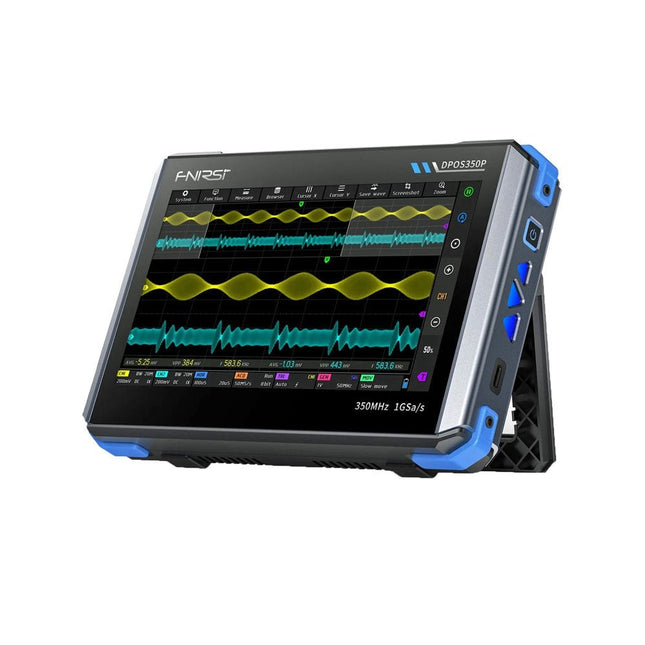
FNIRSI FNIRSI DPOS350P (4-in-1) 2-ch Tablet Oscilloscope (350 MHz) + Signal Generator + Frequency Response Analyzer + Spectrum Analyzer
2 Channels • 350 MHz • 1 GSa/s • 50,000 wfm/s • 7 inch Touchscreen The FNIRSI DPOS350P is a sleek 4-in-1 powerhouse in tablet form! This compact and portable device packs serious functionality: it combines a 2-channel oscilloscope (350 MHz), a signal generator (50 MHz), a frequency response analyzer (50 MHz), and a spectrum analyzer (200 kHz–350 MHz) – all in one unit. Whether you're in R&D, troubleshooting, or field testing, the DPOS350P delivers the tools you need to measure, generate, analyze, and visualize electronic signals with precision and clarity. Its responsive high-resolution touchscreen and intuitive controls make signal analysis fast, flexible and efficient. Features Powerful Multi-Function Integration 350 MHz 2-channel oscilloscope with 1 GSa/s real-time sampling 50 MHz signal generator with 14 standard + custom waveforms Spectrum analyzer (200 kHz–350 MHz): Perfect for EMI, RF & HF testing Frequency response analyzer (FRA) up to 50 MHz High-Performance Waveform Capture 50,000 wfm/s refresh rate for real-time signal clarity 350 MHz bandwidth (single-channel mode) Detects rare and low-probability anomalies Crisp Display & Smooth Operation 7" IPS touchscreen (1024 x 600 resolution) Switch between grayscale and color temperature display Easy to operate in various test environments Reliable, Protected & Fast-Charging High-voltage protection up to 400 V Fast charging with QC 18 W (full charge in 2 hours) Built for stable long-term operation Data Storage & Export Save up to 500 waveform records + 90 screenshots USB export for easy reporting and offline analysis Specifications General Display 7 inch (IPS full viewing angle) Resolution 1024 x 600 pixels Interaction mode Capacitive touch screen Total power consumption 10 W Power-on configuration 5 presets Charging QC 18 W, 12 V/1.5 A (USB-C) Battery 3.7 V, 8000 mAh lithium battery Battery life approx. 3 hours in operation, 5 hours standby Heat dissipation Air cooling Expansion interface USB data port Automatic shutdown 15~60 minutes / off Firmware upgrade Support .iso image upgrade Languages English / Portuguese / Russian / Chinese Dimensions 190 x 128 x 37 mm Oscilloscope Analog channels 2 Analog bandwidth 350 MHz Rise time 1ns Real-time sampling rate 1 GSa/s Memory depth 60 Kpts Input impedance 1 MΩ / 14PF Time base range 5ns ~ 50s Roll time base 50ms ~ 50s Vertical sensitivity 2 mV ~ 20 V (1X) Vertical range 16 mV ~ 160 V (1X) DC accuracy ±2% Time accuracy ±0.01% Input coupling DC / AC Probe attenuation 1X / 10X / 100X Hardware bandwidth limit 150M / 20M High resolution mode 8bit ~ 16bit Parameter measurements 12 types Cursor measurement Time, period, frequency, level, voltage Trigger detection Digital trigger Trigger channel CH1 / CH2 Trigger mode Auto / Single / Normal Trigger edge Rising edge / Falling edge Trigger suppression L1 ~ L3 Trigger level Manual / automatic 10% ~ 90% Screenshot storage 90 pictures Waveform storage 500 groups Background grid Display / hide Waveform movement Coarse adjustment / fine adjustment Overvoltage protection Withstand voltage 400 V Waveform brightness Adjustable Simple FFT display Yes Digital fluorescence Yes Color temperature display Yes X-Y mode Yes ZOOM time base Yes One-key automatic adjustment Yes One-key return to zero Yes Data browser Yes Signal Generator Waveform types 14 standard functions + captured waveform Frequency 0~50 MHz (sine wave only, other waveforms up to 10M/5M/3M) Amplitude 0~5 VPP Offset -2.5 V ~ +2.5V Duty cycle 0.1~99.9% Frequency resolution 1 Hz Amplitude resolution 1 mV Offset resolution 1 mV Duty cycle resolution 0.1% Customizable captured waveform 500 groups Frequency Response Analyzer (FRA) Excitation signal frequency 100 Hz ~ 50 MHz Excitation signal amplitude 0~5 VPP Excitation signal offset -2.5V ~ +2.5V Excitation frequency count 20~500 Cursor measurement Frequency / gain / phase Operating mode Single / cyclic System calibration Yes Spectrum Analyzer Conversion method FFT FFT length 4K ~ 32K Frequency range 200 KHz ~ 350 MHz Level range -60 dBmV ~ +260 dBmV Cursor measurement Frequency / amplitude Marking parameter Maximum energy harmonic Waterfall chart Yes 3D waterfall chart Yes Automatic adjustment Yes System calibration Yes Included 1x FNIRSI DPOS350P Oscilloscope (4-in-1) 2x 350 MHz Probes 1x QC 18 W Fast Charger (EU) 1x USB-C Cable 1x Alligator Clip 1x Storage Bag 1x Manual Downloads Manual Firmware
€ 309,00€ 259,00
Best Price
-
FNIRSI FNIRSI DPS150 DC Power Supply (150 W)
The FNIRSI DPS150 is a high-performance adjustable DC power supply that features a USB-C input interface and multiple power supply modes, allowing precise adjustment of output voltage (0-30 V) and current (0-5 A). It provides efficient, low-consumption, and stable output, equipped with multiple safety protection functions including overvoltage, overcurrent, overload, overheating, and reverse connection. It can be flexibly applied to serial connection of multiple devices, with rich and user-friendly display and operation, compact and portable design, meeting various application needs. Features 30 V, 5 A, 150 W variable DC power with 0.01 V, 0.001 A precision, CC/CV modes, and <20 mV ripple to protect sensitive electronics. Supports PC, QC, and DC inputs with programmable outputs and 6 preset voltage/current settings. Compatible with 4 mm banana plugs, U-shaped terminals, and copper wires for various equipment. 8 safety mechanisms including overvoltage, current, short circuit, and overheating protection. 2.8-inch HD IPS screen with 90° flip, numerical and curve displays for easy monitoring. Small, space-saving design for use in labs, repairs, and DIY projects. Specifications Input Voltage 5~32 V DC Input Current 100 mA-5 A Output Voltage 0-30 V Output Current 0~5 A Output Power 0-150 W Input Way PD fast charger QC fast charger Power bank DC power adapters Operating Environment 0-40°C Load Regulation 0.49% Full Load Efficiency 96.30% Display 2.8 inch (320 x 240) Dimensions 106 x 76 x 28 mm Weight 178 g Included 1x DPS150 Power Supply 2x Alligator clip wires (black & red) 1x Micro USB cable 1x Manual Downloads Manual Firmware V0.0.1
€ 59,00
-

FNIRSI FNIRSI DPS150PD DC Power Supply (150 W)
The FNIRSI DPS150 is a high-performance adjustable DC power supply that features a USB-C input interface and multiple power supply modes, allowing precise adjustment of output voltage (0-30 V) and current (0-5 A). It provides efficient, low-consumption, and stable output, equipped with multiple safety protection functions including overvoltage, overcurrent, overload, overheating, and reverse connection. It can be flexibly applied to serial connection of multiple devices, with rich and user-friendly display and operation, compact and portable design, meeting various application needs. Features 30 V, 5 A, 150 W variable DC power with 0.01 V, 0.001 A precision, CC/CV modes, and <20 mV ripple to protect sensitive electronics. Supports PC, QC, and DC inputs with programmable outputs and 6 preset voltage/current settings. Compatible with 4 mm banana plugs, U-shaped terminals, and copper wires for various equipment. 8 safety mechanisms including overvoltage, current, short circuit, and overheating protection. 2.8-inch HD IPS screen with 90° flip, numerical and curve displays for easy monitoring. Small, space-saving design for use in labs, repairs, and DIY projects. Specifications Input Voltage 5~32 V DC Input Current 100 mA-5 A Output Voltage 0-30 V Output Current 0~5 A Output Power 0-150 W Input Way PD fast charger QC fast charger Power bank DC power adapters Operating Environment 0-40°C Load Regulation 0.49% Full Load Efficiency 96.30% Display 2.8 inch (320 x 240) Dimensions 106 x 76 x 28 mm Weight 178 g Included 1x DPS150 Power Supply 2x Alligator clip wires (black & red) 1x C2C PD charging cable 1x 100 W PD GaN Adapter (EU) 1x Micro USB cable 1x Manual Downloads Manual Firmware V0.0.1
€ 95,00
-
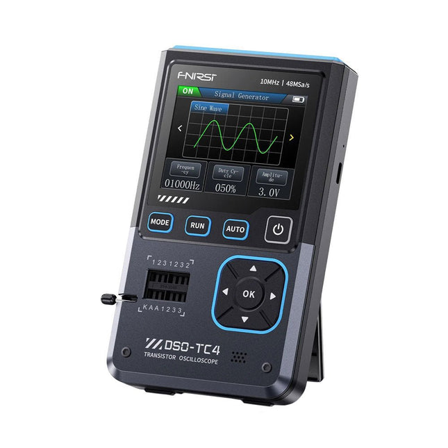
FNIRSI FNIRSI DSO-TC4 (3-in-1) Oscilloscope (10 MHz) + Transistor Tester + Signal Generator
The FNIRDSI DSO-TC4 is a multifunctional transistor oscilloscope that is both comprehensive and practical. It is designed for use in maintenance and R&D applications, integrating an oscilloscope, transistor tester, and signal generator into a single device. Features Equipped with a 2.8-inch TFT color screen for a clear and intuitive display Built-in high-capacity rechargeable lithium battery (1500 mAh) with a standby time of up to 4 hours Compact and lightweight, ideal for mobile use Specifications Oscilloscope Analog Bandwidth 10 MHz Real-Time Sampling Rate 48 MSa/s Input Impedance 1 MΩ Coupling Mode AC/DC Test Voltage Range 1:1 Probe: 80 Vpp (+40 V) 10:1 Probe: 800 Vpp (+400 V) Vertical Sensitivity 10 mV/div~10 V/div (X1 range) Vertical Displacement Adjustable with indication Time Base Range 50ns~20s Trigger Mode Auto/Normal/Single Trigger Type Rising edge, Falling edge Trigger Level Adjustable with indication Waveform Freeze Yes (HOLD function) Automatic Measurement Max, Min, Avg, RMS, Vpp, Frequency, Cycle, Duty Cycle Component Tester Transistor Amplification factor "hfe"; Base-Emitter voltage "Ube", Ic/Ie, Collector-Emitter reverse leakage current "Iceo", Ices, Forward voltage drop of protection diode "Uf" Diode Forward voltage drop <5 V (Forward voltage drop, Junction capacitance, Reverse leakage current) Zener Diode 0.01~32 V Reverse Breakdown Voltage (K-A-A Test Area) Field-Effect Transistor (FET) JFET: Gate capacitance "Cg", Drain current Id under "Vgs", Forward voltage drop of protection diode "Uf" IGBT: Drain current Id under Vgs, Forward voltage drop of protection diode Uf MIOSTET: Threshold voltage "Vt", Gate capacitance "Cg", Drain-Source resistance "Rds", Forward voltage drop of protection diode "Uf" Unidirectional SCR Trigger voltage <5V, Gate level (Gate voltage) Bidirectional SCR Trigger current <6mA (Gate voltage) Capacitor 25pF~100mF, Capacitance value, Loss factor "Vloss" Resistor 0.01Ω~50MΩ Inductor 10μH~1000μH, DC resistance DS18B20 Temperature sensor, Pins: GND, DQ, VDD DHT11 Temperature and humidity sensor, Pins: VDD, DATA, GND Signal Generator Output Waveform Supports 13 waveform outputs Waveform Frequency 0-50 KHz Square Wave Duty Cycle 0-100% Waveform Amplitude 0.1-3.0 V General Display 2.8-inch TFT color screen Backlight Brightness adjustable Power Supply USB-C (5 V/1 A) Battery 3.7 V/1500 mAh Languages English, German, Spanish, Portuguese, Russian, Chinese, Japanese, Korean Dimensions 90 x 142 x 27.5 mm Weight 186 g Included 1x FNIRSI DSO-TC4 (3-in-1) Oscilloscope (10 MHz) 1x P6100 Oscilloscope probes (10X) 1x Alligator clip probe 3x Test hooks 1x Adapter 1x USB-C charging cable 1x Manual Downloads Manual Firmware V0.0.7 (+V1.0.9)
€ 89,95€ 74,95
Best Price
-
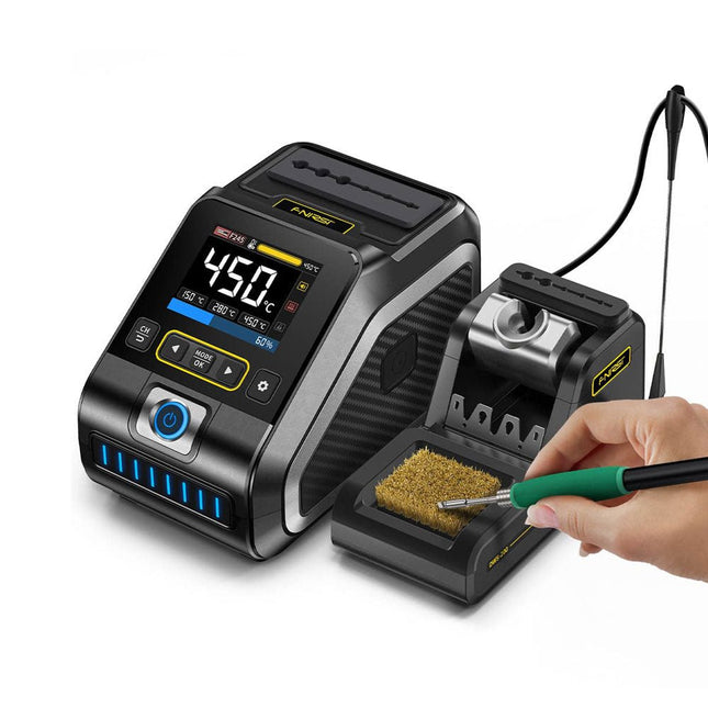
FNIRSI FNIRSI DWS-200 Smart Soldering Station (with F245 Handle + 6 Soldering Tips)
The FNIRSI DWS-200 is a powerful 200 W smart soldering station, ideal for electronic soldering applications. Powered by a switch-mode power supply, it operates smoothly with a wide voltage input range of 100-240 V. The station provides an adjustable temperature range from 100°C to 450°C (212°F to 842°F) and allows for easy switching between °C and °F. To enhance efficiency, it supports up to three preset temperature values and can connect to a soldering iron stand for standby mode activation. The station also features a dynamic temperature curve mode for real-time data monitoring, ensuring precise and consistent performance in demanding soldering tasks. Features Maximum power output of 200 W, allowing for fast heating Wide adaptive voltage input of 100-240 V 2.8" HD color TFT display with intelligent control Multiple preset groups to switch between different settings quickly Supports F245 and F210 soldering handle types, offering flexibility for different soldering applications Real-time sleep mode to extend the life of the soldering tip Multi-mode real-time monitoring for power and temperature status, enhancing safety and precision Specifications Peak Power 200 W (max) Temperature Range 100°C~450°C (212°F~842°F) Display 2.8" TFT HD Color Screen Heating Time 1 sec Melting Time 3 sec Input Voltage 100-240 V (AC) Input Fuse 3 A Soldering Handle Type F245 Dimensions (Station) 156 x 96 x 103 mm Weight (Station) 475 g Included 1x FNIRSI DWS-200 Soldering Station 1x Soldering Handle F245 6x Soldering Tips (B, KU, K, C2, I, JS) 1x Connecting Cable 2x Helping Hands 1x Power Cable (EU) Downloads Manual Firmware V1.3
€ 179,00
-

FNIRSI FNIRSI FNB58 USB Tester (with Bluetooth)
The FNIRSI FNB58 USB tester (with Bluetooth) is a comprehensive and very accurate USB voltage and current meter. It features a 2.0-inch full-color HD TFT display, built-in USB-A, micro USB and USB-C interface. With this device you can measure the power supply or power consumption of products or the charging power of cell phones and power supplies. You can also determine the fast charging protocol of chargers. Features USB-A and USB-C interface 2.0" HD display Data at a glance Wide compatibility Ultra-precise data detection Play with fast charging technology Automatic protocol detection (PD2.0, 3.0, 3.1, PPS, QC2.0, 3.0, FCP, SCP, AFC, PE, DASH VOOC, SuperVOOC and more) Simple user interface, easy to operate 4 function curve displays (real-time voltage and current curve, offline curve recording, D+/D- voltage curve, high-speed power supply ripple measurement) Cable detection 10 groups of energy recording battery capacity calculation PC connectivity for data logging and firmware updates Bluetooth app for Android devices Specifications Voltage range 4-28 V Current range 0-7 A Power range 0-120 W Load equivalent internal resistance 0-9999.9 Ω D+/D- voltage 0-3.3 V Capacity 0-9999.99 Ah Power consumption 0-9999.99 Wh Cable resistance 0-9999.9 Ω Interfaces micro USB, USB-A, USB-C Dimensions 42 x 13 x 82 mm Downloads Manual Firmware V0.68
€ 49,95
-

FNIRSI FNIRSI HRM-10 Battery Internal Resistance & Voltage Tester
The FNIRSI HRM-10 is a portable, high-precision battery internal resistance and voltage tester. This device offers true four-wire measurement and is designed for both accuracy and ease of use. It automatically measures internal resistance and voltage values simultaneously, displaying the results on its HD color screen. Users have the option to manually adjust voltage and resistance ranges to suit their needs. The device also includes a sorting mode that automatically filters the good and bad batteries based on user-set thresholds. Additionally, it supports the storage of historical data and allows for exporting measurement records in table format. Features High Measurement Accuracy Tabular Data Export Auto-Evaluate Measurement Results 8 Threshold Settings HD Color Screen Folding Stand 1000 mAh Lithium Battery Specifications Voltage Resistance Measuring range 0-100 V (DC) 0-200 Ω Accuracy ±0.5% ±0.5% Gear Automatic, 1 V, 10 V, 100 V Automatic, 20 mΩ, 200 mΩ, 2 Ω, 20 Ω, 200 Ω Instrument test signal frequency 1 Khz (AC) Rechargeable USB-C (5 V/1 A) Built-in battery 1000 mAh lithium battery User calibration Yes Sorting mode Yes History record Yes Recorded data export Yes Working environment –10°C to +45°C, relative humidity <80% Storage environment –20°C to +80°C, relative humidity <80% Dimensions 158.7 x 80.5 x 28.4 mm Weight 225 g Included 1x FNIRSI HRM-10 Internal Resistance Tester 1x Clip Test Line 1x USB-C data cable 1x Manual Downloads Manual Firmware V0.3
€ 49,95
-
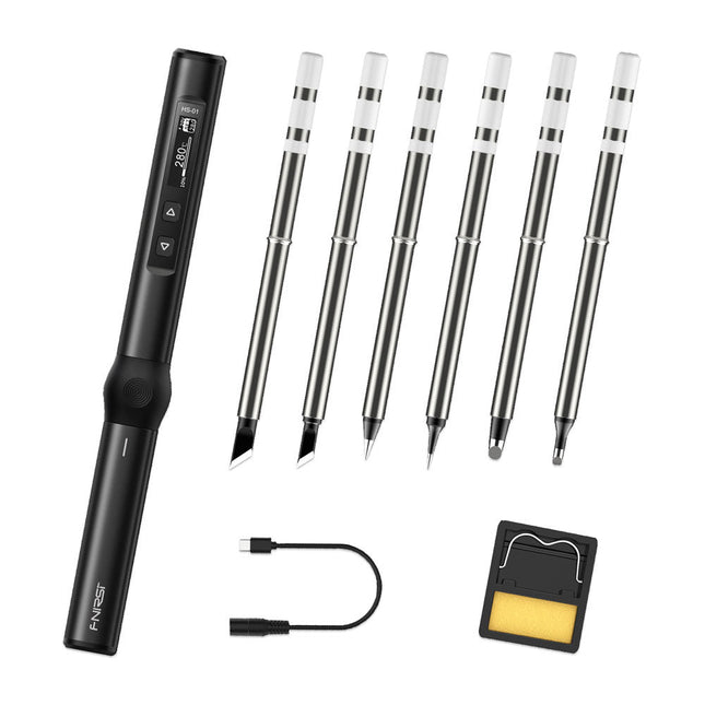
FNIRSI FNIRSI HS-01 Smart Soldering Iron (incl. 6 Soldering Tips)
The perfect tool for quick repairs The FNIRSI HS-01 is a powerful, adjustable smart soldering iron with a built-in 0.87-inch OLED display that quickly reaches temperatures between 80-420°C (180-780°F). The display shows all important information, including the status of the temperature level, the set temperature, the supply voltage and the power percentage. You can set the input voltage from 9-20 V directly in the menu according to your needs. The integrated sleep mode automatically turns off the iron after 30 minutes. Features 96 W input (DC) 65 W PD power OLED display Constant temperature & fast heating CNC metal integral molding Smart safety anti-scald Mini pocket size Ergonomic design Aluminum material Left/right hand switch Efficient heat radiation Inductive sleep Color: Black Specifications Power 65 W Screen 0.87" OLED Operating voltage 9-20 VDC Power supply USB-C Temperature range 80-420°C (180-780°F) Fast charging protocol PD trigger Dimensions 184 x 20 x 20 mm (7.24 x 0.79 x 0.79') Weight 56 g Power Selection Operating voltage 20 V 15 V 12 V 9 V Operating current ≥3.25 A ≥2.5 A ≥2 A ≥1.5 A Power 65 W 37.5 W 24 W 13.5 W Tin melting time 8s 12s 17s 30s Included 1x FNRISI HS-01 smart soldering iron 6x Soldering iron tips (HS01-BC2, HS01-KR, HS01-K65, HS01-B2, HS01-ILS, HS01-BC3) 1x DC to USB-C power cable 1x Mini soldering iron stand 1x Manual Required Power adapter USB-C cable Downloads Manual Firmware V0.3.s19
€ 82,00
-
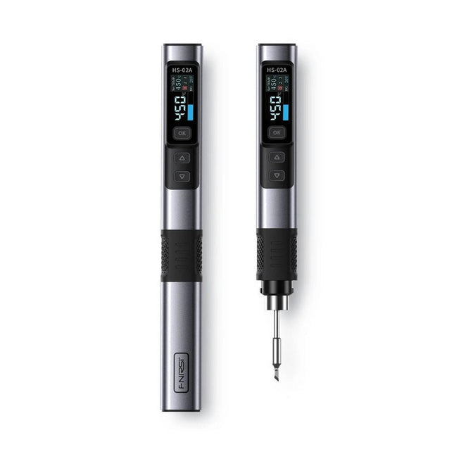
FNIRSI FNIRSI HS-02A Smart Soldering Iron (incl. 6 Soldering Tips)
The FNIRSI HS-02A is an improved version of the HS-01 soldering iron with a better grip and a shorter tip for more comfort and precision during use. It features a larger 0.96-inch IPS HD color display that allows for better visibility of settings and status. With an output power of 100 W, the HS-02A heats up quickly and reaches operating temperature in about 2 seconds. The temperature is adjustable in a range of 100-450°C (212-842°F) to meet different soldering requirements. Features Temperature: 100-450°C (212-842°F) Accurate temperature adjusting and control Fast heating CNC Metal Shell Adaptive Power 100 W High Power Protocols: PD, QC Specifications Temperature Range 100-450°C (212-842°F) Working Voltage 9-20 V Display 0.96" IPS HD Color Screen Power Supply USB-C Fast Charging Protocols PD / QC Power 100 W (max) Dimensions 180 x 20 mm Weight 61 g Included 1x FNRISI HS-02A Smart soldering iron 6x Soldering iron tips (HS02A-KU, HS02A-K, HS02A-JS, HS02A-I, HS02A-C2, HS02A-B) 1x Mini soldering iron stand 1x Manual Downloads Manual Firmware V1.7
€ 61,95
-

FNIRSI FNIRSI LC1020E High Precision LCR Meter
The FNIRSI LC1020E High-Precision LCR Meter with ESR tester is a portable and intelligent solution for testing electronic components, offering a basic accuracy of up to 0.3%. It is ideal for engineers, technicians, and makers. The device supports L/Q, C/D, and R/D measurements using both series and parallel equivalent circuit models, and features a 2.8-inch TFT color display. With preset thresholds and audio-visual alerts, it enables fast pass/fail evaluation, making it perfect for batch testing and quality control. Supporting test frequencies up to 100 kHz, it is well suited for high-frequency analysis of inductors, capacitors, and resistors. Features ±0.05% accuracy with 4.5-digit resolution Automatic R/L/C identification for fast measurements 5 test frequencies (100 Hz–100 kHz) & 3 voltage levels (0.1–0.6 V) Dual display: L/C/R/Z + X/D/Q/θ/ESR Sorting mode & bias voltage for batch testing Dual ports (3-/5-terminal) with 4-wire Kelvin support Data hold & logging for efficient workflow Compact, rechargeable (3000 mAh) – ideal for lab & field use Specifications General Test Frequency 100 Hz, 120 Hz, 1 kHz, 10 kHz, 100 kHz Basic Accuracy 0.3% Display 2.8-inch TFT LCD display Display Digits Main Parameter: 4.5 digits Secondary Parameter: 4.5 digits Measurement Parameters Main Parameters: AUTO/R/C/L/Z Secondary Parameters: X/D/Q/θ/ESR Measurement Range L: 0-100H C: 0-100mF R: 0-10M Internal Bias 0.0 V, 0.5 V Test Level 0.1 V, 0.3 V, 0.6 V Calibration Functions Open circuit calibration, Short circuit calibration Comparison Function Used to calculate the relative error between the component measurement value and the nominal value, displayed as a percentage, and provides filtering results. Nominal values and tolerance can be set, with tolerance range adjustable from 0.1% to 99.9% Function Record Checks if the measured component data meets the set nominal value and tolerance, recording the number of successful and failed measurements Test Terminal Configuration Three-terminal, Five-terminal Output Impedance 100Ω Interface USB-C (Virtual serial port) Others Language settings, Screen brightness, Sound settings, Auto power-off, Calibration settings, System information Battery 3000 mAh Lithium battery Dimensions 18.5 x 8.5 x 3.5 cm Weight 680 g Capacitance (C) Range: 1mF-100mF 100 Hz: 5% ±5 digits 1 kHz: 3% ±5 digits 10 kHz: / 100 kHz: / Range: 1uF-1mF 100 Hz: 1% ±4 digits 1 kHz: 0.5% ±5 digits 10 kHz: 2% ±5 digits 100 kHz: 3% ±4 digits Range: 1nF-1uF 100 Hz: / 1 kHz: 0.3% ±2 digits 10 kHz: 0.4% ±2 digits 100 kHz: 1% ±4 digits Range: 1pF-1nF 100 Hz: / 1 kHz: 2% ±2 digits 10 kHz: 1.5% ±2 digits 100 kHz: 2% ±4 digits Inductance (L) Range: 1H-100H 100 Hz: 2% ±5 digits 1 kHz: 2% ±5 digits 10 kHz: / 100 kHz: / Range: 1mH-1H 100 Hz: 0.4% ±5 digits 1 kHz: 0.3% ±2 digits 10 kHz: 0.4% ±3 digits 100 kHz: 2.5% ±5 digits Range: 10uH-1mH 100 Hz: 3% ±5 digits 1 kHz: 0.5% ±4 digits 10 kHz: 0.5% ±3 digits 100 kHz: 1.5% ±5 digits Range: 1uH-10uH 100 Hz: / 1 kHz: 2% ±5 digits 10 kHz: 2% ±5 digits 100 kHz: 4% ±5 digits Resistance (R) Range: 1MΩ-10MΩ 100 Hz: 5% ±4 digits 1 kHz: 3% ±3 digits 10 kHz: / 100 kHz: / Range: 1KΩ-1MΩ 100 Hz: 0.4% ±4 digits 1 kHz: 0.2% ±2 digits 10 kHz: 0.3% ±3 digits 100 kHz: 0.6% ±5 digits Range: 1Ω-1KΩ 100 Hz: 1.5% ±4 digits 1 kHz: 0.3% ±2 digits 10 kHz: 0.3% ±3 digits 100 kHz: 0.6% ±5 digits Range: 10mΩ-1Ω 100 Hz: 4% ±4 digits 1 kHz: 2% ±5 digits 10 kHz: 2% ±5 digits 100 kHz: 5% ±5 digits Included 1x FNIRSI LC1020E LCR Meter 1x Kelvin Test Clip 2x Test Leads (1x black, 1x red) 1x Shorting Plate 1x USB-C Cable 1x Manual Downloads Manual Firmware V1.1
€ 84,95€ 69,95
Best Price
-
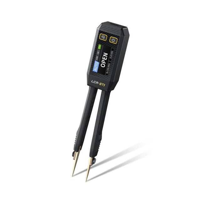
FNIRSI FNIRSI LCR-ST1 Smart SMD Tweezers (LCR/ESR Tester)
The FNIRSI LCR-ST1 is a compact, multifunctional, and smart LCR tester that supports automatic measurements of resistance, capacitance, inductance, diode testing, and continuity. Its 1.14-inch color display combined with a convenient magnetic adsorption function enhances ease of use, while the built-in 250 mAh lithium battery ensures long-lasting performance. The device supports three frequency ranges (100 Hz, 1 kHz and 10 kHz) and offers 0.3 V and 0.6 V RMS test levels for versatile testing applications. The unique tweezer-shaped design of the LCR-ST1 is ideal for delicate tasks in confined spaces and enables fast and accurate testing of electronic components. Its light weight and portable design make it an invaluable tool for both field and laboratory use. Whether you are an experienced engineer or just starting out in electronics, the LCR-ST1 delivers reliable and accurate measurement results, allowing you to complete your tasks with greater efficiency and precision. Features Offers 3 test frequencies (100 Hz, 1 kHz, 10 kHz) and 2 test voltage levels. Features automatic component identification for faster and more reliable measurements. High-resolution 1.14-inch color display for clear readouts. Supports automatic data recording and storage. The tweezer tips are made from gold-plated brass for enhanced durability and conductivity. Specifications Resistance Range 10 mΩ – 10 MΩ Capacitance Range 1 pF – 22 mF Inductance Range 1 μh – 10 H Diode On voltage 0.7 V Frequency Test 100 Hz, 1k Hz, 10 KHz Level Test 0.3 V, 0.6 V RMS Parameter Display ESR, D value, Q value, Z value, X value Display 1.14" HD color screen Charging Interface USB-C, 5 V/1 A Power Supply Built-in 250 mAh lithium battery Auto Recognition Measurement Yes Replaceable Tweezer Head Yes Auto Shutdown Yes Data Hold Yes History Record Connect to PC to view and export Dimensions 28 x 19 x 150 mm Weight 41 g Included 1x LCR-ST1 SMD Tweezers 2x Hook Tips 1x Magnetic Patch 1x USB cable 1x Tool bag 1x Manual Downloads Manual Firmware V1.6
€ 34,95
-

FNIRSI FNIRSI SG-003A Signal Generator
The FNIRSI SG-003A multi-functional Signal Generator a.k.a. Process Meter/Calibrator is a high-precision voltage/current generator and meter. The SG-003A provides highly accurate reference voltages or currents for testing and calibrating other measurement instruments like multimeters and oscilloscopes. Besides voltages and currents, the SG-003A also generates rectangular pulse signals with precisely programmable frequencies and duty cycles. Its converter mode turns the SG-003A into a precision voltage-controlled current source, or current-controlled voltage source, and even a voltage- or current-controlled frequency generator. The SG-003A is a great tool for checking your multimeter’s accuracy and precision, and for testing e.g. LEDs. Features Accuracy (voltage/current) 0.1% ±0.005 Resolution (current) 0.01 mA Frequency 0-10 kHz Resolution 5 digits Output power 24 V Display 2.4" TFT LCD (320 x 240) Dimensions 92 x 72 x 30 mm Weight 165 g Specifications Signal Range Precision Resolution Max load External power supply Active current output 0~24 mA ±(0.1% + 0.005) 0.01 mA 750 Ω Passive current output (XMT) 0~24 mA ±(0.1% + 0.005) 0.01 mA 0~30 V Voltage output 0~24 V ±(0.1% + 0.005) 0.01 V 24 V loop 0~24 mA ±(0.1% + 0.005) 0.01 mA Frequency output 0~9999 Hz ±2% 5 digits Current input 0~24 mA ±(0.1% + 0.005) 0.01 mA Voltage input 0~30 V ±(0.1% + 0.005) 0.01 V Included 1x FNIRSI SG-003A Signal generator 4x Test clips 1x USB charger 1x USB-C cable 1x Manual Downloads Manual Firmware V4.3
€ 69,95
-

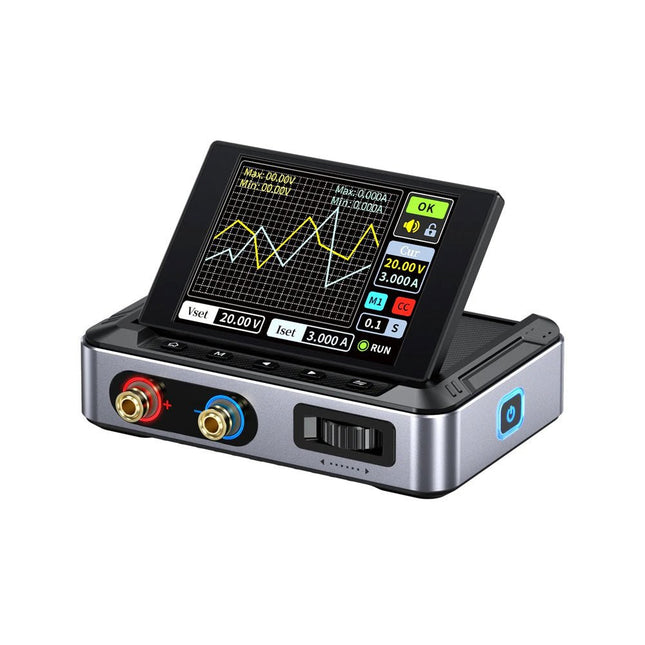
FNIRSI FNIRSI SWM-20 Dual-Pulse Spot Welder
The FNIRSI SWM-20 handheld spot welder is a high-efficiency, user-friendly, and easy-to-carry welding tool. It features dual-pulse spot welding technology, ensuring more stable and reliable welds, and also includes a convenient power bank function. Equipped with a 2.4-inch HD display, the SWM-20 offers clear and intuitive operation. Its rotary encoder knob allows users to adjust parameters quickly and precisely, making it easy to set the required welding settings and improving the overall user experience. Features 2-in-1: Spot Welder & 5000 mAh Power Bank 1200 A High-Power Output for Strong, Reliable Welds Dual-Pulse Technology for Cleaner & More Stable Welding Dual A-Grade Batteries with 8 Safety Protections 0.1–0.5 mm Multi-Material Welding Capability 10,000+ Precision Adjustment Levels for Professional Control 2.4-inch TFT Display with Real-Time Data Monitoring Specifications Max Welding Current 1200 A Battery Capacity 5000 mAh Charging 5 V/2.1 A Discharging 5 V/2.1 A Welding Materials Nickel, Iron, Stainless Steel Welding Thickness 0.1‒0.5 mm Level 4 Preset Combination Levels Dimensions 13.3 x 8.8 x 3.2 cm Weight 850 g Included 1x FNIRSI SWM-20 Spot Welder 2x Welding Pens 2x Replacement Tips 1x Nickel Strip 1x USB-C Cable 1x Manual Downloads Manual
€ 79,95€ 67,95
Best Price
-

Raspberry Pi Foundation FPC Camera Cable for Raspberry Pi 5 (200 mm)
Raspberry Pi 5 provides two four-lane MIPI connectors, each of which can support either a camera or a display. These connectors use the same 22-way, 0.5 mm-pitch “mini” FPC format as the Compute Module Development Kit, and require adapter cables to connect to the 15-way, 1 mm-pitch “standard” format connectors on current Raspbery Pi camera and display products.These mini-to-standard adapter cables for cameras and displays (note that a camera cable should not be used with a display, and vice versa) are available in 200 mm, 300 mm and 500 mm lengths.
-

Raspberry Pi Foundation FPC Camera Cable for Raspberry Pi 5 (300 mm)
Raspberry Pi 5 provides two four-lane MIPI connectors, each of which can support either a camera or a display. These connectors use the same 22-way, 0.5 mm-pitch “mini” FPC format as the Compute Module Development Kit, and require adapter cables to connect to the 15-way, 1 mm-pitch “standard” format connectors on current Raspbery Pi camera and display products.These mini-to-standard adapter cables for cameras and displays (note that a camera cable should not be used with a display, and vice versa) are available in 200 mm, 300 mm and 500 mm lengths.
€ 2,95€ 1,18
Best Price
-

Raspberry Pi Foundation FPC Camera Cable for Raspberry Pi 5 (500 mm)
Raspberry Pi 5 provides two four-lane MIPI connectors, each of which can support either a camera or a display. These connectors use the same 22-way, 0.5 mm-pitch “mini” FPC format as the Compute Module Development Kit, and require adapter cables to connect to the 15-way, 1 mm-pitch “standard” format connectors on current Raspbery Pi camera and display products.These mini-to-standard adapter cables for cameras and displays (note that a camera cable should not be used with a display, and vice versa) are available in 200 mm, 300 mm and 500 mm lengths.
€ 3,95€ 1,58
Best Price
-

Raspberry Pi Foundation FPC Display Cable for Raspberry Pi 5 (200 mm)
Raspberry Pi 5 provides two four-lane MIPI connectors, each of which can support either a camera or a display. These connectors use the same 22-way, 0.5 mm-pitch “mini” FPC format as the Compute Module Development Kit, and require adapter cables to connect to the 15-way, 1 mm-pitch “standard” format connectors on current Raspbery Pi camera and display products.These mini-to-standard adapter cables for cameras and displays (note that a camera cable should not be used with a display, and vice versa) are available in 200 mm, 300 mm and 500 mm lengths.
-

Raspberry Pi Foundation FPC Display Cable for Raspberry Pi 5 (300 mm)
Raspberry Pi 5 provides two four-lane MIPI connectors, each of which can support either a camera or a display. These connectors use the same 22-way, 0.5 mm-pitch “mini” FPC format as the Compute Module Development Kit, and require adapter cables to connect to the 15-way, 1 mm-pitch “standard” format connectors on current Raspbery Pi camera and display products.These mini-to-standard adapter cables for cameras and displays (note that a camera cable should not be used with a display, and vice versa) are available in 200 mm, 300 mm and 500 mm lengths.
€ 2,95€ 1,18
Best Price
-

Raspberry Pi Foundation FPC Display Cable for Raspberry Pi 5 (500 mm)
Raspberry Pi 5 provides two four-lane MIPI connectors, each of which can support either a camera or a display. These connectors use the same 22-way, 0.5 mm-pitch “mini” FPC format as the Compute Module Development Kit, and require adapter cables to connect to the 15-way, 1 mm-pitch “standard” format connectors on current Raspbery Pi camera and display products.These mini-to-standard adapter cables for cameras and displays (note that a camera cable should not be used with a display, and vice versa) are available in 200 mm, 300 mm and 500 mm lengths.
€ 3,95€ 1,58
Best Price
-

Elektor Publishing FPGA Programming and Hardware Essentials
Kick off with the MAX1000 and VHDPlus Ready to Master FPGA Programming? In this guide, we’re diving into the world of Field Programmable Gate Arrays (FPGAs) – a configurable integrated circuit that can be programmed after manufacturing. Imagine bringing your ideas to life, from simple projects to complete microcontroller systems! Meet the MAX1000: a compact and budget-friendly FPGA development board packed with features like memory, user LEDs, push-buttons, and flexible I/O ports. It’s the ideal starting point for anyone wanting to learn about FPGAs and Hardware Description Languages (HDLs). In this book, you’ll get hands-on with the VHDPlus programming language – a simpler version of VHDL. We’ll work on practical projects using the MAX1000, helping you gain the skills and confidence to unleash your creativity. Get ready for an exciting journey! You’ll explore a variety of projects that highlight the true power of FPGAs. Let’s turn your ideas into reality and embark on your FPGA adventure – your journey starts now! Exciting Projects You’ll Find in This Book Arduino-Driven BCD to 7-Segment Display Decoder Use an Arduino Uno R4 to supply BCD data to the decoder, counting from 0 to 9 with a one-second delay Multiplexed 4-Digit Event Counter Create an event counter that displays the total count on a 4-digit display, incrementing with each button press PWM Waveform with Fixed Duty Cycle Generate a PWM waveform at 1 kHz with a fixed duty cycle of 50% Ultrasonic Distance Measurement Measure distances using an ultrasonic sensor, displaying the results on a 4-digit 7-segment LED Electronic Lock Build a simple electronic lock using combinational logic gates with push buttons and an LED output Temperature Sensor Monitor ambient temperature with a TMP36 sensor and display the readings on a 7-segment LED Downloads Software
€ 39,95
Members: € 35,96
-

Elektor Digital FPGA Programming and Hardware Essentials (E-book)
Kick off with the MAX1000 and VHDPlus Ready to Master FPGA Programming? In this guide, we’re diving into the world of Field Programmable Gate Arrays (FPGAs) – a configurable integrated circuit that can be programmed after manufacturing. Imagine bringing your ideas to life, from simple projects to complete microcontroller systems! Meet the MAX1000: a compact and budget-friendly FPGA development board packed with features like memory, user LEDs, push-buttons, and flexible I/O ports. It’s the ideal starting point for anyone wanting to learn about FPGAs and Hardware Description Languages (HDLs). In this book, you’ll get hands-on with the VHDPlus programming language – a simpler version of VHDL. We’ll work on practical projects using the MAX1000, helping you gain the skills and confidence to unleash your creativity. Get ready for an exciting journey! You’ll explore a variety of projects that highlight the true power of FPGAs. Let’s turn your ideas into reality and embark on your FPGA adventure – your journey starts now! Exciting Projects You’ll Find in This Book Arduino-Driven BCD to 7-Segment Display Decoder Use an Arduino Uno R4 to supply BCD data to the decoder, counting from 0 to 9 with a one-second delay Multiplexed 4-Digit Event Counter Create an event counter that displays the total count on a 4-digit display, incrementing with each button press PWM Waveform with Fixed Duty Cycle Generate a PWM waveform at 1 kHz with a fixed duty cycle of 50% Ultrasonic Distance Measurement Measure distances using an ultrasonic sensor, displaying the results on a 4-digit 7-segment LED Electronic Lock Build a simple electronic lock using combinational logic gates with push buttons and an LED output Temperature Sensor Monitor ambient temperature with a TMP36 sensor and display the readings on a 7-segment LED Downloads Software
€ 32,95
Members: € 29,66
-

Elektor Digital FreeCAD for Electronic Applications (E-book)
Practical Introduction to 3D Modeling from Enclosure to Front Panel Embedding a vintage component, creating a professional looking home for a circuit board, or even designing a complex apparatus complete with a chassis – these and many other challenges turn into a stimulating pleasure with FreeCAD. Once you have internalized the basic processes, there are virtually no limits to your imagination. Starting to use a new software is never straightforward – especially with a tool as versatile as FreeCAD. Manageable, but at the same time easily usable individual components provide the starting point in this book. Putting these components together later results in assemblies. In the FreeCAD universe, a workable trajectory is demonstrated. The described procedure is illustrative so the examples are easily applied to custom tasks. The devices were made by the author and illustrated with photos. Creating a 3D design is requiring some effort but the initial investment pays off soon. Besides the impressive spatial representation of the projects, the extracted drawings yield a solid base for documentation and production. Extended FreeCAD capabilities like the unfolding of sheet metal parts enormously add to efficiency and pushes models forward into practical assembly. Soon you will definitely not want to do without FreeCAD!
€ 34,95
Members: € 31,46
-

Elektor Publishing FreeCAD for Electronics Applications
Practical Introduction to 3D Modeling from Enclosure to Front Panel Embedding a vintage component, creating a professional looking home for a circuit board, or even designing a complex apparatus complete with a chassis – these and many other challenges turn into a stimulating pleasure with FreeCAD. Once you have internalized the basic processes, there are virtually no limits to your imagination. Starting to use a new software is never straightforward – especially with a tool as versatile as FreeCAD. Manageable, but at the same time easily usable individual components provide the starting point in this book. Putting these components together later results in assemblies. In the FreeCAD universe, a workable trajectory is demonstrated. The described procedure is illustrative so the examples are easily applied to custom tasks. The devices were made by the author and illustrated with photos. Creating a 3D design is requiring some effort but the initial investment pays off soon. Besides the impressive spatial representation of the projects, the extracted drawings yield a solid base for documentation and production. Extended FreeCAD capabilities like the unfolding of sheet metal parts enormously add to efficiency and pushes models forward into practical assembly. Soon you will definitely not want to do without FreeCAD!
€ 44,95
Members: € 40,46
-
Elektor Publishing FreeRTOS for ESP32-Arduino
Practical Multitasking Fundamentals Programming embedded systems is difficult because of resource constraints and limited debugging facilities. Why develop your own Real-Time Operating System (RTOS) as well as your application when the proven FreeRTOS software is freely available? Why not start with a validated foundation? Every software developer knows that you must divide a difficult problem into smaller ones to conquer it. Using separate preemptive tasks and FreeRTOS communication mechanisms, a clean separation of functions is achieved within the entire application. This results in safe and maintainable designs. Practicing engineers and students alike can use this book and the ESP32 Arduino environment to wade into FreeRTOS concepts at a comfortable pace. The well-organized text enables you to master each concept before starting the next chapter. Practical breadboard experiments and schematics are included to bring the lessons home. Experience is the best teacher. Each chapter includes exercises to test your knowledge. The coverage of the FreeRTOS Application Programming Interface (API) is complete for the ESP32 Arduino environment. You can apply what you learn to other FreeRTOS environments, including Espressif’s ESP-IDF. The source code is available from GitHub. All of these resources put you in the driver’s seat when it is time to develop your next uber-cool ESP32 project. What you will learn: How preemptive scheduling works within FreeRTOS The Arduino startup “loopTask” Message queues FreeRTOS timers and the IDLE task The semaphore, mutex, and their differences The mailbox and its application Real-time task priorities and its effect Interrupt interaction and use with FreeRTOS Queue sets Notifying tasks with events Event groups Critical sections Task local storage The gatekeeper task


