Products
-
Elektor Digital Elektor July/August 2021 (PDF)
Elektor Magazine EN July/August 2021 (PDF)
€ 7,50
-
Elektor Digital Elektor July/August 2022 (PDF)
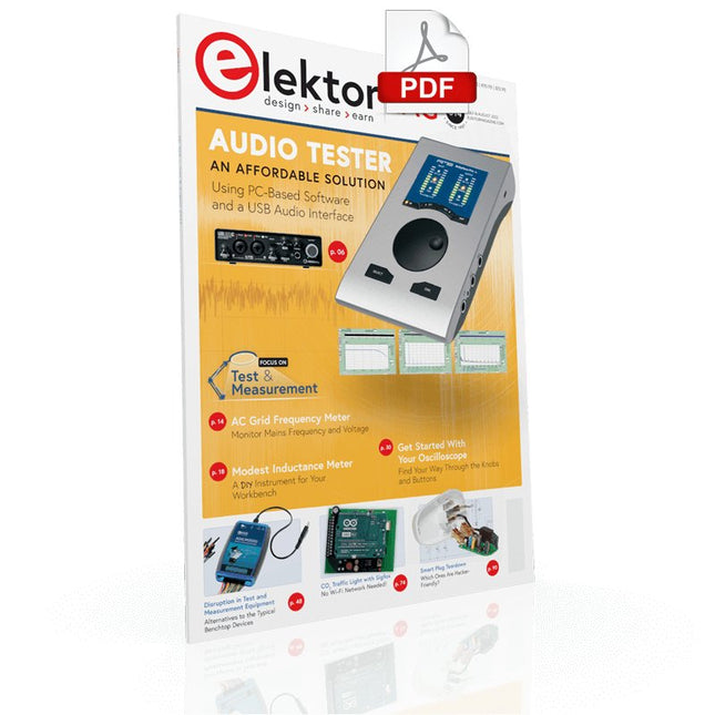
Measuring Does Not Have to be Expensive Low-Cost Audio TesterUsing PC-Based Software and a USB Audio Interface AC Grid Frequency MeterMonitor Mains Frequency and Voltage A Modest Inductance MeterAn Affordable Solution for Your Workbench Acoustic Wave HoveringA Look at the Makerfabs Acoustic Levitation Kit Starting Out in ElectronicsRectifiers E-FFWD: Looking Ahead Again! Get Started With Your OscilloscopeFind Your Way Through the Knobs and Buttons Raspberry Pi Pico Makes an MSF-SDRDecode a Time Signal with a Pi Pico SDR Moisture Sensors for Watering SystemsAutomatic Watering Disruption in Test and Measurement EquipmentInnovation from the Smaller Players Infographics 7-8/2022 Inspiration, That’s What It’s All AboutInterview with Entrepreneur Walter Arkesteijn, InnoFaith Beauty Sciences Minimizing EMC Interference from Storage Chokes GUIs with Python (Part 5)Tic-Tac-Toe Reed RelaysPeculiar Parts, the series Simple Analog ESR Meter With Moving-Coil Meter Precision Sigfox CO2 Traffic LightNo Wi-Fi Network Needed! Women in Tech“It's All About Merit Until Merit Has Tits” Low-Budget Tablet Oscilloscope ADS1013DGood Value for Money? Smart Plug TeardownWhich Ones Are Hacker-Friendly? Skin Impedance and Skin CapacitanceSmall Experiments From Life’s ExperienceNo Local Business Pokit Meter ReviewA Swiss army knife of test gear HexadokuThe Original Elektorized Sudoku
€ 7,50
-
Elektor Digital Elektor July/August 2023 (PDF)
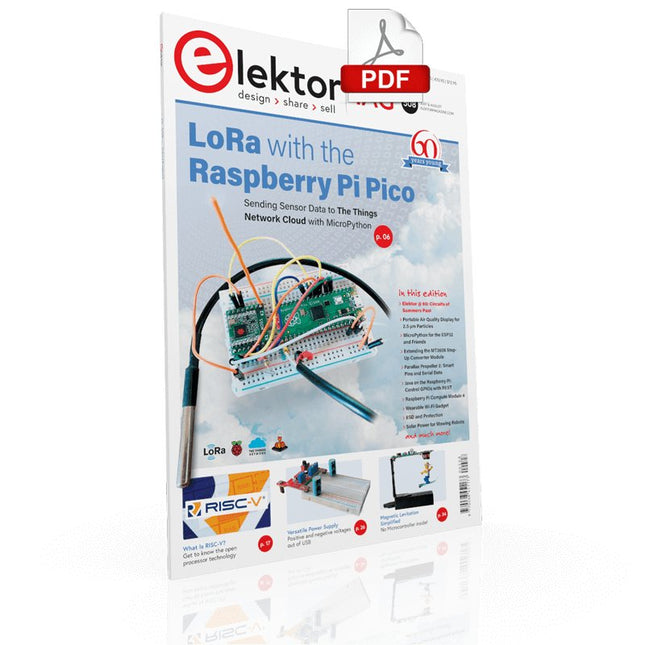
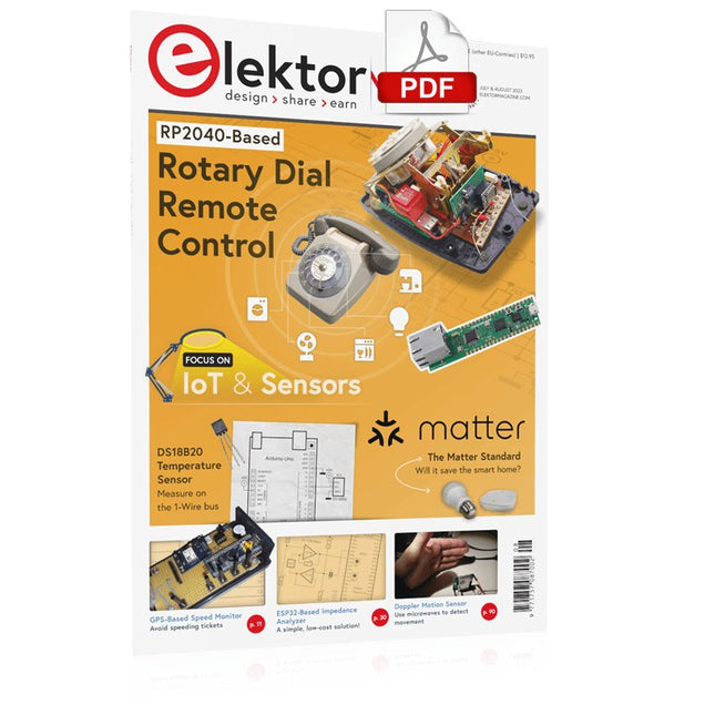
Elektor GREEN and GOLD members can download their digital edition here. Not a member yet? Click here. Rotary Dial Phone as Remote ControlTo Switch On the Lights, Dial 1; For the Coffee Maker, Dial 2 GPS-Based Speed MonitorNo More Speeding Tickets RGB Stroboscope with ArduinoA Colorful Adaptation of a Useful Instrument Wireless Emergency Push ButtonEnhanced Safety with LoRa Starting Out in ElectronicsFollow the Emitter Arbitrary, Independent Hysteresis Levels for Comparatorswith Simulations, Spreadsheets and Algebra ESP32-Based Impedance AnalyzerSimple, Low-Part-Count, and Inexpensive! HomeLab ToursEncouraging DIY The MCCAB Arduino Nano Training BoardAll-in-One Hardware for the “Microcontrollers Hands-On Course” From Life’s ExperienceModern Luddism Sensor 101: The DS18B20 Temperature SensorConnection to the 1-Wire Bus Is Matter the Thread to Save the Smart Home?New Standards to Simplify the Smart Home A Matter of CollaborationDeveloping with the Thing Plus Matter Board and Simplicity Studio Infographics: IoT and Sensors Matter, ExpressLink, Rainmaker — What Is This All About?Q&A with Amey Inamdar, Technical Marketing Director at Espressif Selecting Microcontroller Dev Kits for IoT and IIoT ApplicationsAn Introductory Guide Capacitors Do Not Always Behave Capacitively! An NTP Clock with CircuitPythonWhy Should You Use This Programming Language? Build a Cool IoT DisplayWith the Phambili Newt The HB100 Doppler Motion SensorTheory and Practice A Bare-Metal Programming Guide (Part 1)For STM32 and Other Controllers Siglent SDM3045X Multimeter Microprocessors for Embedded SystemsPeculiar Parts, the Series Microcontroller Documentation Explained (Part 3)Block Diagrams and More Low-Power LoRa Weather StationBuild a long-range weather station by yourself Transverter for the 70 cm Band Climate Calling EngineersMove Fast and Fix Things Hexadoku
€ 7,50
-

Elektor Digital Elektor July/August 2024 (PDF)
Elektor GREEN and GOLD members can download their digital edition here. Not a member yet? Click here. Small Thermal Imaging CameraAn Arduino UNO-Based DIY Solution Project Update #3: ESP32-Based Energy MeterIntegration and Testing with Home Assistant 2024: An AI OdysseyEnhancing Object Detection: Integrating Refined Techniques Raspberry Pi Goes AINew Kit Incorporates M.2 HAT+ With AI Accelerator Weather Station SensorsWhich One Should You Choose? AI-Based Water Meter Reading (1)Get Your Old Meter Onto the IoT! A GSM AlarmHarnessing GSM Technology for Remote Garage Safety Low-Power Thread Devices Optimized and ScrutinizedLow Power … Low Effort? From Life’s ExperienceThe Gender Gap DIY Cloud ChamberMaking Invisible Radiation Visible SparkFun Thing Plus MatterA Versatile Matter-Based IoT Development Board IoT RetrofittingMaking RS-232 Devices Fit for Industry 4.0 Enabling IoT with 8-Bit MCUs Technology Drives SustainabilityAdvances Lead to More Efficient Use of Energy in Many Applications AWS for Arduino and Co. (1)Using AWS IoT ExpressLink in Real Life Airflow Detector Using Arduino OnlyNo External Sensors Needed! Water Leak DetectorConnected to Arduino Cloud CrystalsPeculiar Parts, the Series Universal Garden LoggerA Step Towards AI Gardening Analog 1 kHz GeneratorSine Waves with Low Distortion Miletus: Using Web Apps OfflineSystem and Device Access Included! From 4G to 5GIs It Such an Easy Step? Starting Out in Electronics……Balances Out
€ 7,50
-

Elektor July/August 2025 (EN)
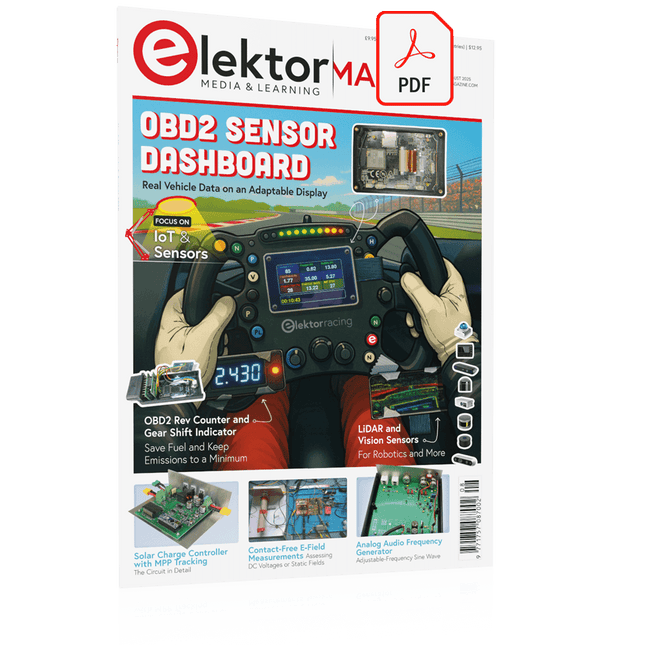
Elektor GREEN and GOLD members can download their digital edition here. Not a member yet? Click here. OBD2 Sensor DashboardOld Dials Sparked a Quest for Real Data OBD2: Add a Rev Counter and Gear Shift Indicator to Your CarRetro, but Super Useful LiDAR and Vision Sensors for Robotics Sensor+Test 2025 and PCIM 2025 Contact-Free E-Field Measurements (1)A Vibrating Membrane for Assessing DC Voltages or Static Electric Fields Wireless Mailbox NotifierFrom Optical Sensors to Radar, Exploring a Few Options Elektor Mini-WheelieA Self-Balancing Robot Solar CellsPeculiar Parts, the Series Getting Started With a Modern Radar SensorIs an Accurate Measurement on Your Radar? From Life’s ExperiencePaper Factory CybersecurityTough Times for Hackers Siglent Presents Next-Gen Multi-Channel OscilloscopesHigh-Performance Solutions for Modern Power and Embedded Systems Bluetooth 6.0 Brings Enhanced Distance-Ranging ApplicationsNew Version Offers Improved Device Positioning and Location Services Exploring Wireless Communication with BeagleY-AI Err-lectronicsCorrections, Updates, and Readers’ Letters Starting Out in Electronics……Concludes the Topic on Opamps A Powerful AI Code AssistantSpeed Up Your Development with Continue and Visual Studio Code Solar Charge Controller with MPPT (2)The Circuit Ultrasonic Obstacle DetectorA Simple Project to Help Those with Impaired Vision 2025: An AI OdysseyMid-Year Review Raspberry Pi Standalone MIDI Synthesizer (3)Making It Smarter and Adding a User Interface Meshtastic: A Demo ProjectAn Intelligent Mesh of LoRa Radios Analog Audio Frequency GeneratorHigh-Quality Adjustable Frequency Sine Wave Generator
€ 10,95
-
Elektor Digital Elektor July/August 2025 (PDF) EN
Elektor GREEN and GOLD members can download their digital edition here. Not a member yet? Click here. OBD2 Sensor DashboardOld Dials Sparked a Quest for Real Data OBD2: Add a Rev Counter and Gear Shift Indicator to Your CarRetro, but Super Useful LiDAR and Vision Sensors for Robotics Sensor+Test 2025 and PCIM 2025 Contact-Free E-Field Measurements (1)A Vibrating Membrane for Assessing DC Voltages or Static Electric Fields Wireless Mailbox NotifierFrom Optical Sensors to Radar, Exploring a Few Options Elektor Mini-WheelieA Self-Balancing Robot Solar CellsPeculiar Parts, the Series Getting Started With a Modern Radar SensorIs an Accurate Measurement on Your Radar? From Life’s ExperiencePaper Factory CybersecurityTough Times for Hackers Siglent Presents Next-Gen Multi-Channel OscilloscopesHigh-Performance Solutions for Modern Power and Embedded Systems Bluetooth 6.0 Brings Enhanced Distance-Ranging ApplicationsNew Version Offers Improved Device Positioning and Location Services Exploring Wireless Communication with BeagleY-AI Err-lectronicsCorrections, Updates, and Readers’ Letters Starting Out in Electronics……Concludes the Topic on Opamps A Powerful AI Code AssistantSpeed Up Your Development with Continue and Visual Studio Code Solar Charge Controller with MPPT (2)The Circuit Ultrasonic Obstacle DetectorA Simple Project to Help Those with Impaired Vision 2025: An AI OdysseyMid-Year Review Raspberry Pi Standalone MIDI Synthesizer (3)Making It Smarter and Adding a User Interface Meshtastic: A Demo ProjectAn Intelligent Mesh of LoRa Radios Analog Audio Frequency GeneratorHigh-Quality Adjustable Frequency Sine Wave Generator
€ 7,50
-
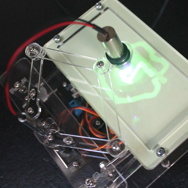
Elektor Labs Elektor Laser Head Upgrade for Sand Clock
The Elektor Laser Head transforms the Elektor Sand Clock into a clock that writes the time on glow-in-the-dark film instead of sand. In addition to displaying the time, it can also be used to create ephemeral drawings. The 5 mW laser pointer, with a wavelength of 405 nm, produces bright green drawings on the glow-in-the-dark film. For best results, use the kit in a dimly lit room. Warning: Never look directly into the laser beam! The kit includes all the necessary components, but soldering three wires is required. Note: This kit is also compatible with the original Arduino-based Sand Clock from 2017. For more details, see Elektor Magazine 1-2/2017 and Elektor Magazine 1-2/2018.
€ 34,95€ 24,95
Members identical
-
Elektor Digital Elektor March/April 2020 (PDF)
Elektor Magazine EN March/April 2020 (PDF)
€ 7,50
-

Elektor Digital Elektor March/April 2022 (PDF)
Build Your Own RISC-V ControllerFirst Steps with the NEORV32 RISC-V Softcore for Low-Cost FPGAs How to Use Arduino’s Serial PlotterPlotting Graphs With Arduino Is Easy CLUE from AdafruitA Smart Solution for IoT Projects Buffer Board for the Raspberry Pi 400Protect the I/Os Raspberry Pi RP2040 Boards Aplenty A Handbook on DIY Electronic Security and EspionageSRAM Heated or Deep-Frozen Component IdentificationTips & Tricks, Best Practices and Other Useful Information DIY Touchless Light Switch Starting out in ElectronicsMatching and Transforming What’s New in Embedded Development?Rust and Keeping IoT Deployments Updated Infographics How the Industrial and Automotive Sectors Will Benefit from 5G Moving Coil RelaysPeculiar Parts, the series HomeLab ToursEverything Revolves Around the Tools... Understanding the Neurons in Neural Networks (Part 4)Embedded Neurons Magnetic Levitation the Very Easy WayThe Third and Most Compact Version PLC Programming with the Raspberry Pi and the OpenPLC ProjectVisualization of PLC Programs with AdvancedHMI From Life's ExperiencePack Up and Leave Under Your RadarMicrocontrollers You Should Know About Monitor and Debug Over the AirA Solution for Arduino, ESP32 and Co. Portable Temperature- and Humidity-Measuring DeviceUsing Ready-Made Modules Lithium Battery Pack RepairSave Money + More Power! GUIs with PythonMeme-Generator Three Questions to Build OnWhy, What, and Who? HexadokuThe Original Elektorized Sudoku
€ 7,50
-
Elektor Digital Elektor March/April 2023 (PDF)
Elektor GREEN and GOLD members can download their digital edition here. Not a member yet? Click here. Cloc 2.0The Alarm Clock You've Always Wanted RP2040 PIO in PracticeExperiments Using the RP2040’s Programmable I/O Poor Man's ChipTweakerWe Have (Low-Budget) Ways of Making You Talk USB True Random Number GeneratorTwo PICs for the Price of One AVR Pimp My MicSelf-Designed Level Booster FFT with a MaixduinoFrequency spectrum display From Life’s ExperienceDesign Logic (or Non-Logic) UCN5804 Stepper Motor DriverPeculiar Parts, the Series Circuit Simulation With Micro-CapFirst Steps in a Complicated World PAUL Award 2022Young Technical Talents and Their Creative Solutions My First Software-Defined RadioBuilt in Less Than 15 Minutes Microcontroller Documentation Explained (Part 1)Datasheet structure What’s Next for AI and Embedded Systems?Tools, Platforms, and Writer Replacements Digitizing Vertical Farming Infographics: Embedded and AI Today and Tomorrow An Introduction to TinyML JetCarrier96A Versatile NVIDIA Jetson Development System Case Study: Taking EV Charging Global with a Universal RFID Solution High-Performance in Every ClassComputer-on-Module Standards Starting Out in ElectronicsLet’s Get Active! I²C Communication Using Node.js and a Raspberry PiSee Your Sensor Data in a Browser Video Output with Microcontrollers (2)VGA and DVI Output The Metronom Real-Time Operating SystemAn RTOS for AVR Processors DVI on the RP2040An Interview with Luke Wren, Chip Developer at Raspberry Pi Display HAT MiniShow the Weather Forecast on Raspberry Pi! WEEF 2022 Awards: Celebrate the Good Hexadoku
€ 7,50
-

Elektor Digital Elektor March/April 2024 (PDF)
Elektor GREEN and GOLD members can download their digital edition here. Not a member yet? Click here. CaptureCountAn Object Detector and Counter on the Raspberry Pi 5 Voltage Reference With Arduino Pro MiniLinearize and Calibrate Your Analog Inputs FPGAs for BeginnersThe Path From MCU to FPGA Programming Update: STM32 Wireless Innovation Design Contest 2024 Bluetooth LE With MAUIControl Apps for Android & Co. Port-Expanding Breakout BoardIncrease the Number of I/Os on Your Dev Board AI SpecialistMachine Learning with the Jetson Nano 2024: An AI OdysseyFirst Forays Into TensorFlow 262,144 Ways to Play The Game of LifeA Reader’s Project in Brief From Life’s ExperienceThe Chinese Dragon Get Your (Brushed DC) Motor Running!Sample Projects from the Elektor Motor Control Development Bundle ESP32-RS-232 AdapterA Wireless Link for Classic Test Equipment Starting Out in Electronics……More About Opamps ESP Library Recommendations Piezoelectric DevicesPeculiar Parts, the Series A Smart Object CounterImage Recognition Made Easy with Edge Impulse Resolve Your Trickiest Embedded Development Challenges ESP32 TerminalA Handheld Device with a Touch-Capable Display Getting Started With the Zephyr RTOSAs Powerful as It Is Hard to Master Award-Winning EthicsA Dialog with CTO Alexander Gerfer of Würth Elektronik eiSos on Enabling Innovation and Mindful Behavior Err-lectronicsCorrections, Updates, and Readers’ Letters Infographics: Embedded and AI Square Wave Generation BenchmarksExploring ESP32, Pico, and Other Microcontrollers
€ 7,50
-

Elektor March/April 2025 (EN)
Elektor GREEN and GOLD members can download their digital edition here. Not a member yet? Click here. The RISC-V Open-Source Processor Architecture16 Boards and MCUs You Should Know An FPGA-Based Audio Player with Equalizer (1)Mixing Digital Audio with an Arduino MKR Vidor 4000 Laser Head for Pico-Based Sand ClockDrawing with Light Enter the STM32 Edge AI Contest A Multi-Sensor Environmental Monitoring System for PlantsWireless Measurement of Water Supply and Light Conditions Maixduino AI-Powered Automatic DoormanFace Detection with a Camera Embedded Electronics 2024AI Is Set to Redefine the Industry Charge-Based In-Memory Compute at EnCharge AI AI Inferencing at 10 Times Lower Power and 20 Fold Lower Cost Click Board Helps Develop and Train ML Models for Vibration Analysis The Elektor Mini-WheelieA Self-Balancing Robot Kit MCU, I See YouMCUViewer Open-Source Multiplatform Debugging Tool USB 2.0 IsolatorElectrically Isolated Connections for USB Devices Intervention Before DamagePredictive Maintenance in Practice SPoE – Electromagnetic CompatibilitySingle-Pair with Power-Over-Ethernet Through the Eyes of EMC Color TV: A Wonder of Its TimeCreating a New World ECG Graph MonitoringAn Implementation with Hexabitz Modules and an STM32CubeMonitor The Battle for AI at the Edge HaLow Hits Record 16-km Wi-Fi Distance at 900 MHz First CHERI RISC-V Embedded Chip and Early Access Programme Third-Generation Wildfire Detection Uses Satellite Links From Life’s ExperienceChoice Overload Starting Out in Electronics……Continues Filtering and Controls Tone Quasi-Analog ClockworkA Remake of an Elektor Classic A Modular Approach to Sensor TestingThe ESP32-S3-Based Sensor Evaluation Board 2025: An AI OdysseyThe Rise of Foundation Models and Their Role in Democratizing AI Raspberry Pi Standalone MIDI Synthesizer (1)Preparing a Platform for Some Edge AI Experiments Err-lectronicsCorrections, Updates, and Readers’ Letters Universal AI RISC-V Processor Does It All — CPU, GPU, DSP, FPGA CEO Interview: Ventiva’s Thin and Cool Tech Dual-Core Programming with a Raspberry Pi PicoVenture Into the World of Parallel Programming
€ 10,95
-

Elektor Digital Elektor March/April 2025 (PDF) EN
Elektor GREEN and GOLD members can download their digital edition here. Not a member yet? Click here. The RISC-V Open-Source Processor Architecture16 Boards and MCUs You Should Know An FPGA-Based Audio Player with Equalizer (1)Mixing Digital Audio with an Arduino MKR Vidor 4000 Laser Head for Pico-Based Sand ClockDrawing with Light Enter the STM32 Edge AI Contest A Multi-Sensor Environmental Monitoring System for PlantsWireless Measurement of Water Supply and Light Conditions Maixduino AI-Powered Automatic DoormanFace Detection with a Camera Embedded Electronics 2024AI Is Set to Redefine the Industry Charge-Based In-Memory Compute at EnCharge AI AI Inferencing at 10 Times Lower Power and 20 Fold Lower Cost Click Board Helps Develop and Train ML Models for Vibration Analysis The Elektor Mini-WheelieA Self-Balancing Robot Kit MCU, I See YouMCUViewer Open-Source Multiplatform Debugging Tool USB 2.0 IsolatorElectrically Isolated Connections for USB Devices Intervention Before DamagePredictive Maintenance in Practice SPoE – Electromagnetic CompatibilitySingle-Pair with Power-Over-Ethernet Through the Eyes of EMC Color TV: A Wonder of Its TimeCreating a New World ECG Graph MonitoringAn Implementation with Hexabitz Modules and an STM32CubeMonitor The Battle for AI at the Edge HaLow Hits Record 16-km Wi-Fi Distance at 900 MHz First CHERI RISC-V Embedded Chip and Early Access Programme Third-Generation Wildfire Detection Uses Satellite Links From Life’s ExperienceChoice Overload Starting Out in Electronics……Continues Filtering and Controls Tone Quasi-Analog ClockworkA Remake of an Elektor Classic A Modular Approach to Sensor TestingThe ESP32-S3-Based Sensor Evaluation Board 2025: An AI OdysseyThe Rise of Foundation Models and Their Role in Democratizing AI Raspberry Pi Standalone MIDI Synthesizer (1)Preparing a Platform for Some Edge AI Experiments Err-lectronicsCorrections, Updates, and Readers’ Letters Universal AI RISC-V Processor Does It All — CPU, GPU, DSP, FPGA CEO Interview: Ventiva’s Thin and Cool Tech Dual-Core Programming with a Raspberry Pi PicoVenture Into the World of Parallel Programming
€ 7,50
-
Elektor Digital Elektor May/June 2020 (PDF)
Elektor Magazine EN May/June 2020 (PDF)
€ 7,50
-
Elektor Digital Elektor May/June 2021 (PDF)
Elektor Magazine EN May/June 2021 (PDF)
€ 7,50
-
Elektor Digital Elektor May/June 2022 (PDF)
Your First Steps with an ESP32-C3 and the IoTA Wi-Fi Button and Relay IoT Cloud a la Arduino Dual Geiger-Müller Tube Arduino ShieldA High Sensitivity, Very Low-Power Radiation Sensor CO2 GuardA DIY Approach to Monitoring Air Quality MonkMakes Air Quality Kit for Raspberry PiMeasures Temperature and eCO2 Starting Out in ElectronicsWelcome to the Diode Tips & Tricks for Testing ComponentsNo Expensive Equipment Required Reducing the Power Consumption of Your Mole RepellerAn ATtiny13 Replaces a 555 Light Switch DeLuxA Solution for High-Precision Light-Controlled Switching The Challenges in Bringing IoT Solutions to MarketWorries Around Security, Scalability, and Competition Infographics 5-6/2022 Preferably Wired After AllTips for Developing a 1 Gbit/s Interface in an Industrial Environment Bringing Real-Time Object Detection to MCUs with Edge Impulse FOMO Traveling-Wave TubesPeculiar Parts, the Series Narrowband Internet of ThingsStandards, Coverage, Agreements, and Modules Dragino LPS8 Indoor GatewaySpeedy LoRaWAN Gateway Setup Explore ATtiny Microcontrollers Using C and Assembly LanguageSample Chapter: ATtiny I/O Ports Err-lectronicsCorrections, Updates and Readers’ Letters LoRa GPS Tracker UpdateReceive and Show Location Using a Raspberry Pi Circuit Simulation with TINA Design Suite & TINACloudSample Chapter: Sinusoidal Oscillators From Life’s ExperienceAssembly Line Work The WinUI Graphics Framework for Windows AppsA Small Demo Application GUIs with PythonWorst GUI of the world Off-Grid Solar SystemsElectrical Energy Independent of the Mains Grid The 10-Year SmartphoneRenew Your Expectations HexadokuThe Original Elektorized Sudoku
€ 7,50
-
Elektor Digital Elektor May/June 2023 (PDF)
Elektor GREEN and GOLD members can download their digital edition here. Not a member yet? Click here. Knowledge for All! Super Servo TesterTest Up to Four Servos Stand-Alone or In-System Analog Signals and MicrocontrollersADCs, DACs, Current Measurement, and More embedded world 2023 Sub-Nyquist Sampling in PracticeReliably Capturing Higher Frequencies Using Subsampling Android Smartphone Here, ESP32 There?Practical Pproject Using the Android Wi-Fi API Active 1-kHz Filter for Distortion MeasurementBetter Measurements Through Optimization of the Measurement Signal Starting Out in Electronics......Multivibrating Cheerfully Further! Err-lectronicsCorrections, Updates and Readers’ Letters The New I3C ProtocolA Worthy Successor to I²C, or Just More Hot Air? BlueRC: IR Remote Control with Smartphone and ESP32Adaptive and Universal Microcontroller Documentation Explained (Part 2)Registers and Block Diagrams Automating Test and MeasurementProgramming Test Equipment to Do What You Want Infographics: Test and Measurement Overvoltage Protection for Safe OperationTransient Protection for Non-Isolated DC/DC Power Modules Wiha Measuring EquipmentReliable Electrical Testers and Meters Automating Testing and Collaborating on Test Results From Life’s ExperienceHigh-Level Electronics Energy LoggerMeasuring and Recording Power Consumption Assembling the 4tronix M.A.R.S. Rover Kit Parking Disk with E-Paper DisplayAn Innovative Digital Replacement eCO₂ Telegram botAir-Quality Measurement with Telegram Notification Behind the Scenes of DIY High-End AudioElektor’s Ton Giesberts Interviewed on the Fine Art of Analog Design HomeLab ToursWork in Progress... RFID Tag Reading and RFID Door LockSample Projects from the Elektor Arduino Experimenting Bundle Oscilloscope Current Probe for RFRF Current Measurements Made Easy Not for the Faint-Hearted: Robot Arm KitWith Raspberry Pi Pico and MicroPython Generative AIWho Made This Anyway? Hexadoku
€ 7,50
-

Elektor Digital Elektor May/June 2024 (PDF)
Elektor GREEN and GOLD members can download their digital edition here. Not a member yet? Click here. STM32 Wireless Innovation Design Contest Winners In-Circuit LC MeterA Prototype Study The AmpVolt Modular DC Power Meter (Part 1)Measure DC Power and Energy Consumption Up to 50 V and 5 A embedded world 2024 Repairing Electronic EquipmentTools, Techniques and Tips Starting Out in Electronics…...Continues the Opamp Theory A Simple DDS Signal GeneratorDirect Digital Synthesis in Its Purest Form Sparkplug at a GlanceA Specification for MQTT Data The CRTCPeculiar Parts, the Series Radar-Controlled LightingAutomatic Stairway Light With Human Presence Detection Digital Bubble Level and Active Stroboscopic Disc for TurntablesFine-Tune Your Record Player With This All-In-One Tool Open Source and Its Significance for the Electronics Industry (2) M12 Circular Connector With A-codingFirst Choice for Industrial Applications The Arduino-Inside Measurement LabAn 8-in-1 Test & Measurement Instrument for the Electronics Workbench Sound Card Performs Gain/Phase and Impedance AnalysisFor Frequencies From 100 Hz to 90 kHz Measuring pH Value With the Arduino UNO R4Check the Quality of Your Water From Life’s ExperiencePangpong Butt Launcher FNIRSI 1014D Digital Storage OscilloscopeGood Performance for Tight Budgets 2024: An AI OdysseyGetting Object Detection Up and Running 10 MHz Reference GeneratorHighly Accurate, With Distributor and Galvanic Isolation Project Update #2: ESP32-Based Energy MeterSome Enhancements Err-lectronicsCorrections, Updates, and Readers’ Letters An Interview with Eben Upton, CEO of Raspberry PiRaspberry Pi 5 and Beyond
€ 7,50
-
Elektor May/June 2025 (EN)
Elektor GREEN and GOLD members can download their digital edition here. Not a member yet? Click here. PbMonitor v1.0A Battery-Monitoring System for UPS and Energy Storage Applications Solar Charge Controller with MPPT (1)Basic Principles of a Solar Controller for Stand-Alone Systems B-Field Integration Magnetometer With Home-Made Sensors Precise or Accurate?Your Instruments Need to Be Both! AD7124 A Precision ADC in PracticeFeatures for Sensor Signal Conditioning PID Control ToolOptimize Your Parameters Easily embedded world 2025 Starting Out in Electronics……Continues with Tone Control Academy Pro BoxBook + Online Course + Hardware Milliohmmeter AdapterUses the Precision of Your Multimeter The Next Leap in SemiconductorsOnward Toward 1.4 nm Through-Hole Technology ConnectorsThe Best of Two Worlds: THR Frequency CounterPortable and Auto-Calibrating Via GPS Analog MetersPeculiar Parts, the Series Stand-Alone Crystal TesterHow Accurate Is Your Clock Source? Low-Cost I²C TesterConnect I²C Devices Directly to Your PC From Life’s ExperienceWho Doesn’t Honor the Small Things? 2025: An AI OdysseyThe Transformative Impact on Software Development Err-lectronicsCorrections, Updates, and Readers’ Letters Raspberry Pi Standalone MIDI Synthesizer (2)Enhancing Our Setup with Intelligence Nortonized Wien Bridge OscillatorSmall Changes Yield Significant Improvements Putting a $0.10 Controller to the TestThe CH32V003 RISC-V Microcontroller and MounRiver Studio in Practice An FPGA-Based Audio Player with Equalizer (2)Adding Volume Control, Advanced Mixing, and a Web Interface
€ 10,95
-

Elektor Digital Elektor May/June 2025 (PDF) EN
Elektor GREEN and GOLD members can download their digital edition here. Not a member yet? Click here. PbMonitor v1.0A Battery-Monitoring System for UPS and Energy Storage Applications Solar Charge Controller with MPPT (1)Basic Principles of a Solar Controller for Stand-Alone Systems B-Field Integration Magnetometer With Home-Made Sensors Precise or Accurate?Your Instruments Need to Be Both! AD7124 A Precision ADC in PracticeFeatures for Sensor Signal Conditioning PID Control ToolOptimize Your Parameters Easily embedded world 2025 Starting Out in Electronics……Continues with Tone Control Academy Pro BoxBook + Online Course + Hardware Milliohmmeter AdapterUses the Precision of Your Multimeter The Next Leap in SemiconductorsOnward Toward 1.4 nm Through-Hole Technology ConnectorsThe Best of Two Worlds: THR Frequency CounterPortable and Auto-Calibrating Via GPS Analog MetersPeculiar Parts, the Series Stand-Alone Crystal TesterHow Accurate Is Your Clock Source? Low-Cost I²C TesterConnect I²C Devices Directly to Your PC From Life’s ExperienceWho Doesn’t Honor the Small Things? 2025: An AI OdysseyThe Transformative Impact on Software Development Err-lectronicsCorrections, Updates, and Readers’ Letters Raspberry Pi Standalone MIDI Synthesizer (2)Enhancing Our Setup with Intelligence Nortonized Wien Bridge OscillatorSmall Changes Yield Significant Improvements Putting a $0.10 Controller to the TestThe CH32V003 RISC-V Microcontroller and MounRiver Studio in Practice An FPGA-Based Audio Player with Equalizer (2)Adding Volume Control, Advanced Mixing, and a Web Interface
€ 7,50
-
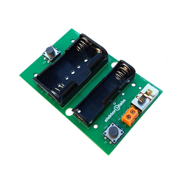
Elektor Labs Elektor Milliohmmeter Adapter
The Elektor Milliohmmeter Adapter uses the precision of a multimeter to measure very low resistance values. It is an adapter that converts a resistance into a voltage that can be measured with a standard multimeter. The Elektor Milliohmmeter Adapter can measure resistances below 1 mΩ using a 4-wire (Kelvin) method. It is useful for locating short circuits on printed circuit boards (PCB). The adapter features three measurement ranges – 1 mΩ, 10 mΩ, and 100 mΩ – selectable via a slide switch. It also includes onboard calibration resistors. The Elektor Milliohmmeter Adapter is powered by three 1.5 V AA batteries (not included). Specifications Measurement ranges 1 mΩ, 10 mΩ, 100 mΩ, 0.1% Power supply 3x 1.5 V AA batteries (not included) Dimensions 103 x 66 x 18 mm (compatible with Hammond 1593N-type enclosure, not included) Special feature On-board calibration resistors Downloads Documentation
€ 34,95
Members € 31,46
-
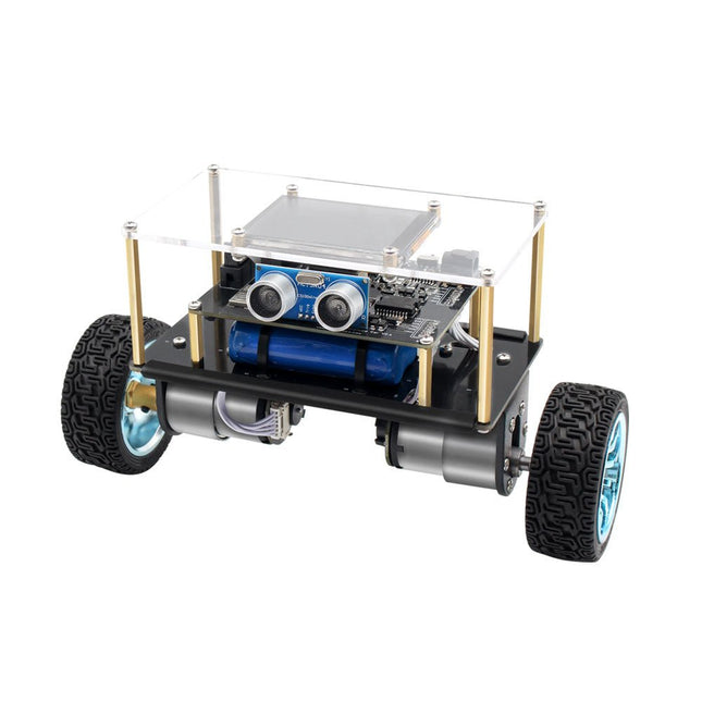
Elektor Labs Elektor Mini-Wheelie Self-Balancing Robot
Arduino-compatible, ESP32-controlled, 2-wheeled Balancing Robot The Elektor Mini-Wheelie is an experimental autonomous self-balancing robot platform. Based on an ESP32-S3 microcontroller, the self-balancing robot is fully programmable using the Arduino environment and open-source libraries. Its wireless capabilities allow it to be controlled remotely over Wi-Fi, Bluetooth or ESP-NOW or to communicate with a user or even another robot. An ultrasonic transducer is available for detecting obstacles. Its color display can be used for displaying cute facial expressions or, for the more down-to-earth users, cryptic debug messages. The robot comes as a neat kit of parts that you must assemble yourself. Everything is included, even a screwdriver. Note: The Mini-Wheelie is an educational development platform intended for learning, experimentation, and robotics development. It is not classified as a toy for children, and its features, documentation, and intended audience reflect this purpose. The product is aimed at students, educators, and developers who wish to explore robotics, programming, and hardware integration in an educational setting. Specifications ESP32-S3 microcontroller with Wi-Fi and Bluetooth MPU6050 6-axis Inertial Measurement Unit (IMU) Two independently controlled 12 V electric motors with tachometer Ultrasonic transducer 2.9" TFT color display (320 x 240) MicroSD card slot Battery power monitor 3S rechargeable Li-Po battery (11.1 V/2200 mAh) Battery charger included Arduino-based open-source software Dimensions (W x L x H): 23 x 8 x 13 cm Included 1x ESP32-S3 Mainboard + MPU6050 module 1x LCD board (2.9 inch) 1x Ultrasonic sensor 1x Battery pack (2200 mAh) 1x Battery charger 1x Motor tyre kit 1x Case board 1x Acrylic board 1x Screwdriver 1x Protective strip 1x Flex cable B (8 cm) 1x Flex cable A (12 cm) 1x Flex cable C 4x Copper column A (25 mm) 4x Copper column B (55 mm) 4x Copper column C (5 mm) 2x Plastic nylon column 8x Screws A (10 mm) 24x Screws B (M3x5) 8x Nuts 24x Metal washers 2x Zip tie 1x MicroSD card (32 GB) Downloads Documentation
€ 99,95€ 84,95
Members identical
-
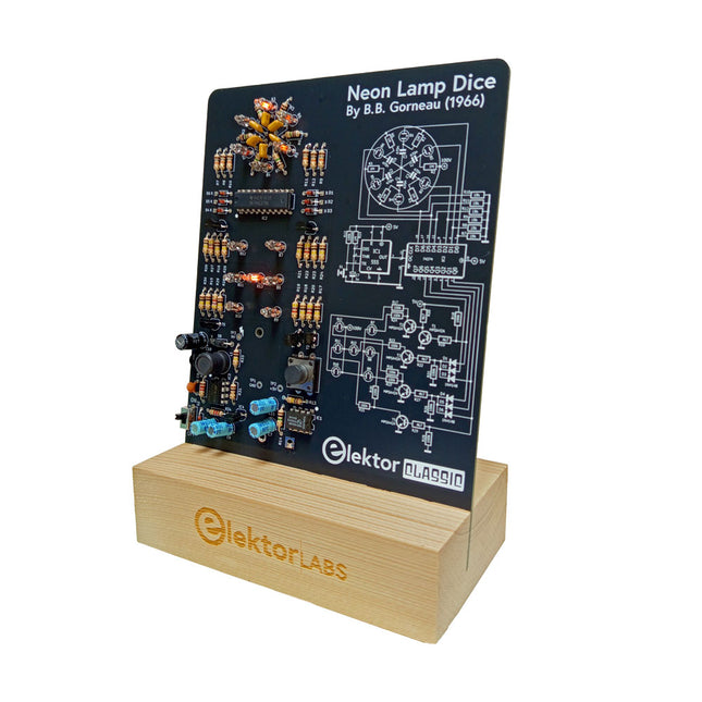
Elektor Labs Elektor Neon Lamp Dice
A Retro Roll with a Neon Soul LED-based dice are common, but their light is cold. Not so for this electronic neon dice, which displays its value with the warm glow of neon lamps. It is perfect for playing games on cold, dark winter evenings. The pips of the dice are neon lamps and the random number generator has six neon lamps to show that it is working. Even though the dice has an on-board 100-V power supply, it is completely safe. As with all Elektor Classic products, the dice too has its circuit diagram printed on the front while an explanation of how the circuit works can be found on the rear side. The Neon Lamp Dice comes as a kit of easy-to-solder through-hole parts. The power supply is a 9-V battery (not included). Features Warm Vintage Glow Elektor Heritage Circuit Symbols Tried & Tested by Elektor Labs Educational & Geeky Project Through-Hole Parts Only Included Printed Circuit Board All Components Wooden Stand Required 9 V battery Component List Resistors (THT, 150 V, 0.25 W) R1, R2, R3, R4, R5, R6, R14 = 1 MΩ R7, R8, R9, R10, R11, R12 = 18 kΩ R13, R15, R16, R17, R18, R21, R23, R24, R25, R26, R28, R30, R33 = 100 kΩ R32, R34 = 1.2 kΩ R19, R20, R22, R27, R29 = 4.7 kΩ R31 = 1 Ω Capacitors C1, C2, C3, C4, C5, C6 = 470 nF, 50 V, 5 mm pitch C7, C9, C11, C12 = 1 µF, 16 V, 2 mm pitch C8 = 470 pF, 50 V, 5 mm pitch C10 = 1 µF, 250 V, 2.5 mm pitch Inductors L1 = 470 µH Semiconductors D1, D2, D3, D4, D5, D6, D7 = 1N4148 D8 = STPS1150 IC1 = NE555 IC2 = 74HC374 IC3 = MC34063 IC4 = 78L05 T1, T2, T3, T4, T5 = MPSA42 T6 = STQ2LN60K3-AP Miscellaneous K1 = PP3 9 V battery holder NE1, NE2, NE3, NE4, NE5, NE6, NE7, NE8, NE9, NE10, NE11, NE12, NE13 = neon light S2 = Miniature slide switch S1 = Pushbutton (12 x 12 mm)
€ 39,95€ 15,98
Members identical
-
Elektor Digital Elektor November/December 2020 (PDF)
Elektor Magazine EN November/December 2020 (PDF)
€ 7,50


