Products
-
Elektor Digital Elektor AI Guest Edition 2024 (PDF) EN
Elektor GREEN and GOLD members can download their digital edition here. Not a member yet? Click here. The AlertAlfred AI Security SystemPowered by a Raspberry Pi 5 and the Hailo 8L Module AI in Electronics DevelopmentAn Update After Only One Year Intro to AI AlgorithmsPrompt: Which Algorithms Implement Each AI Tool? Single-Board Computers for Artificial Intelligence ProjectsBackground and Overview From Sensor Data to Machine Learning ModelsGesture Detection with an Accelerometer and Edge Impulse Build a Leaky Integrate-and-Fire Spiking NeuronArtificial Intelligence Without Software ChatGPT for Electronic DesignDoes GPT-4o Do It Any Better? Bringing AI to the Edge with ESP32-P4 Exploring Speech Functions on Raspberry Pi ZeroWhen Overclocking Gives Freedom of Speech The Growing Role of Edge AIA Trend Shaping the Future Unlocking the Power of Edge AIA Conversation with François de Rochebouët of STMicroelectronics A VHDL Clock Made with ChatGPT AI’s Real ImpactSayash Kapoor on “AI Snake Oil” and More The Latest Stuff From BeagleBoardBeagleY-AI, BeagleV-Fire, BeagleMod, BeaglePlay and BeagleConnect Freedom Mosquito Detection Using Open Datasets and Arduino Nicla Vision AI Today and Tomorrow: Insights from Espressif, Arduino, and SparkFun Artificial Intelligence Timeline BeagleY-AIThe Latest SBC for AI Applications AI in FocusPerspectives from the Elektor Community Machine Vision with OpenMVCreate a Soda Can Detector A Conversation with the Digital MindChatGPT vs Gemini Skilling Me Softly with This Bot?Is the AI Revolution in the Electronic Field Failing Due to a Lack of Social Precision?
€ 7,50
-

Elektor Labs Elektor AM Transmitter Kit
Build Your Own Vintage Radio Broadcaster The Elektor AM Transmitter Kit allows streaming audio to vintage AM radio receivers. Based on a Raspberry Pi Pico microcontroller module, the AM Transmitter can transmit on 32 frequencies in the AM band, from 500 kHz up to 1.6 MHz in 32 steps of approx. 35 kHz. The frequency is selected with a potentiometer and shown on a 0.96" OLED display. A pushbutton allows toggles the transmitting mode between On and Off. The range of the transmitter depends on the antenna. The onboard antenna provides a range of a few centimeters, requiring the AM Transmitter to be placed close to or inside the radio. An external loop antenna (not included) can be connected to increase the range. The Elektor AM Transmitter Kit comes as a kit of parts that you must solder to the board yourself. Features The board is compatible with a Hammond 1593N enclosure (not included).A 5 VDC power supply with micro-USB connector (e.g., an old phone charger) is needed to power the kit (not included). Current consumption is 100 mA. The Arduino software (requiring Earle Philhower’s RP2040 Boards Package) for the Elektor AM Transmitter Kit plus more information is available at the Elektor Labs page of this project. Component List Resistors R1, R4 = 100 Ω R2, R3, R8 = 10 kΩ R5, R6, R9, R10, R11 = 1 kΩ R7 = optional (not included) P1 = potentiometer 100 kΩ, linear Capacitors C1 = 22 µF 16V C2, C4 = 10 nF C3 = 150 pF Miscellaneous K1 = 4×1 pin socket K2, K3 = 3.5 mm socket Raspberry Pi Pico pushbutton, angle mount 0.96" monochrome I²C OLED display PCB 150292-1
€ 34,95€ 29,95
Members identical
-

Elektor Classics Elektor Archive 1974-2025 (USB Stick) EN
NEW: Now incl. volume 2025 + Elektor GPT 5 Elektor Decades (’70s, ’80s, ’90s, ’00s, and ’10s) on a USB Stick This USB stick (32 GB, USB 3.0) is loaded with all the Elektor magazine English editions (as PDFs) from 1974 to 2025. Elektor engineers, authors, and editors aim to inspire you to master electronics and computer technology by presenting professionally designed circuits that are easy to build. We also cover the latest developments in electronics and information technology. With the Elektor Archive on a USB stick, you can browse our previous English editions at your convenience and learn about MCU-based projects, robotics, electronics testing, embedded programming, analog techniques, and much more. All the Elektor magazine editions are stored as PDFs on a 32-GB USB stick (USB 3.0). The 10,000+ articles have been classified by date of publication (month/year), and a comprehensive index enables you to search the entire USB stick. Subject areas include: Audio & video Computers & microcontrollers Radio, hobby & modelling Home & garden Power supplies & batteries Test & measurement Software And everything else that doesn’t fit in one of these categories. NEW Elektor GPT is an AI-powered tool that helps users navigate through the decades-long Elektor archive. Using advanced search algorithms and natural language processing, Elektor GPT quickly finds articles, projects, and other resources from the archive. Specifications Storage 32 GB Interfaces 1x USB-A1x USB-C System requirements PC with Adobe Reader 7.0 or higher Web browser
€ 199,95€ 99,95
-
Elektor Digital Elektor Arduino Guest Edition 2022 (PDF) EN
Elektor GREEN and GOLD members can download their digital edition here. Not a member yet? Click here. Arduino Portenta Machine Control and Arduino Portenta H7A CAN-to-MQTT Gateway Demo Project Unboxing the Elektor LCR Meter with David Cuartielles MicroPython Enters the World of Arduino Connected Projects, SimplifiedDive Into the Arduino Cloud Introduction to TinyMLBig Is Not Always Better Arduino K-Way Writing Arduino Sketches Just Got Better Get to Know Arduino Getting Started with the Portenta X8Manage Software Securely with Containers Build, Deploy, and Maintain Scalable, Secure ApplicationsWith Arduino Portenta X8 Featuring NXP’s i.MX 8M Mini Applications Processor and EdgeLock SE050 Secure Element How I Automated My HomeArduino CEO Fabio Violante Shares Solutions Altair 8800 SimulatorHardware Simulation of a Vintage Computer MS-DOS on the Portenta H7Run Old-School Software on Contemporary Hardware Grow It YourselfA Digitally Controlled, Single-Box Solution for Indoor Farming Save the Planet With Home Automation?MQTT on the Arduino Nano RP2040 Connect Go Professional with Arduino Pro Smart Ovens Take a Leap Into the Future Tagvance Builds Safer Construction Sites with Arduino Santagostino Breathes Easywith Remote Monitoring that Leverages AI for Predictive Maintenance Security Flies High with RIoT Secure’s MKR-Based Solution Open-Source Brings a New Generation of Water Management to the World SensoDetect Deforestation with Sound Analysis The Mozzi Arduino Library for Sound SynthesisInsights from Tim Barrass The New Portenta X8 (with Linux!) and Max Carrier Redefine What’s Possible How Using Arduino Helps Students Build Future Skills Must-Haves for Your Electronics Workspace The Importance of Robotics in Education Dependable IoT Based Upon LoRa Unboxing the Portenta Machine Control 8-Bit Gaming with Arduboy Reducing Water Usage at Horseback Riding TracksAn IoT to Constantly Monitor Soil Humidity and Temperature Levels The Panettone ProjectA sourdough starter management and maintenance system Supporting Arduino Resellers Space Invaders with Arduino Art with ArduinoInspiring Insights from Artists and Designers Arduino Product Catalogue The Future of Arduino
€ 7,50
-

Elektor Labs Elektor Arduino MultiCalculator
The Elektor MultiCalculator Kit is an Arduino-based multifunction calculator that goes beyond basic calculations. It offers 22 functions including light and temperature measurement, differential temperature analysis, and NEC IR remote control decoding. The Elektor MultiCalculator is a handy tool for use in your projects or for educational purposes. The kit features a Pro Mini module as the computing unit. The PCB is easy to assemble using through-hole components. The enclosure consists of 11 acrylic panels and mounting materials for easy assembly. Additionally, the device is equipped with a 16x2 alphanumeric LCD, 20 buttons, and temperature sensors. The Elektor MultiCalculator is programmable with the Arduino IDE through a 6-way PCB header. The available software is bilingual (English and Dutch). The calculator can be programmed with a programming adapter, and it is powered through USB-C. Modes of Operation Calculator 4-Ring Resistor Code 5-Ring Resistor Code Decimal to Hexadecimal and Character (ASCII) conversion Hexadecimal to Decimal and Character (ASCII) conversion Decimal to Binary and Character (ASCII) conversion Binary to Decimal and Hexadecimal conversion Hz, nF, capacitive reactance (XC) calculation Hz, µH, inductive reactance (XL) calculation Resistance calculation of two resistors connected in parallel Resistance calculation of two resistors connected in series Calculation of unknown parallel resistor Temperature measurement Differential temperature measurement T1&T2 and Delta (δ) Light measurement Stopwatch with lap time function Item counter NEC IR remote control decoding AWG conversion (American Wire Gauge) Rolling Dice Personalize startup message Temperature calibration Specifications Menu languages: English, Dutch Dimensions: 92 x 138 x 40 mm Build time: approx. 5 hours Included PCB and though-hole components Precut acrylic sheets with all mechanical parts Pro Mini microcontroller module (ATmega328/5 V/16 MHz) Programming adapter Waterproof temperature sensors USB-C cable Downloads Software
€ 49,95€ 39,95
Members identical
-

Elektor Labs Elektor Arduino Nano MCCAB Training Board
The Elektor Arduino Nano MCCAB Training Board contains all the components (incl. Arduino Nano) required for the exercises in the "Microcontrollers Hands-on Course for Arduino Starters", such as light-emitting diodes, switches, pushbuttons, acoustic signal transmitters, etc. External sensors, motors or assemblies can also be queried or controlled with this microcontroller training system. Specifications (Arduino Nano MCCAB Training Board) Power Supply Via the USB connection of the connected PC or an external power supply unit (not included) Operating Voltage +5 Vcc Input Voltage All inputs 0 V to +5 V VX1 and VX2 +8 V to +12 V (only when using an external power supply) Hardware periphery LCD 2x16 characters Potentiometer P1 & P2 JP3: selection of operating voltage of P1 & P2 Distributor SV4: Distributor for the operating voltagesSV5, SV6: Distributor for the inputs/outputs of the microcontroller Switches and buttons RESET button on the Arduino Nano module 6x pushbutton switches K1 ... K6 6x slide switches S1 ... S6 JP2: Connection of the switches with the inputs of the microcontroller Buzzer Piezo buzzer Buzzer1 with jumper on JP6 Indicator lights 11 x LED: Status indicator for the inputs/outputs LED L on the Arduino Nano module, connected to GPIO D13 JP6: Connection of LEDs LD10 ... LD20 with GPIOs D2 ... D12 Serial interfacesSPI & I²C JP4: Selection of the signal at pin X of the SPI connector SV12 SV9 to SV12: SPI interface (3.3 V/5 V) or I²C interface Switching output for external devices SV1, SV7: Switching output (maximum +24 V/160 mA, externally supplied) SV2: 2x13 pins for connection of external modules 3x3 LED matrix(9 red LEDs) SV3: Columns of the 3x3 LED matrix (outputs D6 ... D8) JP1: Connection of the rows with the GPIOs D3 ... D5 Software Library MCCABLib Control of hardware components (switches, buttons, LEDs, 3x3 LED matrix, buzzer) on the MCCAB Training Board Operating Temperature Up to +40 °C Dimensions 100 x 100 x 20 mm Specifications (Arduino Nano) Microcontroller ATmega328P Architecture AVR Operating Voltage 5 V Flash Memory 32 KB, of which 2 KB used by bootloader SRAM 2 KB Clock Speed 16 MHz Analog IN Pins 8 EEPROM 1 KB DC Current per I/O Pins 40 mA on one I/O pin, total maximum 200 mA on all pins together Input Voltage 7-12 V Digital I/O Pins 22 (6 of which are PWM) PWM Output 6 Power Consumption 19 mA Dimensions 18 x 45 mm Weight 7 g Included 1x Elektor Arduino Nano Training Board MCCAB 1x Arduino Nano
€ 79,95
Members € 71,96
-
Elektor Classics Elektor Audio Collection (USB Stick)
Some Highlights from the contents Surround-sound decoder Compact amp Sampling rate converter Battery powered preamplifier Titan 2000 amplifier Crescendo Millennium amplifier Audio-DAC/ADC IR-S/PDFI receiver and transmitter High-End Power Amp Hi-fi Wireless Headset Paraphase Tone Control and more… Using Adobe Reader you are able to browse and search the articles on your computer, as well as print texts, circuit diagrams and PCB layouts.
€ 69,95€ 27,98
Members identical
-
Elektor Digital Elektor Circuit Special 2023 PDF (EN)
Elektor GREEN and GOLD members can download their digital edition here. Not a member yet? Click here. Tiny Solar SupplySunlight In, 3.3 V Out Solid-State Stereo Audio SwitchFree of Clicks and Moving Parts Large RGB DigitWith Through-Hole WS2812 LEDs Microphone Preamplifier with 48-V Phantom Power DistributionGreat for Podcasting and Pro Audio Square Wave Generators with Duty Cycle and Frequency ControlsSimple Circuits with CMOS and TTL ICs Simple Dynamic CompressorWith Soft Control and Warm Sound Simple Electronic Lock Active RectifierA solution or 2…40 V at up to 3 A with Reverse Current Suppression On / Off Switching System for Active Boxes Unbalanced/Balanced ConverterWith RFI Filter and DC Protection 2023: An AI OdysseyWhere Did It Come From? Where Is It Going? Speed Controller for Fan or VentilatorWith Manual and Thermostat Modes The Latest from Arduino Project HubNew Projects from the Community Power Overload MonitorMonitor Power Lines for Excessive Current Blink in the Dark Without TransistorsAn Oscillator with Only Two-Terminal Parts Morse Code GeneratorUse It as Beacon or Learning Device! Programmable Video DACHandles Any Format up to RGB888 A T(eeny) Tiny PianoWithout Moving Parts Dual Dice without MCUDual Dice on a Single PCB – Plus Some Design Tricks Electronic Scarecrow Circuits to Amuse, Inspire, and Amaze LC-LP-HA ThermometerAccurate Measurements and a Binary Display THD GeneratorGenerating Distortion on Purpose Thyristor-Based Overtemperature IndicatorElectronic Components Used Unconventionally PTC Fuse Flip-Flop Funny BirdA Chirping Elektor Classic Neon Lamp with a Microcontroller Temperature-Stabilized IC Current SourceNeutralizing the Temperature Drift of Integrated Current Sources Second-Order Adjustable Treble BoostA Special Hearing Aid for the Elderly Edwin Comes HomeA Look Back After 53 Years One-Armed BanditA Simple, Fun, Nostalgic, and Educational Elektor Classic! Simple Digitally Controlled Variable Resistor Water Leak ProtectionSafeguard and Alarm for Water Leaks Eco-Timer with Auto-ShutdownNeeds 0.0 mW in Off Mode! ChatGPT and Arduino ZD MeterMeasuring Z Voltages of Z Diodes ≤ 100 V Servo Tester ESP32 Windows Controller with Free Software Analog and Mixed-Signal ICs by MicrochipLow-Consumption Power Management and Signal Processing Interface StandardsFilter and Surge Protection for the I²C Bus Li-Ion Battery MonitorResidual Charge Indicator Provides Visual Feedback PS/2 Mouse As Rotary Encoder (and More…) Simple Twilight Switchfor Retrofitting Lamps or Installations Water Pump ControllerPrepare Yourself Against Rising Water Levels Solar-Powered Christmas FM Radio BallAll You Want for Christmas Is This Vibration Sensor with RelayTap or Shake to Switch On Continuity TesterSensitive and Unintrusive Power On/Off with a Pushbutton Mini-Drill Power Control 2023A Revision of a Design from 1980 Digital Vibration SensorTurn Vibrations into Precisely Timed Pulses Reverse-Polarity Protection with Low Voltage Drop A Low-Cost Frequency Standard Tiny DCF77 SimulatorAn Accurate Fake-Time Standard The Lilygo T-PicoC3Combines RP2040 and ESP32-C3 with Full Color-TFT Display
€ 7,50
-
Elektor Digital Elektor Circuit Special 2023 PDF (NL)
Elektor GREEN en GOLD leden kunnen deze uitgave hier downloaden.Nog geen lid? Klik hier om een lidmaatschap af te sluiten. Mini-zonnevoedingzon in, 3,3 V uit Solid-state stereo-audioschakelaarklikvrij en zonder bewegende onderdelen Grote RGB-digitmet through-hole WS2812 LED’s Microfoon-voorversterker met 48V-fantoomvoedingvoor podcasting en pro-audio Blokgolfgeneratoren met regelbare duty cycle en frequentiesimpele schakelingen met CMOS- en TTL-IC’s Eenvoudige dynamiekcompressorsofte aansturing, warm geluid Simpel elektronisch slot Actieve gelijkrichtervoor 2...40 V bij maximaal 3 A met tegenstroomonderdrukking Actieve boxen in- en uitschakelen Ongebalanceerd/gebalanceerd-convertermet RF-filter en DC-bescherming 2023: een AI-odysseewaar komt het vandaan en waar gaat het naar toe? Snelheidsregelaar voor ventilatormet handmatige en thermostaatmodus Laatste nieuwtjes van Arduino Project Hubnieuwe projecten uit de community Overbelastingsmonitorbewaakt netsnoeren Transistorloos knipperlicht in het donkeroscillator met alleen tweedraads onderdelen Morsecode-generatorvoor gebruik als baken of leermiddel! Programmeerbare video-DACvoor elk formaat tot RGB888 Kleintje klavierzonder bewegende onderdelen Dubbel-dobbel zonder microprocessordubbele dobbelsteen op een enkele print – plus enkele ontwerptrucs Elektronische vogelverschrikker Amusante, inspirerende en verbazingwekkende schakelingen LC/LP/HA-thermometernauwkeurige metingen en een binair display THD-generatorvervorming, maar dan opzettelijk Overtemperatuur-indicator met thyristorelektronische onderdelen ongebruikelijk gebruikt Een PTC-flipflop Sociale vogeleen tsjilpende Elektor Klassieker Neonlamp plus microcontroller Temperatuurgestabiliseerde IC-stroombronneutraliseer de temperatuurdrift van deze driebeners Regelbare tweede-orde hogetonen-boostergehoorsteuntje voor ouderen Edwin komt naar huisherinneringen na 53 jaar Eénarmige bandieteen eenvoudige, leuke, nostalgische en leerzame Elektor-klassieker! Eenvoudige digitaal gestuurde variabele weerstand Lekdetectorbeveiligt en alarmeert bij lekkages Eco-timer met automatische uitschakelingverbruikt niets in uitgeschakelde toestand! ChatGPT en Arduino Zenermetermeet de Z-spanning van Z-diodes ≤ 100 V Servotester ESP32 Windows-controller met gratis software Analoge en mixed-signal IC’s van Microchipzuinige signaalverwerking Interfacenormenfilter en overspanningsbeveiliging voor de I²C-bus Li-Ion accumonitorrestlading-indicator geeft visuele feedback PS/2-muis als draai-encoder (en meer...) Simpele schemerschakelaarvoor bestaande lampen of installaties Controller voor waterpompbereid je voor op hoogwater Kerstbal met FM-zonneradiomeer heb je voor de kerst niet nodig Trillingssensor met relaistik of schud om in te schakelen Doorgangstestergevoelig en niet storend In- en uitschakelen met een drukknop Regeling voor mini-boor (2023)een ontwerp uit 1980 herzien Digitale trillingssensorzet trillingen om in nauwkeurig getimede pulsen Ompoolbeveiliging met kleine spanningsval Goedkope frequentiestandaard Kleine DCF77-simulatornauwkeurige fake-tijdstandaard De Lilygo T-PicoC3combineert RP2040 en ESP32-C3 met een full-color TFT-display Hexadoku
€ 9,95
-
Elektor Digital Elektor Circuit Special 2024 PDF (EN)
Elektor GREEN and GOLD members can download their digital edition here. Not a member yet? Click here. Digital Load for High-Current TestingFrom Necessity to Innovation Vocal RemoverInstant Karaoke Circuit Audio A/B Selector With Gain ControlSwitches from Microphone to Line Inputs Better Charging for the LIR2032Be Kind to Your Coin Cells Touch Sensing Made SimpleA DIY Guide for Any Microcontroller Universal Infrared Remote SwitchA New Life for Old Remotes Microcontroller-Powered Moo BoxMaking Playful Sounds With a Microcontroller USB Battery Interface Powering Low-Draw Devices With Power BanksA “Stay Alive” Solution Small Class-A Audio Amplifier With Current OutputDrive Speakers with Current Instead of Voltage Pseudo-Balanced ModuleHigh CMRR with Unbalanced Audio Links Ni-MH Cells Automatic ChargerRefill All Your Battery Packs in One Go! Thyristor-Based Power Supply Protection Fingerprint Sensor SwitchA Useful Proof-of-Identity Device DC-DC 3-A Power ConverterUpgrade Your Fixed-Voltage Sources Remote Water Heater MonitorVoltage and Current Detection for AC Lines Attenuators for Audio Signals (1)Adjustable Via Jumpers Pimp My Car Battery Charger (Part 1)Don’t Throw It Away, Mod It! A Board for the Blue OnePCB for Alps Motorized Potentiometer with Feedback 50-Hz Reference from 60-Hz Mains VoltageHow to Use 50-Hz Electronics in 60-Hz Environments Digital IsolatorsRealizing Galvanic Isolation Easily Compact 12-W Hi-Fi Mono AmplifierSmall But Powerful LM386 Ramp Generator Three-Phase GeneratorWith Raspberry Pi Pico Door Opener for the Musically Talented Elektor Classic: Surf SynthesizerOcean Watersports Background Sound Generator (OWBSG) Pimp my Car Battery Charger (Part 2)Don’t Throw It Away, Mod It! Lamp Current MonitorWith a Raspberry Pi Pico Infrared Telegraphy Fnirsi SWM-10Repair Battery Packs With This Portable Intelligent Spot Welding Machine Stereo Audio Codec for the ESP32 and Co.No Need to Be Afraid of Audio Measurement Technology Tin Soldering TechniquesMake Them Well Right Away! Attenuators for Audio Signals (2)Switching Via Relays USB-C PowerDrawing Power from USB-C Power Adapters Three Circuits with Two and Three Counter ICs4017 ICs Working Together Active Components – The Diode A Timer For Ultra-Long DelaysSet It, and Forget It! Jack In and Jack OutA Useful Insert Option for Audio Circuits Power an ESP32 from a Single Li-ion Cell Hexadoku
€ 7,50
-
Elektor Circuit Special 2025 (EN)
Elektor GREEN and GOLD members can download their digital edition here. Not a member yet? Click here. USB Measurement AdapterTesting Current and Signal Quality of USB Ports 4...20 mA Current Output for Arduino UnoA Reliable, EMI-Insensitive Current Loop Interface Vacuum Cleaner Automatic ControlKeep Your Tools’ Work Area Clean DDS Generator with ATtiny Opamp-Tester V2New PCB – Now Also Suitable for SMDs 550-mW “Lamp” Audio AmplifierGet the Warm Sound of Vacuum Tubes With Ease Fuse GuardMonitoring a Fuse with a Flashing LED HQ RIAA PreamplifierGet the Most Out of Your Vinyl Records! Turntable Speed CalibratorAn Arduino-Based 100–120 Hz Strobe Light Generator Elektor Classics: video buffer/repeater Infrared Remote-Controlled DimmerControl Your Halogen or LED Floor Lamp Effortlessly and With Style How to Use switch…case on Strings in C++/Arduino IDE Magnet FinderWith a Simple Hall-Effect Sensor Raspberry Pi Smart Power ButtonA Solution for Raspberry Pi Up to Model 4 Essential Maker TipsProfessional Insights for Everyday Making Practical Projects with the 555 TimerDC Motor Control and Fast Reaction Challenges Basic AC-Load-On MonitorSave Energy with a Simple Device Power Banks in ParallelA Three-Day Continuous Power Solution VFO Up to 15 MHzAn Implementation With Raspberry Pi Pico Violin Tuner with ATtiny202 Elektor Classics: video amplifier for B/W television sets Capacitance Meter20 pF to 600 nF Quasi-Analog Clockwork Mk IITwo LED Rings for Hours and Minutes You Can Do Anything You Want(with the Arduino Ecosystem at Your Side) Neon Lamp Dice Elektor Classics: RTTY calibrator indicator Inspiring Hardware Designs for Your ESPs Elektor Classics: variable 3 A power supply RGB LEDs with Integrated Control CircuitLight with Precision: ICLEDs Set Standards Experiment: Towards a Mixed-Signal Theremin?Blending Modern Time-of-Flight Sensors With the Timeless XR2206 Analog Generator ESP32 Audio Transceiver Board (Part 1)SD Card WAV File Player Demo Infographics: Circuits and Circuit Design 2025 Small Audio MixerA Simple and Versatile Scalable Design Smart Staircase Light TimerSave More Money on the Energy Bill! Smarten Up Your ShuttersControlling Velux Hardware With an ESP32 and MQTT Solid-State Foot WarmerEnergy-Efficient Comfort Is the M5Stamp Fly Quadcopter the Next Tello? Boosting Wi-Fi Range of the ESP32-C3 SuperMiniA Simple and Effective Antenna Mod ZD-8968 Hot-Air Soldering StationA Budget-Friendly Workhorse or Just Hot Air? Parking Sensor TesterFinding Defects in the PDC System of a Car
€ 14,90
-
Elektor Digital Elektor Circuit Special 2025 (PDF) EN
Elektor GREEN and GOLD members can download their digital edition here. Not a member yet? Click here. USB Measurement AdapterTesting Current and Signal Quality of USB Ports 4...20 mA Current Output for Arduino UnoA Reliable, EMI-Insensitive Current Loop Interface Vacuum Cleaner Automatic ControlKeep Your Tools’ Work Area Clean DDS Generator with ATtiny Opamp-Tester V2New PCB – Now Also Suitable for SMDs 550-mW “Lamp” Audio AmplifierGet the Warm Sound of Vacuum Tubes With Ease Fuse GuardMonitoring a Fuse with a Flashing LED HQ RIAA PreamplifierGet the Most Out of Your Vinyl Records! Turntable Speed CalibratorAn Arduino-Based 100–120 Hz Strobe Light Generator Elektor Classics: video buffer/repeater Infrared Remote-Controlled DimmerControl Your Halogen or LED Floor Lamp Effortlessly and With Style How to Use switch…case on Strings in C++/Arduino IDE Magnet FinderWith a Simple Hall-Effect Sensor Raspberry Pi Smart Power ButtonA Solution for Raspberry Pi Up to Model 4 Essential Maker TipsProfessional Insights for Everyday Making Practical Projects with the 555 TimerDC Motor Control and Fast Reaction Challenges Basic AC-Load-On MonitorSave Energy with a Simple Device Power Banks in ParallelA Three-Day Continuous Power Solution VFO Up to 15 MHzAn Implementation With Raspberry Pi Pico Violin Tuner with ATtiny202 Elektor Classics: video amplifier for B/W television sets Capacitance Meter20 pF to 600 nF Quasi-Analog Clockwork Mk IITwo LED Rings for Hours and Minutes You Can Do Anything You Want(with the Arduino Ecosystem at Your Side) Neon Lamp Dice Elektor Classics: RTTY calibrator indicator Inspiring Hardware Designs for Your ESPs Elektor Classics: variable 3 A power supply RGB LEDs with Integrated Control CircuitLight with Precision: ICLEDs Set Standards Experiment: Towards a Mixed-Signal Theremin?Blending Modern Time-of-Flight Sensors With the Timeless XR2206 Analog Generator ESP32 Audio Transceiver Board (Part 1)SD Card WAV File Player Demo Infographics: Circuits and Circuit Design 2025 Small Audio MixerA Simple and Versatile Scalable Design Smart Staircase Light TimerSave More Money on the Energy Bill! Smarten Up Your ShuttersControlling Velux Hardware With an ESP32 and MQTT Solid-State Foot WarmerEnergy-Efficient Comfort Is the M5Stamp Fly Quadcopter the Next Tello? Boosting Wi-Fi Range of the ESP32-C3 SuperMiniA Simple and Effective Antenna Mod ZD-8968 Hot-Air Soldering StationA Budget-Friendly Workhorse or Just Hot Air? Parking Sensor TesterFinding Defects in the PDC System of a Car
€ 9,50
-

Elektor Edge Impulse Guest Edition 2025 (EN)
Elektor GREEN and GOLD members can download their digital edition here. Not a member yet? Click here. What to expect This Elektor edition guest-edited by Edge Impulse explores the edge AI workflow, from data collection and model training to deployment and optimization: End-to-End Edge AIA hands-on object detection series that walks through the complete machine learning pipeline on embedded hardware. High-Resolution, High-Speed Object Counting (Nvidia Jetson Nano, TensorRT)Pushing inference speed and precision for visual counting applications. PCB Defect Detection with Computer Vision (Raspberry Pi)Smarter manufacturing through embedded vision. Smart Building Ventilation with Sensor FusionAI-powered environmental optimization for energy efficiency. Analog Meter Reading (Arduino Nicla Vision)A TinyML approach to automating analog infrastructure. Smart Appliance Control Using Voice Commands (Nordic Thingy:53)Speech recognition at the edge. Liquid Classification with TinyML (Seeed Wio Terminal + TDS Sensor)Combining IoT sensing and embedded ML for fluid analysis. Surgery Inventory Object DetectionApplying real-time vision to healthcare logistics. Plus, the magazine includes exclusive interviews with: Edge Impulse co-founders Zach Shelby and Jan Jongboom; Qualcomm Technologies VP of product management Manny Singh; and EDGE AI FOUNDATION CEO Pete Bernard. Also included are a Tech the Future essay titled "AI at the Edge: Powering the Next Generation of Devices," an Industry Case Study on GlobalSense, and more. Contents What the Heck Is Edge AI Anyway?Bringing Intelligence to the Device Meet Edge Impulse StudioEasily Build and Deploy Edge AI Models Keyword Spotting with Edge ImpulseCollect, Train, and Deploy Smart Appliance Control Using Voice Commands with the Nordic Thingy:53 Key Terms for Understanding Edge AI and Machine Learning Crash Course: Getting Started with Edge ImpulseLearn to Collect, Train, and Deploy an ML Model with the Arduino Nano 33 BLE Sense A New Chapter for ArduinoFrom Hobby Board to Edge Computing Powerhouse Getting Started with Object Detection on Edge Devices PCB Defect DetectionComputer Vision with Raspberry Pi Scaling AI to the Smallest Devices Optimizing Power Efficiency in Battery-Driven Edge AI Devices AI ToasterWhen Edge AI Meets Breakfast Thundercomm Rubik Pi 3Raspberry Pi Familiarity Meets Edge AI Leadership, Embedded ML, and the Edge Revolution Vision Language Models for the EdgeCascading Models for Better Reliability Get to Know Edge ImpulseQuestions from the Elektor Community Project Update #5: ESP32-Based Energy MeterUsing Edge AI to Recognize Household Loads Motion Recognition with Anomaly DetectionAn End-to-End Tutorial Smart Ventilation System: Fusing Sound and Environmental DataA Dual-MCU Machine Learning Approach for Automated Window and Louver Control Bringing Voice Control to Earbuds and Headsets AI at the Edge: Powering the Next Generation of Devices
€ 14,90
-

Elektor Digital Elektor Edge Impulse Guest Edition 2025 (PDF) EN
Elektor GREEN and GOLD members can download their digital edition here. Not a member yet? Click here. What to expect This Elektor edition guest-edited by Edge Impulse explores the edge AI workflow, from data collection and model training to deployment and optimization: End-to-End Edge AIA hands-on object detection series that walks through the complete machine learning pipeline on embedded hardware. High-Resolution, High-Speed Object Counting (Nvidia Jetson Nano, TensorRT)Pushing inference speed and precision for visual counting applications. PCB Defect Detection with Computer Vision (Raspberry Pi)Smarter manufacturing through embedded vision. Smart Building Ventilation with Sensor FusionAI-powered environmental optimization for energy efficiency. Analog Meter Reading (Arduino Nicla Vision)A TinyML approach to automating analog infrastructure. Smart Appliance Control Using Voice Commands (Nordic Thingy:53)Speech recognition at the edge. Liquid Classification with TinyML (Seeed Wio Terminal + TDS Sensor)Combining IoT sensing and embedded ML for fluid analysis. Surgery Inventory Object DetectionApplying real-time vision to healthcare logistics. Plus, the magazine includes exclusive interviews with: Edge Impulse co-founders Zach Shelby and Jan Jongboom; Qualcomm Technologies VP of product management Manny Singh; and EDGE AI FOUNDATION CEO Pete Bernard. Also included are a Tech the Future essay titled "AI at the Edge: Powering the Next Generation of Devices," an Industry Case Study on GlobalSense, and more. Contents What the Heck Is Edge AI Anyway?Bringing Intelligence to the Device Meet Edge Impulse StudioEasily Build and Deploy Edge AI Models Keyword Spotting with Edge ImpulseCollect, Train, and Deploy Smart Appliance Control Using Voice Commands with the Nordic Thingy:53 Key Terms for Understanding Edge AI and Machine Learning Crash Course: Getting Started with Edge ImpulseLearn to Collect, Train, and Deploy an ML Model with the Arduino Nano 33 BLE Sense A New Chapter for ArduinoFrom Hobby Board to Edge Computing Powerhouse Getting Started with Object Detection on Edge Devices PCB Defect DetectionComputer Vision with Raspberry Pi Scaling AI to the Smallest Devices Optimizing Power Efficiency in Battery-Driven Edge AI Devices AI ToasterWhen Edge AI Meets Breakfast Thundercomm Rubik Pi 3Raspberry Pi Familiarity Meets Edge AI Leadership, Embedded ML, and the Edge Revolution Vision Language Models for the EdgeCascading Models for Better Reliability Get to Know Edge ImpulseQuestions from the Elektor Community Project Update #5: ESP32-Based Energy MeterUsing Edge AI to Recognize Household Loads Motion Recognition with Anomaly DetectionAn End-to-End Tutorial Smart Ventilation System: Fusing Sound and Environmental DataA Dual-MCU Machine Learning Approach for Automated Window and Louver Control Bringing Voice Control to Earbuds and Headsets AI at the Edge: Powering the Next Generation of Devices
€ 9,50
-
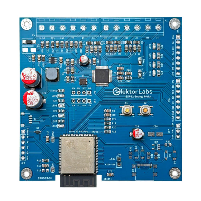
Elektor Labs Elektor ESP32 Energy Meter
The Elektor ESP32 Energy Meter is a device designed for real-time energy monitoring and smart home integration. Powered by the ESP32-S3 microcontroller, it offers robust performance with modular and scalable features. The device uses a 220 V-to-12 V step-down transformer for voltage sampling, ensuring galvanic isolation and safety. Its compact PCB layout includes screw-type terminal blocks for secure connections, a Qwiic connector for additional sensors, and a programming header for direct ESP32-S3 configuration. The energy meter is compatible with single-phase and three-phase systems, making it adaptable for various applications. The energy meter is simple to set up and integrates with Home Assistant, offering real-time monitoring, historical analytics, and automation capabilities. It provides accurate measurements of voltage, current, and power, making it a valuable tool for energy management in homes and businesses. Features Comprehensive Energy Monitoring: Get detailed insights into your energy usage for smarter management and cost savings. Customizable Software: Tailor functionality to your needs by programming and integrating custom sensors. Smart Home Ready: Compatible with ESPHome, Home Assistant, and MQTT for full Smart Home integration. Safe & Flexible Design: Operates with a 220 V-to-12 V step-down transformer and features a pre-assembled SMD board. Quick Start: Includes one Current Transformer (CT) sensor and access to free setup resources. Specifications Microcontroller ESP32-S3-WROOM-1-N8R2 Energy Metering IC ATM90E32AS Status Indicators 4x LEDs for power consumption indication2x Programmable LEDs for custom status notifications User Input 2x Push buttons for user control Display Output I²C OLED display for real-time power consumption visualization Input Voltage 110/220 V AC (via step-down transformer) Input Power 12 V (via step-down transformer or DC input) Clamp Current Sensor YHDC SCT013-000 (100 A/50 mA) included Smart Home Integration ESPHome, Home Assistant, and MQTT for seamless connectivity Connectivity Header for programming, Qwiic for sensor expansion Applications Supports single-phase and three-phase energy monitoring systems Dimensions 79.5 x 79.5 mm Included 1x Partly assembled board (SMDs are pre-mounted) 2x Screw terminal block connectors (not mounted) 1x YHDC SCT013-000 current transformer Required Power transformer not included Downloads Datasheet (ESP32-S3-WROOM-1) Datasheet (ATM90E32AS) Datasheet (SCT013-000) Frequently Asked Questions (FAQ) From Prototype to Finished Product What started as an innovative project to create a reliable and user-friendly energy meter using the ESP32-S3 microcontroller has evolved into a robust product. Initially developed as an open-source project, the ESP32 Energy Meter aimed to provide precise energy monitoring, smart home integration and more. Through meticulous hardware and firmware development, the energy meter now stands as a compact, versatile solution for energy management.
€ 79,95€ 64,95
Members identical
-
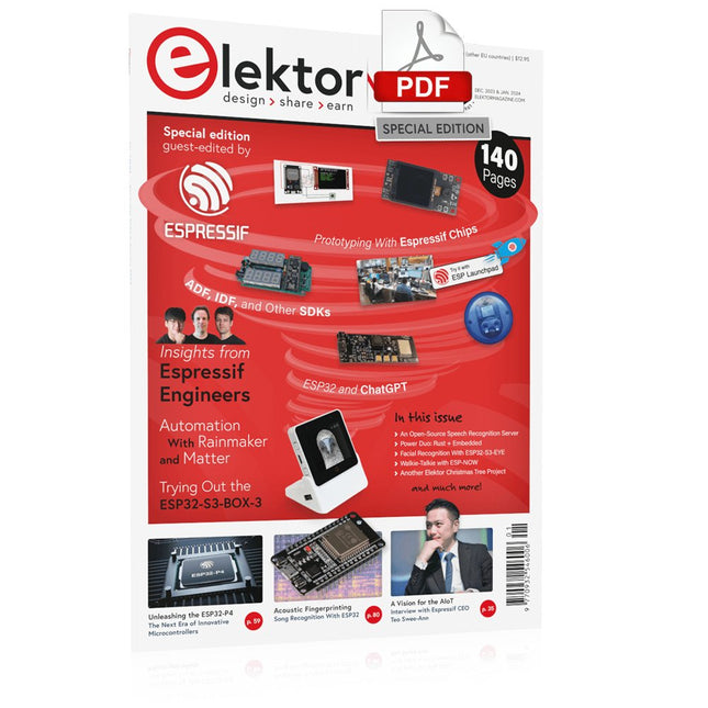
Elektor Digital Elektor Espressif Guest Edition (PDF)
Elektor GREEN and GOLD members can download their digital edition here. Not a member yet? Click here. Accelerating IoT Innovation A Color E-Ink Wi-Fi Picture Frame ESP-Launchpad TutorialFrom Zero to Flashing in Minutes ESP32 and ChatGPTOn the Way to a Self-Programming System… Walkie-Talkie with ESP-NOWNot Quite Wi-Fi, Not Quite Bluetooth! From Idea to Circuit with the ESP32-S3A Guide to Prototyping with Espressif Chips AIoT Chip InnovationAn Interview With Espressif CEO Teo Swee-Ann Simulate ESP32 with WokwiYour Project’s Virtual Twin Trying Out the ESP32-S3-BOX-3A Comprehensive AIoT Development Platform Electronics Workspace EssentialsInsights and Tips From Espressif Engineers The ESP RainMaker StoryHow We Built “Your” IoT Cloud Assembling the Elektor Cloc 2.0 KitAn Elektor Product Unboxed by Espressif Unleashing the ESP32-P4The Next Era of Microcontrollers Rust + EmbeddedA Development Power Duo Who Are the Rust-Dacious Embedded Developers?How Espressif is Cultivating Embedded Rust for the ESP32 Espressif’s Series of SoCs Building a PLC with Espressif SolutionsWith the Capabilities and Functionality of the ISOBUS Protocol The ESP32-S3 VGA BoardBitluni’s Exciting Journey Into Product Design Acoustic Fingerprinting on ESP32Song Recognition With Open-Source Project Olaf Circular Christmas Tree 2023A High-Tech Way to Celebrate the Holiday Season A Simpler and More Convenient LifeAn Amateur Project Based on the Espressif ESP8266 Module How to Build IoT Apps without Software ExpertiseWith Blynk IoT Platform and Espressif Hardware Building a Smart User Interface on ESP32 Quick & Easy IoT Development with M5Stack Prototyping an ESP32-Based Energy Meter A Value-Added Distributor for IoT and More In-Depth Insights: Interview With Arduino on the Nano ESP32Alessandro Ranellucci and Martino Facchin Discuss Espressif Collaboration Your AIoT Solution ProviderInsights From Espressif Streamlining MCU Development With ESP-IDF Privilege Separation An Open-Source Speech Recognition Server……and the ESP BOX The Thinking EyeFacial Recognition and More Using the ESP32-S3-EYE ESP32-C2-Based Coin Cell SwitchDesign and Performance Evaluation The Smart Home Leaps Forward with MatterUnlocking Smart Home IoT Potential Tech the Future: Where Is Smart Home IoT Headed?
€ 7,50
-
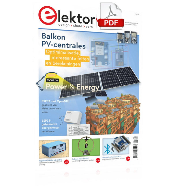
Elektor Digital Elektor Januari/Februari 2024 (PDF)
Elektor GREEN en GOLD leden kunnen deze uitgave hier downloaden. Nog geen lid? Klik hier om een lidmaatschap af te sluiten. Project-update: ESP32-gebaseerde energiemeterwe gaan verder met het prototype Optimalisatie van balkon PV-centralesoverwegingen, interessante feiten en berekeningen ESP32 met OpenDTU voor balkoncentralesgegevens van kleine omvormers via MCU’s uitlezen Regelbare lineaire labvoeding0...50 V / 0...2 A + dubbele symmetrische voeding Energieopslag – vandaag en morgeneen vraaggesprek met Simon Engelke 2024: een AI-odysseehet houdt nog lang niet op Bluetooth LE op de STM32meetwaarden op afstand uitlezen Mensvriendelijk slim keuken-voorraadsysteem MAUI: programmeren voor PC, tablet en smartphonehet nieuwe framework in theorie en praktijk ChatMagLevkunstmatig intelligente levitatie Eenvoudige PV-regelaarbouw je eerste, volledig functionele PV-energiebeheersysteem Koude-kathode-buizenvreemde onderdelen Uit het leven gegrepennostalgie Alle begin......bekijkt de FET CAN-bus voor de Arduino UNO R4: een tutorialtwee UNO R4’s nemen de bus! Elektor infographicvoeding en energie Vergelijking van vermogensdichtheid en vermogensefficiëntie Aluminium elektrolytische condensatorenstoringspotentieel in audiotechnologie USB testen en metenmet de Fnirsi FNB58 De Pixel Pump pick&place-tooleenvoudiger handmatige assemblage van SMT-printen Oost West Lab Bestnog niet zo lang geleden, in een land heel ver van hier... “In de wereld van ethiek in elektronica kunnen zelfs kleine stappen een aanzienlijke invloed hebben.” Ethiek in elektronicade OECD Guidelines en het Lieferkettensorgfaltspflichtengesetz Chadèche: slimme NiMH-(ont)laderlezersproject in het kort Project 2.0correcties, updates en brieven van lezers
€ 9,95
-
Elektor Digital Elektor January/February 2020 (PDF)
Elektor Magazine EN January/February 2020 (PDF)
€ 7,50
-

Elektor Digital Elektor January/February 2021 (PDF)
Elektor Magazine EN January/February 2021 (PDF)
€ 7,50
-
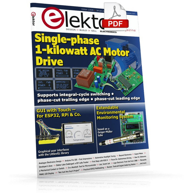
Elektor Digital Elektor January/February 2022 (PDF)
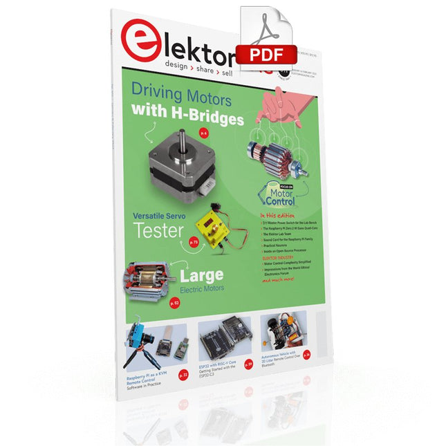
DRIVING MOTORS WITH H-BRIDGESAn Introduction to DC, Stepper, and Brushless Motors THE ELEKTOR LAB TEAMOur Approach, Preferred Tools, and More RASPBERRY PI AS A KVM REMOTE CONTROLPi-KVM Software Test IQAUDIO CODEC ZEROA Sound Card for the Raspberry Pi Family THE PIKVM PROJECT AND LESSONS LEARNEDInterview with Maxim Devaev (Developer, PiKVM) AUTONOMOUS VEHICLE WITH 2D LIDARESP32 Pico Interprets Data from the Lidar Module THE RASPBERRY PI ZERO 2 W GOES QUAD-CORE NOTES FROM THE 2021 WORLD ETHICAL ELECTRONICS FORUM MOTOR CONTROLHow the Complexity of Motor Control Is Simplified LARGE ELECTRIC MOTORSBasic Principles and Useful Information GETTING STARTED WITH THE ESP32-C3 RISC-V MCU PROTECT YOURSELF AND OTHERS!DIY Master Power Switch for the Lab Bench CREATE GUIS WITH PYTHON (PART 2)Spy name chooser PRODUCTRONICA FAST FORWARD 2021 WINNERSExciting Technologies and Creative Engineering Solutions VERSATILE SERVO TESTERCheck Behavior When There’s No Datasheet MODBUS OVER WLAN (PART 2)Software for the Modbus TCP WLAN Module UNDERSTANDING THE NEURONS IN NEURAL NETWORKS (PART 3)Practical Neurons INSIDE AN OPEN-SOURCE PROCESSORSample Chapter: Lattice and Xilinx FPGA Results STARTING OUT IN ELECTRONICSWe Are Not Yet Done with the Coil ERR-LECTRONICSCorrections, Updates and Readers’ Letters COLOR TO SOUNDHow to Read Out a Color Sensor via I2C BATTLAB-ONEMeasure and Optimize the Battery Life of IoT Devices SIMPLE EARTH-LEAKAGE TRACERTesting Isolation of Mains Supply POVERTY AND ELECTRONICSSustainable Development Goal 1 HEXADOKUThe Original Elektorized Sudoku
€ 7,50
-
Elektor Digital Elektor January/February 2023 (PDF)
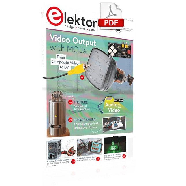
Elektor GREEN and GOLD members can download their digital edition here. Not a member yet? Click here. For Eyes and Ears Video Output with Microcontrollers (1)Composite Video electronica 2022News from the world’s leading electronics trade show ESP32 CameraSo Simple, It Doesn’t Even Have to Use Wi-Fi ATX Power Supply for Raspberry Pi 32 Ω Headphone AmplifierSimple But High-Quality 3-Chip Solution SDR Radio-Controlled clocksFive Time Signals, Six Displays Starting Out in ElectronicsSpecial Diodes From Life's ExperienceMusings on the Quality of Things Reverse-Engineering a Bluetooth Low Energy LED BadgeHow to Control a BLE Device with a Python Script MakePython ESP32 Development KitEverything in a Box THD Measurement with an Oscilloscope and FFTEasily Calculate the Distortion Factor All-Seeing MachinesThe Technology Behind Today’s Industrial Vision Systems Infographics The Evolution of Voice and Audio Control for Electronic Devices WEEF 2022 in Review FFWD electronica 2022 in ReviewInnovators Did Not Fail to Impress The TubeAn Unusual Tube Amplifier Biomaterial in Electronics: Ready or Not Opera Cake Antenna Switch for HackRF OneConnect Up To Eight Antennas To Your SDR Engineering with Arduino and MoreAn Interview with Author Ashwin Pajankar LiDAR Precision GaugeMeasure up to 12 Meters Audio Signals and the ESP32The ESP-ADF Environment in Practice Elektor Fortissimo-100 Power Amplifier Kit Using Light for Sound EffectsLDR-Based Voltage-Controlled 24 dB/oct Synthesizer Filter Elektor High-Power AF AmplifierThe Loudest of Them All! HomeLab ToursA Volumetric Display Made in Canada Err-lectronicsCorrections, Updates and Readers’ Letters Hexadoku
€ 7,50
-

Elektor Digital Elektor January/February 2024 (PDF)
Elektor GREEN and GOLD members can download their digital edition here. Not a member yet? Click here. Project Update: ESP32-Based Energy MeterNext Steps in Prototyping Optimizing Balcony Power PlantsConsiderations, Interesting Facts, and Calculations ESP32 With OpenDTU for Balcony Power PlantsRead Data from Small Inverters Via MCUs Variable Linear Power Supply Ensemble0…50 V / 0…2 A + Dual Symmetrical Supply Energy Storage Today and TomorrowAn Interview With Simon Engelke 2024: An AI OdysseyIt’s Not Letting Up Bluetooth LE on the STM32A Way to Read Measurements Remotely Human-Centric Smart Kitchen Grocery Container MAUI: Programming for PC, Tablet, and SmartphoneThe New Framework in Theory and Practice ChatMagLevThe AI Way of Levitation Simple PV Power RegulatorBuild Your First, Fully Functional PV Energy Management System Cold-Cathode DevicesPeculiar Parts, the Series From Life’s ExperienceNostalgia Starting Out in Electronics……Looking at FETs CAN Bus Tutorial for the Arduino UNO R4Two UNO R4s Hop on the Bus! Infographics: Power & Energy Comprehensive Design and Development SupportArrow Engineering Services Comparing Power Density and Power Efficiency Aluminium Electrolytic CapacitorsInterference Potential in Audio Technology USB Test and MeasurementThe Fnirsi FNB58 The Pixel Pump Pick-and-Place ToolSimplifying Manual SMT Board Assembly HomeLab ToursNot So Long Ago, in a Far-Away Country... “In the world of ethics in electronics, even small steps can make a significant impact.” Ethics in ElectronicsThe OECD Guidelines and Germany’s Supply Chain Due Diligence Act Chadèche: Smart Ni-MH Charger/DischargerA Reader’s Project in Brief Err-lectronicsCorrections, Updates and Readers’ Letters
€ 7,50
-
Elektor Digital Elektor January/February 2025 (PDF)
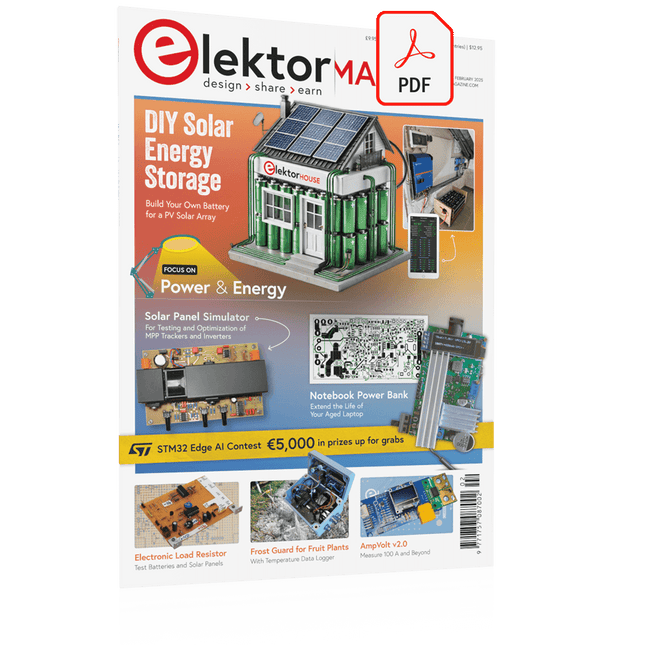
Elektor GREEN and GOLD members can download their digital edition here. Not a member yet? Click here. DIY Solar Energy StorageBuild Your Own Energy Store for a PV Solar Array Solar Module SimulatorA Solution for Testing and Optimizing MPP Trackers and Inverters The STM32 Edge AI ContestExplore the new STM32N6 and Compete for a Share of €5,000 in Prizes! Widening the BandgapWhy There Is So Much Interest in SiC and GaN Notebook Power BankExtend the Life of Your Aged Laptop Medical RobotsOvercoming Technical and Regulatory Hurdles Frost Guard for Fruit Plants With Temperature Data Logger The Analog ThingThe Arduino of Analog Computing? Energy Saving Relay DriverSaves 90% of Relay Drive Power Improving the ET5410A+ DC loadKeep Cool and Be Quiet, Please electronica 2024 in Review Electromagnetic CompatibilityEMC in a Nutshell! Starting Out in Electronics……Filters Actively Reducing Power Dissipation With Dropping CapacitorsA Clever Use of Capacitive Reactance The Affordable MCP4725 12-Bit Digital-to-Analog ConverterAn EEPROM Feature Enables Safe Switch-On Behavior Fnirsi LCR-ST1 Smart LCR SMD Tweezers Raspberry Pi-Based Private Test & Measurement LabFirst Things First: The ADC Electronic Load ResistorAn Out-of-the-Box Project 2025: An AI OdysseySome Projects to See in the New Year AmpVolt v2.0 Project Update100 Amps and Beyond! Err-lectronicsCorrections, Updates, and Readers’ Letters Unveiling Ethical TransparencyInsights from Ethics in Electronics’s 2024 Survey Elektor Audio DSP FX Processor Board (2)Creating Applications
€ 7,50
-
Elektor Digital Elektor July/August 2020 (PDF)
Elektor Magazine EN July/August 2020 (PDF)
€ 7,50


