Products
-
Elektor Digital Elektor November/December 2021 (PDF)
IMAGE PROCESSING WITH THE NVIDIA JETSON NANO (PART 2)Image Recognition Using Edge Impulse ELEKTOR JUMPSTARTER NEWSUpcoming Campaigns AN OPEN-SOURCE GPS TRACKING PLATFORMTraccar Maps Vehicle Tracking Without the Need for a Third-Party Cloud Server JOY-IT LCR-T7 MULTI-FUNCTION TESTERTesting Passives, Discrete Semiconductors and IR Remote Controls NOISE SYNTHESIZERFrom Noise to Music with the PRBSynth1 STARTING OUT IN ELECTRONICSEasier than Imagined! ... Continuing with the Coil UNDERSTANDING THE NEURONS IN NEURAL NETWORKS (PART 2)Logical Neurons ISSUES WITH SECURITY? FIGHT FIRE WITH FIRE!Flashbulb-Protected Analogue Memory Add-on For the Tamper-Evident Box LCR METER POSTER BLUETOOTH BEACONS IN PRACTICEBeacons Light the Way Ahead C PROGRAMMING ON RASPBERRY PICommunicating over Wi-Fi (Sample Chapter) EMC PRE-COMPLIANCE TEST FOR YOUR DC-POWERED PROJECT (PART 2)The Hardware and How to Use It HANDS ON THE PARALLAX PROPELLER 2 (PART 5)Inside the Smart Pin MODBUS OVER WLAN (PART 1)Hardware and Programming HOMELAB TOURSWhere the Junior Computer Is Brought to Life Again BUILD YOUR OWN HIGH-PRECISION CALIBRATOR-10 V to +10 V, 0 to 40 mA, 0.001% ARDUINO NANO RP2040 CONNECTRaspberry Pi RP2040 + Wi-Fi + Bluetooth THE PHYSICAL BODY OF ARTIFICIAL INTELLIGENCE ERR-LECTRONICSCorrections, Updates and Readers’ Letters CREATE GUIS WITH PYTHONIntroducing guizero CO2 METER KIT FOR THE CLASSROOMAn ESP8266-Based Device from the University of Applied Sciences Aachen NOSTALGIC MK484 MW/LW RADIO...Always Fun to Build! ELEKTOR @ 60Let There Be Light! HEXADOKUThe Original Elektorized Sudoku
€ 7,50
-

Elektor Digital Elektor November/December 2022 (PDF)
Elektor GREEN and GOLD members can download their digital edition here. Not a member yet? Click here. High-End from the Elektor Lab Fortissimo-100 High-End AmplifierFully symmetrical audio output stage and 100/190 W Checking the Frequency of Tuned Circuits and CrystalsTips & Tricks, Best Practices and Other Useful Information PCB Tips and Tricks Soldering – So What?A Closer Look at Current Soldering Technology Low-Latency Bluetooth Garage Door ControlTake Control with Short BLE Messages from a Smartphone Ideal Diode ControllerDiode Circuits with Low Power Dissipation LED Garlands with ESP32 and FreeRTOSFlashing and Variable Brightness Starting Out in Electronics……Cheerfully Continues Zenering FM/DAB+ ReceiverThe Best of Both Worlds From Life’s ExperienceElectronica Obscura Tracing the Cause of Software Bugs WirelesslyCircular Buffer and Webserver on the ESP32 Did Covid Cause a Boost in Engineering Innovation?Innovative Components and Solutions from 2022 Ersa i-CON TRACE – The IoT Soldering Station for Makers Infographics What Are We Going to Do with All This Compute? How to Drive Ynvisible’s E-Paper Display All-Time Innovation with InnoFaithQ&A with Walter Arkesteijn Industrial AutomationEasy and scalable IoT-Retrofitting Next Generation Oscilloscopes for Accelerated InsightRohde & Schwarz introduces the R&S MXO 4 series Low Profile Linear Connectors Solve Multi-Signal Data Management Smart – Innovative – Cost-EfficientGateMate FPGAs Developed and Manufactured in Germany Tools to Support Low-Cost Sensor Development PolyfusesPeculiar Parts, the Series Isolated Analog Output for Arduino Uno HomeLab Tours... Discovers the Theremin electronica fast forward 2022 - powered by ElektorLineup and Timetable Radio Direction FindingTracking Down Lost Wireless Weather Sensors Estimate an IC's Internal NoiseA Simple Method Ethics in ActionPowered by WEEF No Ethics, No Sustainable BusinessAn Interview with Professor Stefan Heinemann The 2023 WEEF Index Filter SoftwareDesign Tools for Analog Filters TV-B-Gone!... Or At Least B-OFF RP2040-Based Air Quality Measurement elekterminal Kickstart to Python 3Sample Chapter: Digital Image Processing and Wand Library SOLARPUNKA Brighter Future Ahead Hexadoku
€ 7,50
-
Elektor Digital Elektor November/December 2023 (PDF)
Elektor GREEN and GOLD members can download their digital edition here. Not a member yet? Click here. The Raspberry Pi 5A Huge Improvement From Its Predecessor AI in the Electronics LabGoogle Bard and Flux Copilot Put to the Test Arduino Nano Waveform GeneratorNano + Code = Function Generator Solar-Powered Christmas GarlandAn Eco-Friendly Solution for Garnishing Your Balcony USB Killer DetectorBetter Safe Than Sorry A Simple CNCed EnclosureWith Autodesk Fusion 360 for Personal Use Low-Volume Board ProductionWith and without Assembly IoT Simulation Simplified with WokwiDeveloper Uri Shaked on Design, Software, and More A Bare-Metal Programming Guide (Part 3)CMSIS Headers, Automatic Testing, and a Web Server LoRa, a Swiss Army Knife (2)The Hardware and Software MEMS Microphone Design and Construction Tools to Try Before You SolderSimulation and 3D Modeling Tools That Can Be Used for Free New Tools From Microchip!PICkit 5 and MPLAB ICD 5 Available Now! Rapid Prototyping of Flexible, Stretchable ElectronicsHow the Voltera NOVA Speeds Up Innovation in Wearable Electronic Systems Galvanic IsolationUsing Phototransistor Optocouplers Successfully The Complex Solution or the Anybus Solution?Embedded Industrial Ethernet in 2 Days Rather Than Many Months Your Essential DFM ChecklistHow to Start Designing for Manufacture 3D Printing FilamentsTypes, Features and Use in Prototyping Specialists for Effective Signal Analysis from ELF to EHF BandAaronia’s latest real-time SPECTRAN® V6 series spectrum analyzers Challenges of DFM Analysis for Flex and Rigid-Flex Design Setting Up an SMT Line The Right Combination for a Reliable Assembly Revolutionizing IndustriesThe Rise of Autonomous Mobile Robots (AMRs) Evolved for More ChallengesRohde & Schwarz Adds Eight-Channel R&S MXO 5 to Next-Generation Oscilloscopes Starting Out in Electronics……Amplifying Differences Mini Reflow PlateFor Assembling or Repairing Small SMD Circuits Don’t Start with a Prototype – Start with a Pretotype!Check That a Market Exists for Your Product Before Warming Your Soldering Iron 2023: An AI OdysseyGetting Help Designing a Physical Project Brussels Is InnovatingSupport for Deep Tech
€ 7,50
-
Elektor Digital Elektor November/December 2024 (PDF)
Elektor GREEN and GOLD members can download their digital edition here. Not a member yet? Click here. Audio DSP FX Processor BoardPart 1: Features and Design 50 Years of Elektor in English KiCad 8Top New and Updated Features Elektor MultiCalculator KitAn Arduino-Based Calculator Kit for Electronic Purposes Low-Cost GNSS RTK SystemsWith Centimeter-Level Degree of Accuracy PCB Layout and SafetyHints for a Safe, Long-Life Design of Your Boards Opamp TesterFor Audio and Other Applications Project Update #4: ESP32-Based Energy MeterEnergy Monitoring with MQTT Real-Time Spectrum Analyzer with Waveguide Technology and Multi-Interface PCsAaronia Establishes New Product Segment and Presents First Prototypes at Electronica in Munich Applications of Ynvisible’s E-paper DisplaysTransform Businesses and Shape the Future SMT InductorsCoils and Ferrites — Selection Made Easy Arrow Electronics to Showcase Innovative Technologies at electronica 2024 Using EMI Shielding to Achieve Electromagnetic Compatibility Compliance The Ultimate Tool for Every Electronics EnthusiastUnlock Endless Possibilities with Red Pitaya and 1,000+ Click Boards™ V-LD1 Distance Radar Module Siglent Presents Its New Vector Network Analyzer Platform SNA6000A HDI in the MiddleA New Cost-Effective PCB Pooling Service for Tiny BGAs Remote Access IoT LabOne and Only Solution for Remote Learning and Development in Embedded Industry Challenges of DFM Analysis for Flex and Rigid-Flex Design From Life's ExperienceMicrotechnophobia 3D Christmas TreeA 3D PCB with a Low-Cost, 32-bit Microcontroller Starting Out in Electronics……Continues with the Opamp! An Autonomous Sensor Node (Project Update #1)Reducing Idle Power Consumption with External RTC and Power Switch 2024: An AI OdysseyA Look Back at the Future LED Displays with the MAX7219A Hands-On Approach to a Great Chip Err-lectronicsCorrections, Updates, and Readers’ Letters VibroTactile GlovesA Breakthrough for Parkinson’s Patients
€ 7,50
-

Elektor November/December 2025 (EN)
Elektor GREEN and GOLD members can download their digital edition here. Not a member yet? Click here. Relio v1.0 - Presence Detection and Remote ControlA Matter-Enabled Smart Controller for AC Appliances Designing Better PCBsA Practical Guide for Professionals and Makers KiCad 9Top New and Updated Features Precision Picoammeter (1)With Curve Tracer Functionality Down to the pA range! Christmas Star 2025A Star Is Soldered 100 mV Continuity Tester Who’s Pushing the Boundaries of European Electronics?Companies to Watch productronica 2025: What’s New in Electronics Development and Production Automation to Tackle Reshoring Manufacturing, Tariffs and Labour Shortages Beyond Future ProofCircularity in Electronics Passive ComponentsLow-Loss Inductors Enabling High-Efficiency DC/DC Converters How Desktop Manufacturing Machines Are Democratizing PCB Production Starting Out in Electronics...Needs Power UHD Displays Driven with EaseYour Guide to Easily Put Various TFT-LCDs Into Operation Quickly Soldering in 2025Practical Soldering Tips Straight from the Workbench SimulIDEAn All-in-One Tool for Circuit Prototyping 2025: An AI OdysseyFrom Autocomplete to Colleague Wordy Christmas TreeA Festive Electronics Project with a Linguistic Twist Err-lectronicsCorrections, Updates, and Readers’ Letters Analog Pipeline DistortionA Cool Audio Effect For Guitars and Other Instruments ESP32 Audio Transceiver Board (Part 3)Stereo Transmission and Dual Radio
€ 14,90
-

Elektor Digital Elektor November/December 2025 (PDF) EN
Elektor GREEN and GOLD members can download their digital edition here. Not a member yet? Click here. Relio v1.0 - Presence Detection and Remote ControlA Matter-Enabled Smart Controller for AC Appliances Designing Better PCBsA Practical Guide for Professionals and Makers KiCad 9Top New and Updated Features Precision Picoammeter (1)With Curve Tracer Functionality Down to the pA range! Christmas Star 2025A Star Is Soldered 100 mV Continuity Tester Who’s Pushing the Boundaries of European Electronics?Companies to Watch productronica 2025: What’s New in Electronics Development and Production Automation to Tackle Reshoring Manufacturing, Tariffs and Labour Shortages Beyond Future ProofCircularity in Electronics Passive ComponentsLow-Loss Inductors Enabling High-Efficiency DC/DC Converters How Desktop Manufacturing Machines Are Democratizing PCB Production Starting Out in Electronics...Needs Power UHD Displays Driven with EaseYour Guide to Easily Put Various TFT-LCDs Into Operation Quickly Soldering in 2025Practical Soldering Tips Straight from the Workbench SimulIDEAn All-in-One Tool for Circuit Prototyping 2025: An AI OdysseyFrom Autocomplete to Colleague Wordy Christmas TreeA Festive Electronics Project with a Linguistic Twist Err-lectronicsCorrections, Updates, and Readers’ Letters Analog Pipeline DistortionA Cool Audio Effect For Guitars and Other Instruments ESP32 Audio Transceiver Board (Part 3)Stereo Transmission and Dual Radio
€ 9,50
-
Elektor Labs Elektor One-armed Bandit
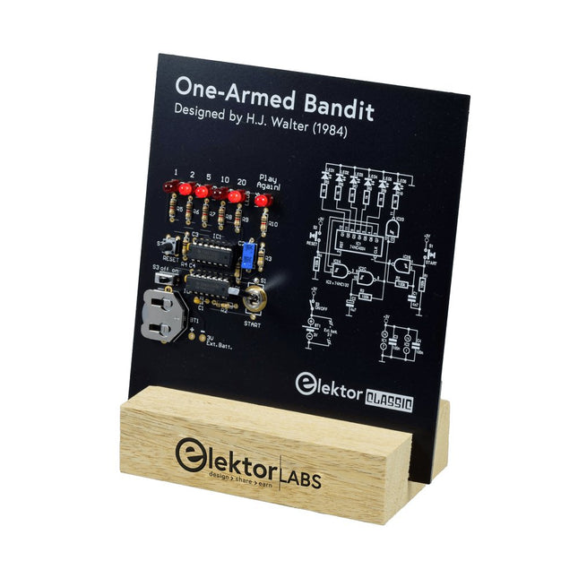
Pull Down Lever For Highest Score! This Elektor Circuit Classic from 1984 shows a playful application of CMOS 400x series logic ICs in combination with LEDs, a highly popular combination at the time. The project imitates a spinning-digit type slot machine. The Game To play the game, first agree on the number of rounds. Player 1 actuates the switch lever as long as desired and releases it. The LEDs then show the score which is the sum of the 50-20-10-5 digits lit up. If the Play Again! LED lights, Player 1 has another, “free” round. If not, it’s Player 2’s turn. The players keep tab of their scores, and the highest score wins. Features LEDs Indicate Score Multi-Player and Play Again! Elektor Heritage Circuit Symbols Tried & Tested by Elektor Labs Educational & Geeky Project Through-Hole Parts Only Included Printed Circuit Board All Components Wooden Stand Bill of Materials Resistors (5%, 250 mW) R1,R2,R3,R4 = 100kΩ R5,R6,R7,R8,R9,R10 = 1kΩ Capacitors C1 = 4.7nF, 10%, 50V, 5mm C2 = 4.7μF, 10%, 63V, axial C3,C4 = 100nF, 10 %, 50V, ceramic X7R, 5mm Semiconductors LED1-LED6 = red, 5mm (T1 3/4) IC1 = 74HC4024 IC2 = 74HC132 Miscellaneous S1 = switch, toggle, 21mm lever, SPDT, momentary S2 = switch, tactile, 24V, 50mA, 6x6mm S3 = switch, slide, SPDT IC1,IC2 = IC socket, DIP14 BT1 = PCB-mount CR2032 battery retainer clip Desktop Stand PCB 230098-1 Not included: BT1 = CR2032 coin cell battery
€ 39,95€ 15,98
Members identical
-
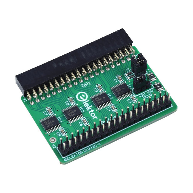
Elektor Labs Elektor Raspberry Pi Buffer Board
When you experiment with the Raspberry Pi on a regular basis and you connect a variety of external hardware to the GPIO port via the header you may well have caused some damage in the past. The Elektor Raspberry Pi Buffer Board is there to prevent this! The board is compatible with Raspberry Pi Zero, Zero 2 (W), 3, 4, 5, 400 and 500. All 26 GPIOs are buffered with bi-directional voltage translators to protect the Raspberry Pi when experimenting with new circuits. The PCB is intended to be inserted in the back of Raspberry Pi 400/500. The connector to connect to the Raspberry Pi is a right angled 40-way receptacle (2x20). The PCB is only a fraction wider. A 40-way flat cable with appropriate 2x20 headers can be connected to the buffer output header to experiment for instance with a circuit on a breadboard or PCB. The circuit uses 4x TXS0108E ICs by Texas Instruments. The PCB can also be put upright on a Raspberry Pi. Downloads Schematics Layout
€ 34,95€ 29,95
Members identical
-
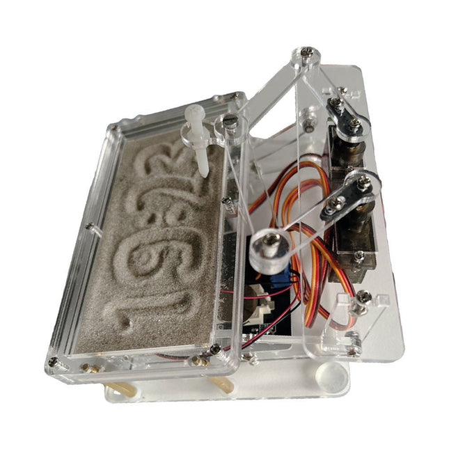
Elektor Labs Elektor Sand Clock for Raspberry Pi Pico
Raspberry Pi-based Eye Catcher A standard sand clock just shows how time passes. In contrast, this Raspberry Pi Pico-controlled sand clock shows the exact time by “engraving” the four digits for hour and minute into the layer of sand. After an adjustable time the sand is flattened out by two vibration motors and everything begins all over again. At the heart of the sand clock are two servo motors driving a writing pen through a pantograph mechanism. A third servo motor lifts the pen up and down. The sand container is equipped with two vibration motors to flatten the sand. The electronic part of the sand clock consists of a Raspberry Pi Pico and an RTC/driver board with a real-time clock, plus driver circuits for the servo motors. A detailed construction manual is available for downloading. Features Dimensions: 135 x 110 x 80 mm Build time: approx. 1.5 to 2 hours Included 3x Precut acrylic sheets with all mechanical parts 3x Mini servo motors 2x Vibration motors 1x Raspberry Pi Pico 1x RTC/driver board with assembled parts Nuts, bolts, spacers, and wires for the assembly Fine-grained white sand
€ 49,95€ 39,95
Members identical
-

Elektor Labs Elektor Sand Clock for Raspberry Pi Pico (incl. Laser Head Upgrade)
This bundle contains the popular Elektor Sand Clock for Raspberry Pi Pico and the new Elektor Laser Head Upgrade, offering even more options for displaying the time. Not only can you "engrave" the current time in sand, you can now alternatively write it on a glow-in-the-dark foil or create green drawings. Contents of the bundle Elektor Sand Clock for Raspberry Pi Pico (normal price: €50) Elektor Laser Head Upgrade for Sand Clock (normal price: €35) Elektor Sand Clock for Raspberry Pi (Raspberry Pi-based Eye Catcher) A standard sand clock just shows how time passes. In contrast, this Raspberry Pi Pico-controlled sand clock shows the exact time by "engraving" the four digits for hour and minute into the layer of sand. After an adjustable time the sand is flattened out by two vibration motors and everything begins all over again. At the heart of the sand clock are two servo motors driving a writing pen through a pantograph mechanism. A third servo motor lifts the pen up and down. The sand container is equipped with two vibration motors to flatten the sand. The electronic part of the sand clock consists of a Raspberry Pi Pico and an RTC/driver board with a real-time clock, plus driver circuits for the servo motors. A detailed construction manual is available for downloading. Features Dimensions: 135 x 110 x 80 mm Build time: approx. 1.5 to 2 hours Included 3x Precut acrylic sheets with all mechanical parts 3x Mini servo motors 2x Vibration motors 1x Raspberry Pi Pico 1x RTC/driver board with assembled parts Nuts, bolts, spacers, and wires for the assembly Fine-grained white sand Elektor Laser Head Upgrade for Sand Clock The new Elektor Laser Head transforms the Sand Clock into a clock that writes the time on glow-in-the-dark film instead of sand. In addition to displaying the time, it can also be used to create ephemeral drawings. The 5 mW laser pointer, with a wavelength of 405 nm, produces bright green drawings on the glow-in-the-dark film. For best results, use the kit in a dimly lit room. Warning: Never look directly into the laser beam! The kit includes all the necessary components, but soldering three wires is required. Note: This kit is also compatible with the original Arduino-based Sand Clock from 2017. For more details, see Elektor Magazine 1-2/2017 and Elektor Magazine 1-2/2018.
€ 84,95€ 69,95
Members identical
-

Elektor Digital Elektor Select: Embedded & AI (PDF)
This collection features the best of Elektor Magazine's articles on embedded systems and artificial intelligence. From hands-on programming guides to innovative AI experiments, these pieces offer valuable insights and practical knowledge for engineers, developers, and enthusiasts exploring the evolving intersection of hardware design, software innovation, and intelligent technology. Contents Programming PICs from the Ground UpAssembler routine to output a sine wave Object-Oriented ProgrammingA Short Primer Using C++ Programming an FPGA Tracking Down Microcontroller Buffer Overflows with 0xDEADBEEF Too Quick to Code and Too Slow to Test? Understanding the Neurons in Neural NetworksEmbedded Neurons MAUI Programming for PC, Tablet, and SmartphoneThe New Framework in Theory and Practice USB Killer DetectorBetter Safe Than Sorry Understanding the Neurons in Neural NetworksArtificial Neurons A Bare-Metal Programming Guide Part 1: For STM32 and Other Controllers Part 2: Accurate Timing, the UART, and Debugging Part 3: CMSIS Headers, Automatic Testing, and a Web Server Introduction to TinyMLBig Is Not Always Better Microprocessors for Embedded SystemsPeculiar Parts, the Series FPGAs for BeginnersThe Path From MCU to FPGA Programming AI in Electronics DevelopmentAn Update After Only One Year AI in the Electronics LabGoogle Bard and Flux Copilot Put to the Test ESP32 and ChatGPTOn the Way to a Self-Programming System… Audio DSP FX Processor Board Part 1: Features and Design Part 2: Creating Applications Rust + EmbeddedA Development Power Duo A Smart Object CounterImage Recognition Made Easy with Edge Impulse Universal Garden LoggerA Step Towards AI Gardening A VHDL ClockMade with ChatGPT TensorFlow Lite on Small MicrocontrollersA (Very) Beginner’s Point of View Mosquito DetectionUsing Open Datasets and Arduino Nicla Vision Artificial Intelligence Timeline Intro to AI AlgorithmsPrompt: Which Algorithms Implement Each AI Tool? Bringing AI to the Edgewith ESP32-P4 The Growing Role of Edge AIA Trend Shaping the Future
€ 9,95
Members € 8,96
-
Elektor Digital Elektor September/October 2020 (PDF)
Elektor Magazine EN September/October 2020 (PDF)
€ 7,50
-
Elektor Digital Elektor September/October 2021 (PDF)
UNDERSTANDING THE NEURONS IN NEURAL NETWORKS (PART 1)Artificial Neurons EMC PRE-COMPLIANCE TEST FOR YOUR DC-POWERED PROJECT (PART 1)Dual DC LISN ELECTRONIC LOAD FOR DC AND ACUp to 400 V and 10 A (Peak) STARTING OUT IN ELECTRONICSEasier Than Imagined! ...Taking on the Choke! IMAGE PROCESSING WITH THE NVIDIA JETSON NANO (PART 1)The Hardware and Software AN IN-DEPTH LOOK AT MAINS TRANSFORMERSHow Do They Behave When They Are Switched On and Off? YES WE CAN WITH PICAN 3A CAN Bus HAT for the Raspberry Pi 4 BALCONY POWER PLANTDIY Solar Balcony = Speedy Payback! IMAGING AND VIDEO-STREAMING WITH A RASPBERRY PI 4The Raspberry Pi High-Quality Camera in Practice USING DISPLAYS IN RASPBERRY PI PROJECTSSample Chapter: Organic Light Emitting Diode Displays (OLED) HANDS ON THE PARALLAX PROPELLER 2 (PART 4)Sending Strings ELEKTOR @ 60A Look Back at Previous Septembers HOMELAB TOURSIn the Friesian Countryside, Where the Tubes Bloom ... HYBRIDSPeculiar Parts, the series A COMPASS ROSE USING THE GY-271Or Why We Move in Figures of Eight to Calibrate a Sensor FINDING YOUR FOOTPRINTCalculate the Carbon Footprint of Your Electronics ESP32-CONNECTED THERMOSTATKeep Your Wine at the Right Temperature! MAGNETIC LEVITATION THE DIGITAL WAYESP32 Pico Replaces the Analog Comparator ULTIMATE ARDUINO UNO HARDWARE MANUALSample Chapter: Main Microcontroller Bootloader MICROPYTHON FOR THE ESP32 AND FRIENDS (PART 2)Control Matrix Displays Easily MADMACHINE SWIFTIO BOARDModern Language Meets Modern Hardware FROM LIFE’S EXPERIENCEOn-Again, Off-Again Relationship HEXADOKUThe Original Elektorized Sudoku
€ 7,50
-
Elektor Digital Elektor September/October 2022 (PDF)
Elektor GREEN and GOLD members can download their digital edition here. Not a member yet? Click here. electronica fast forward 2022 Start- & Scale-Up AwardsPreparations Speeding Up! Bluetooth Low Energy with ESP32-C3 and ESP32You Don’t Always Need to Choose Wi-Fi! Bluetooth Low Energy SnifferHacking a makerdiary nRF52840 MDK USB Dongle Magic RGB LED CubeHardware Design Around an RP2040 Auto On/Off for Solder Paste Compressor Elektor Video ContentLivestreams, Webinars, and Courses for Engineers and Pro Makers Bicycle ElectrificationHands-On with an E-Bike Retrofit Kit Starting Out in ElectronicsMultiplying Voltages From Life’s ExperienceSidelines Teensy 4.0Why Is This Board So Fast? Audio Power Amplifier Simulation with TINAThe Try-Before-You-Build Approach Develop and Operate Your LoRaWAN IoT NodesSample Chapter: Dragino LHT65, LDS01, and LDS02 LoRaWAN Modules Err-lectronicsCorrections, Updates and Readers’ Letters 5G Just for MeGaining Complete Control of 5G Deployments with Private Cellular Networks Infographics 7-8/2022 How Does My Device Learn to Transmit?Applications with Wi-Fi Interfaces Smartphones are the Heart of the IoT Audio Spectrum Analyzer with DekatronsA New Way to Use Vintage Tubes Sending Data to TelegramGet It Done with an ESP32 and a Few Parts A Fliege Notch Filter for Audio MeasurementsMake Better Measurements with a Notch Filter CO2 Meter TeardownIs It Hackable for Your Projects? PUT-ting It All TogetherThe Programmable Unijunction Transistor Explained Round Touchscreen for Raspberry PiHyperPixel 2.1 Round from Pimoroni Remote Sensing with Connection Loss DetectionUsing nRF24L01+ Modules Digital FM Receiver with Arduino and TEA5767Stayed Tuned with an Arduino Nano Changing an OLED Interface from SPI to I²C HomeLab ToursA Hobby Does Not Retire A Decade of Ethics in ElectronicsTessel Renzenbrink Reflects on the Digital Society and More HexadokuThe Original Elektorized Sudoku
€ 7,50
-
Elektor Digital Elektor September/October 2023 (PDF)
Elektor GREEN and GOLD members can download their digital edition here. Not a member yet? Click here. Raspberry Pi Pico as Spectrum AnalyzerFFTs on a Low-Cost Hardware Basis ±40-V Linear Voltage RegulatorAn Alternative Power Supply for the Fortissimo-100 Power Amplifier… and Others! MCU Wireless Communication Made FlexibleEEPROM Opens Networking Prospects for Wireless MCUs €5,000 up for grabs!Join the STM32 Wireless Innovation Design Contest 2023: An AI OdysseyGetting Started with ChatGPT’s Code Interpreter LoRa, a Swiss Army Knife (1)The LoRa Protocol and Its Advantages Adjustable Current Sink with Integrated Clock GeneratorTest Power Supplies, Voltage Converters and Batteries Two New Arduino UNO R4 Boards: Minima and WiFi Logarithmic PotentiometersThey’re Exponential! Motor Driver Breakout BoardA BoB for a 5 A DC Motor Driver with a 3×3 mm Size From Life’s ExperienceHazardous Electronics Is Cellular the Lowest-Power Option for IoT?LTE-M and NB-IoT Energy Requirements in LPWAN Deployments Wireless Communication in IoT Systems – Using Arduino MKR ModulesThe Right Board for Wi-Fi, LoRa, and Many More Standards AC Losses in Magnetic ComponentsAvoid Hot Inductors! Measurement for Optimal Cloud Deployment Matter Adoption: What does it take to deploy Matter devices? YARD Stick OneA Sub-1 GHz Wireless Test Tool Latching RelaysPeculiar Parts, the Series PIC O’Clock – In Touch with TimeDesigning an SDR Time Signal Receiver Due Diligence DirectiveBusiness as Usual Will Not Do Starting Out in Electronics……Voltage Amplification Infrasound Recorder with the Arduino Pro MiniA Sample Project from Elektor’s “Arduino & Co.” Book Cloud-Based Energy MeterWith ESP32 Module and PZEM-004T Voltage/Current Sensor A Bare-Metal Programming Guide (Part 2)Accurate Timing, the UART, and Debugging Hexadoku
€ 7,50
-
Elektor Digital Elektor September/October 2024 (PDF)
Elektor GREEN and GOLD members can download their digital edition here. Not a member yet? Click here. An Autonomous Sensor NodeLoRa-Based Data Transmission and Power by Solar Cells Elektor eXpansion Board v1.0For ESP32-S3 and other XIAO controller boards Model Railroad with CameraInstalling an ESP32 CAM Module Broadband Magnetic Antenna for Long WaveMultiple Channels Without Tuning TensorFlow Lite on Small MicrocontrollersA (Very) Beginner’s Point of View A Hub for RS-422 and RS-485 DevicesWire Your Bus Like a Star RF ProbeWith LED Bar Graph Starting Out in Electronics……Reviews More Opamp Circuits Open VarioThe Open-Source Multifunction Variometer for Paragliding From Life’s ExperienceAbout Taking Things for Granted AI-Based Water Meter Reading (Part 2)Get Your Old Meter Onto the IoT! ML-Based Pest DetectionSmart Agriculture Device With IoT Connectivity Why Anybus CompactCom Is the Ideal Choice for Embedded Industrial Communication IQRF Communication StandardReliability for Lossy, Low-Rate Wireless Mesh Networks How to Build a Smart Agricultural RobotEssential Technical Considerations and Challenges Audio Notch Filter with Adjustable FrequencyUniversal Solution for Suppressing Frequencies in Audio Applications The LeoINAGPS SystemGets Useful Insights on Your Electric Vehicle Solar-Powered LoRa NodeA Modular, Compact, and Versatile IoT Solution AWS for Arduino and Co. (2)Sending Data Using AWS IoT ExpressLink Err-lectronicsCorrections, Updates, and Readers’ Letters 2024: An AI OdysseyDesktop Versus Embedded Accelerators: A Look at Some Options ESP32 Range ExtenderA Simple Antenna Modification
€ 7,50
-

Elektor September/October 2025 (EN)
Elektor GREEN and GOLD members can download their digital edition here. Not a member yet? Click here. ESP32 Audio Transceiver Board (Part 2)Wireless Audio Transmission Inductive AM TransmitterUses Pico’s PIO in an Arduino Sketch Navigating Wireless ProtocolsA Technical Guide Satellite Tracking Using LoRaThe TinyGS Network Bringing Space Data to Earth 4G-Compatible SMS Remote ControlRemotely Control Your Equipment High-Speed ProbeHigh-Impedance Inputs for Signals up to 200 MHz From Life’s ExperienceKafka KrakenSDR Performance Tests with the RP2350Is an Upgrade from Raspberry Pi Pico 1 to Pico 2 Worthwhile? Contact-Free E-Field Measurements (2)A Laser Vibrometer for Assessing the Membrane's Vibrations Crystals and OscillatorsImproving Crystal Accuracy Through Capacitor Selection Starting Out in ElectronicsSpecial Audio ICs Getting Started with Coding a DIY Project SPECTRAN® V6 MobileModular, Configurable Real-Time Spectrum Analyzer for Reliable Measurements Across All Frequency Ranges The Future of AI Is Forged in SiliconAn Interview with Anastasiia Nosova Autonomous Sensor Node v2.0 (System Architecture)Solar-Powered Sensing Platform with Integrated GPS, LoRaWAN, and More Precise PositioningBluetooth Channel Sounding Tested Powering the Future of Wireless CommunicationBTRY’s Ultra-Thin Solid-State Batteries Test-Driven Development in Firmware Writing Phone-Controlled Model CarWi-Fi + ESP32 + Smartphone = Remote Control 2025: An AI OdysseyAI Reasoning Models: The Chain-of-Thought Revolution Solar Charge Controller with MPP Tracking (3)Software and Commissioning Raspberry Pi Zero Web Streaming CameraUsing the ZeroTier VPN
€ 14,90
-

Elektor Digital Elektor September/October 2025 (PDF) EN
Elektor GREEN and GOLD members can download their digital edition here. Not a member yet? Click here. ESP32 Audio Transceiver Board (Part 2)Wireless Audio Transmission Inductive AM TransmitterUses Pico’s PIO in an Arduino Sketch Navigating Wireless ProtocolsA Technical Guide Satellite Tracking Using LoRaThe TinyGS Network Bringing Space Data to Earth 4G-Compatible SMS Remote ControlRemotely Control Your Equipment High-Speed ProbeHigh-Impedance Inputs for Signals up to 200 MHz From Life’s ExperienceKafka KrakenSDR Performance Tests with the RP2350Is an Upgrade from Raspberry Pi Pico 1 to Pico 2 Worthwhile? Contact-Free E-Field Measurements (2)A Laser Vibrometer for Assessing the Membrane's Vibrations Crystals and OscillatorsImproving Crystal Accuracy Through Capacitor Selection Starting Out in ElectronicsSpecial Audio ICs Getting Started with Coding a DIY Project SPECTRAN® V6 MobileModular, Configurable Real-Time Spectrum Analyzer for Reliable Measurements Across All Frequency Ranges The Future of AI Is Forged in SiliconAn Interview with Anastasiia Nosova Autonomous Sensor Node v2.0 (System Architecture)Solar-Powered Sensing Platform with Integrated GPS, LoRaWAN, and More Precise PositioningBluetooth Channel Sounding Tested Powering the Future of Wireless CommunicationBTRY’s Ultra-Thin Solid-State Batteries Test-Driven Development in Firmware Writing Phone-Controlled Model CarWi-Fi + ESP32 + Smartphone = Remote Control 2025: An AI OdysseyAI Reasoning Models: The Chain-of-Thought Revolution Solar Charge Controller with MPP Tracking (3)Software and Commissioning Raspberry Pi Zero Web Streaming CameraUsing the ZeroTier VPN
€ 9,50
-
Elektor Digital Elektor Special: Arduino Shields (PDF) EN
Make your project dreams come true: an odometer for the hamster wheel, a fully automatic control of your ant farm with web interface, or the Sandwich-O-Mat – a machine that toasts and grills sandwiches of your choice. With the Arduino and the DIY or Maker movement, not only did entry into microcontroller programming become child's play, but a second development also took place: Resourceful developers brought small boards – so-called shields or modules – to the market, which greatly simplified the use of additional hardware. The small modules contain all the important electronic parts to be connected to the microcontroller with a few plug-in cables, eliminating the need for a fiddly and time-consuming assembly on the plug-in board. In addition, it is also possible to handle tiny components that do not have any connecting legs (so-called SMDs). Projects Discussed Arduino seeks connection BMP and introduction to libraries, I²C Learn I/O basics with the multi-purpose shield I²C LCD adapter and DOT matrix displays LCD keypad shield Level converter W5100: Internet connection I/O expansion shield Relays and solid-state relays The multi-function shield: A universal control unit Connecting an SD card reader via SPI Keys and 7-segment displays 16-bit ADC MCP4725 DAC 16-way PWM servo driver MP3 player GPS data logger using an SD card Touch sensor Joystick SHT31: Temperature and humidity VEML6070 UV-A sensor VL53L0X time-of-flight Ultrasonic distance meter MAX7219-based LED DOT matrix display DS3231 RTC Port expander MCP23017 433 MHz radio MPU-650 gyroscope ADXL345 accelerometer WS2812 RGB LEDs Power supply MQ-xx gas sensors CO2 gas sensor ACS712 current sensor INA219 current sensor L298 motor driver MFRC522 RFID 28BYJ-48 stepper motor TMC2209 silent step stick X9C10x digital potentiometer ST7735 in a color TFT display e-Paper display Bluetooth Geiger counter SIM800L GSM module I²C multiplexer Controller Area Network
€ 11,95
Members € 10,76
-
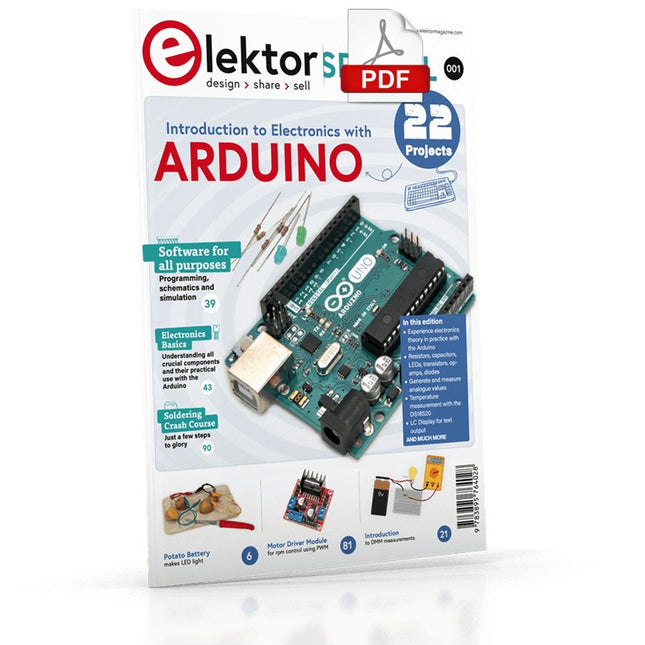
Elektor Digital Elektor Special: Introduction to Electronics with Arduino (PDF)
Although the Arduino isn’t a novelty any longer, there are still many beginners who want to try programming and development with a microcontroller, and to them, it is all new. All beginnings can be difficult, though they should be light and enjoyable. You do not need much or expensive equipment for the examples. The circuits are built on a small breadboard, and, if necessary, connected to an Arduino Uno, which you can program on a Windows PC. You will find clear examples of how to build all circuits, ensuring easy and error-free reproduction. Projects Discussed Current & Voltage – How it all began Arduino Hardware Arduino Programming The Electrical Circuit Measuring with the Multimeter Circuit Diagrams and Breadboards Creating Circuit Diagrams Breadboard Views with Fritzing Online Circuit Simulation Indispensable: Resistors (Part 1) Hands-on with Resistors (Part 2) Variable Resistors Diodes: One-way Street for Current The Transistor Switch Electromagnetism Relays and Motors op-amps: Operational Amplifiers Capacitors The NE555 Timer PWM and Analogue Values with Arduino 7-Segment Temperature Display Introduction to Soldering and LCDs
€ 11,95
Members € 10,76
-
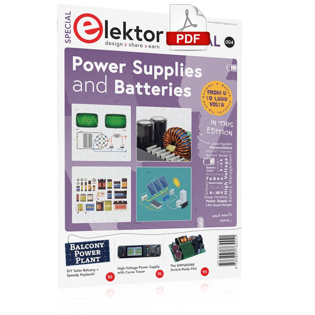
Elektor Digital Elektor Special: Power Supplies and Batteries (PDF)
Whatever the methods or even then financial means you have to make your circuits work, the power supply should rank high if not Number One in your considerations. The design block simply called “power supply” is hugely underrated both in electronics creation and repair. Yet, the “PSU” has enormous diversity and comes in wildly differing guises like AC/DC, generator, battery (rechargeable or not), PV panel, benchtop, linear or switch-mode, to mention but a few. The output ranges are also staggering like nano-amps to kiloamps and the same for voltages.This special covers the features and design aspects of power supplies.ContentsBasics Battery ManagementWhat to be aware of when using (Lithium) batteries. Fixed-Voltage Power Supply using Linear RegulatorsThe best result right after batteries. Light Energy HarvestingA small solar panel is used in an energy harvesting project to manage and charge four AAA cells. Mains Powered Adapter DesignBasic circuits and tips for transformers, rectification, filtering and stabilization. LM317 Soft StartThe high inrush current pulse should be avoided. Controllable RectifiersSome suggestions to keep the power loss in the linear regulator as low as possible. Components Worksheet: The LM117 / LM217 / LM317 Voltage Regulators SupercapsLow voltage but lots of current… or not? Reviews JOY-iT RD6006 Benchtop Power Supply Kit Siglent SDL1020X Programmable DC Electronic Load Projects Balcony Power PlantDIY solar balcony = speedy payback! DIY LiPo Supercharger KitFrom handcrafted to mass market Dual-Anode MOSFET ThyristorFaster and less wasteful than the old SCR Battery JuicerDo not throw away, squeeze! High-Voltage Power Supply with Curve TracerGenerate voltages up to 400 V and trace characteristics curves for valves and transistors High Voltage Supply for RIAAFor RIAA tube preamps and other applications. MicroSupplyA lab power supply for connected devices Phantom Power Supply using Switched CapacitorsVoltage tripler using three ICs The SMPS800RE Switch-Mode Supply for the Elektor Fortissimo-100Reliable, light and affordable Soft Start for PSUBe nice to your power supply – and its load UniLab 20-30 V, 3 A compact switch-mode lab power supply Tips Soft Start for Step-Down Switching Regulators Low Loss Current Limit Powerbank Surprise A Virtual Ground Battery Maintainer Battery Pack Discharger Connecting Voltage Regulators in Parallel
€ 11,95
Members € 10,76
-
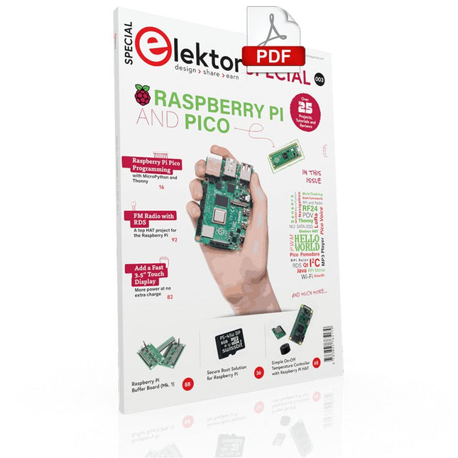
Elektor Digital Elektor Special: Raspberry Pi and Pico (PDF)
Contents Projects PicoVoiceVoice alienation and sound effects with the Raspberry Pi Pico Navigation with Vibration Feedback POV Display Pulse Width Modulation (PWM) with the Raspberry Pi Pico Wi-Fi with the Raspberry Pi Pico 'Hello World' from the Raspberry Pi Pico and RP2040A look at the Raspberry Pi Foundation’s first microcontroller Simple On-Off Temperature Controller with Raspberry Pi HAT Multitasking with the Raspberry PiShowcase: a traffic lights controller The Raspberry Pi Ruler GadgetFun with a time-of-flight sensor Raspberry Pi Buffer Board (Mk. 1)Never blow up the I/O again FM radio with RDSA top HAT project for the Raspberry Pi LoRa with the Raspberry Pi PicoFun with MicroPython! Tutorials Qt for the Raspberry Pi Raspberry Pi Pico Programmingwith MicroPython and Thonny Raspberry Pi Full StackRPi and RF24 at the heart of a sensor network Raspberry Pi Bash Command Cheat Sheet Community Java on the Raspberry PiAn interview with Frank Delporte Reviews Introducing the New Raspberry Pi Pico W, H, and WH Secure Boot Solution for Raspberry PiRetrofit security at a reasonable price Review: SmartPi – Smart Meter Extension for Raspberry Pi Review: The Enviro+ Raspberry Pi HATMeasuring environmental data with Raspberry Pi and the HAT Enviro+ Review: Meet the Raspberry Pi 4All new but still good? Raspberry Pi Gets a Fast 3.5' Touch DisplayMore power at no extra charge Book Launch: Raspberry Pi for Radio Amateurs
€ 11,95
Members € 10,76
-

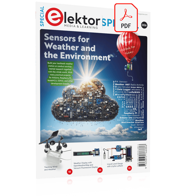
Elektor Special: Sensors for Weather and the Environment
Build your textbook weather station or conduct environmental research together with the whole world. With many practical projects for Arduino, Raspberry Pi, NodeMCU, ESP32, and other development boards. Weather stations have enjoyed great popularity for decades. Every current and even every long discontinued electronics magazine has regularly featured articles on building your own weather station. Over the years, they have become increasingly sophisticated and can now be fully integrated into an automated home — although this often requires loyalty to an (expensive) brand manufacturer across all components. With your own weather and environmental data, you can keep up and measure things that no commercial station can. It’s also fun: expand your knowledge of electronics, current microcontroller development boards and programming languages in a fun and meaningful way. For less than 10 euros you can get started and record your first environmental data — with time and growing interest, you will continue to expand your system. In this Edition Which Microcontroller Fits My Project? The Right Development Environment Tracking Wind and Weather Weather Display with OpenWeatherMap and Vacuum Fluorescent Display Volatile Organic Compounds in the Air We Breathe Working with MQ Sensors: Measuring Carbon Monoxide — Odorless but Toxic CO2 Traffic Light with ThingSpeak IoT Connection An Automatic Plant Watering System Good Indoor Climate: Temperature and Humidity are Important criteria Classy Thermometer with Vintage Tube Technology Nostalgic Weather House for the Whole Family Measuring Air Pressure and Temperature Accurately Sunburn Warning Device DIY Sensor for Sunshine Duration Simple Smartphone Says: Fog or Clear View? Identifying Earthquakes Liquid Level Measurement for Vessels and Reservoirs Water pH Value Measurement Detecting Radioactive Radiation GPS: Sensor Location Service Across the Globe Saving and Timestamping Log Files on SD Cards LoRaWAN, The Things Network, and ThingSpeak Operating a LoRaWAN Gateway for TTN Defying "Wind and Weather" Mega Display with Weather Forecasz
€ 19,95
Members € 17,96
-
Elektor Digital Elektor Special: Sensors for Weather and the Environment (PDF)
Build your textbook weather station or conduct environmental research together with the whole world. With many practical projects for Arduino, Raspberry Pi, NodeMCU, ESP32, and other development boards. Weather stations have enjoyed great popularity for decades. Every current and even every long discontinued electronics magazine has regularly featured articles on building your own weather station. Over the years, they have become increasingly sophisticated and can now be fully integrated into an automated home — although this often requires loyalty to an (expensive) brand manufacturer across all components. With your own weather and environmental data, you can keep up and measure things that no commercial station can. It’s also fun: expand your knowledge of electronics, current microcontroller development boards and programming languages in a fun and meaningful way. For less than 10 euros you can get started and record your first environmental data — with time and growing interest, you will continue to expand your system. In this Edition Which Microcontroller Fits My Project? The Right Development Environment Tracking Wind and Weather Weather Display with OpenWeatherMap and Vacuum Fluorescent Display Volatile Organic Compounds in the Air We Breathe Working with MQ Sensors: Measuring Carbon Monoxide — Odorless but Toxic CO2 Traffic Light with ThingSpeak IoT Connection An Automatic Plant Watering System Good Indoor Climate: Temperature and Humidity are Important criteria Classy Thermometer with Vintage Tube Technology Nostalgic Weather House for the Whole Family Measuring Air Pressure and Temperature Accurately Sunburn Warning Device DIY Sensor for Sunshine Duration Simple Smartphone Says: Fog or Clear View? Identifying Earthquakes Liquid Level Measurement for Vessels and Reservoirs Water pH Value Measurement Detecting Radioactive Radiation GPS: Sensor Location Service Across the Globe Saving and Timestamping Log Files on SD Cards LoRaWAN, The Things Network, and ThingSpeak Operating a LoRaWAN Gateway for TTN Defying "Wind and Weather" Mega Display with Weather Forecasz
€ 14,95
Members € 13,46


